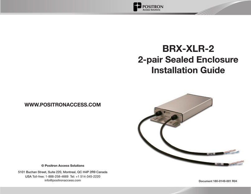
BRX-XLR-2 (2 pairs)
Summary Diagram of Typical Installation
DSLAM BRX-XLR
5-9 kft / 1.5-2.7 km from DSLAM (for 26 AWG / 0.4 mm equivalent gauge copper)
L1
Distance from DSLAM
L2
Distance to CPE
Connecting the BRX-XLR-2
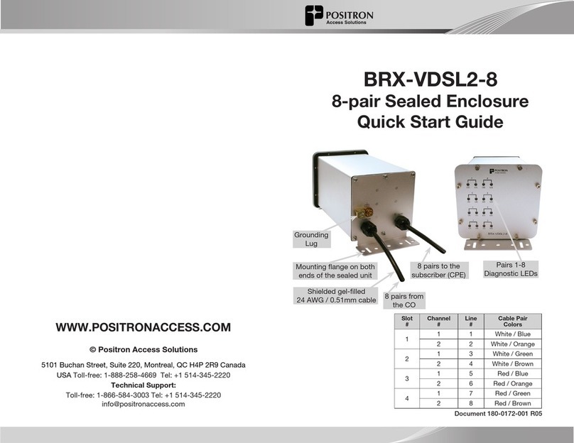
Mounting flange on both
ends of the sealed unit
2 pairs from the CO
2 pairs to the
subscriber (CPE)
Shielded gel-filled
24 AWG/ 0.51mm cable
IMPORTANT NOTE: The BRX-XLR-2 unit is powered from the Sealing Current found on a standard POTS pair.
The BRX-XLR-2 will not work on a dry pair (line with no sealing current). Each pair of the BRX-XLR-2 is
powered independently with each pair requiring the presence of the sealing DC Voltage for proper operation.
Grounding Lug
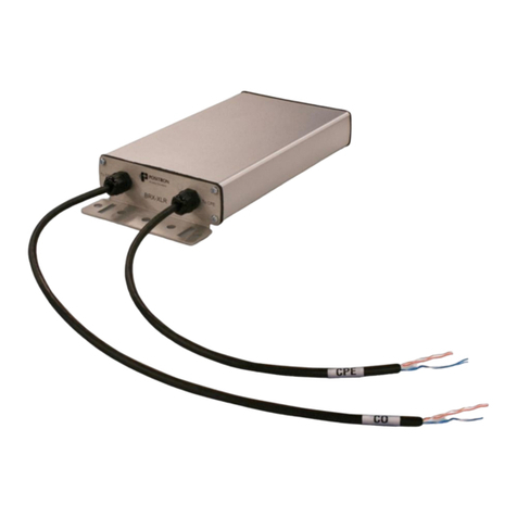
CPE Line 1 Blue / White
CPE Line 2 Orange / White
CO Line 1 Blue / White
CO Line 2 Orange / White
Step 1:
Select the location where the BRX-XLR-2 will be inserted
using the BRX-XLR Calculator
To download the BRX-XLR Calculator, sign up on the Portal
at www.positronaccess.com/Portal.php
You will get a username and password to access the Portal
Step 2:
Connect the grounding lug of the unit to a proper ground
(usually available near a splice point)
Step 3:
Connect one of the CO pairs to a pair from the DSLAM
Step 4:
Connect the corresponding CPE pair to the pair going to
the subscriber home
IMPORTANT: Make sure to match CO pair# to CPE pair#
After step 4, the DSLAM and the CPE will retrain the circuit
and bring up the ADSL2+ / ADSL link with the higher
bandwidth. Note that the performance may be limited (or
capped) by a setting in the DSLAM configuration.
Document 180-0149-001 R05
