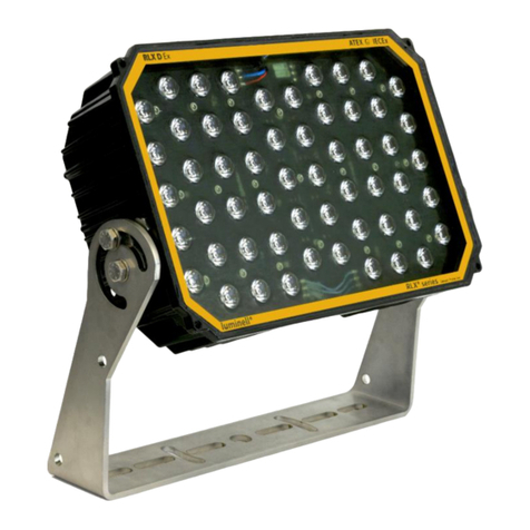
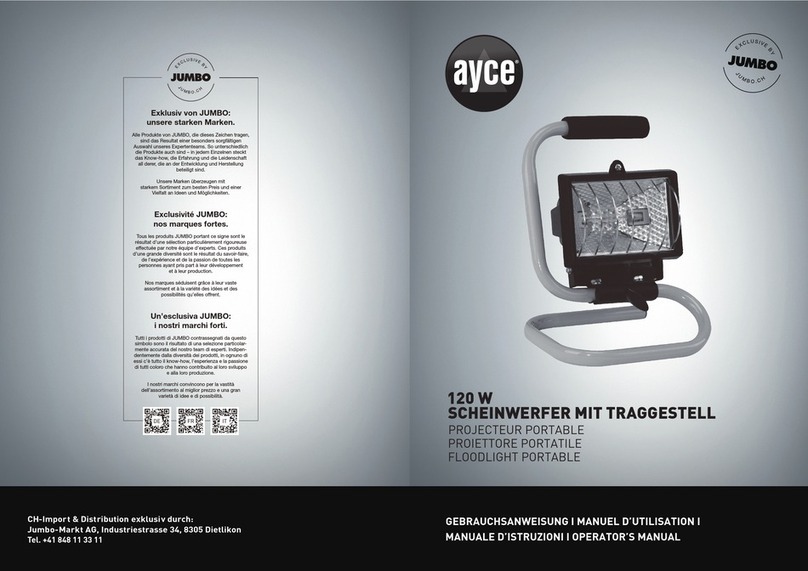
Teryair TSL-50 FLOOD TYPE Instruction Manual

TSL-50AF and TSL-50AB Aluminum and Brass Construction, All variants
Models Descriptions
TSL-50AF Compressed Air Driven Flood Lamp- (Aluminium)
TSL-50BF Compressed Air Driven Flood Lamp- (Brass)
TSL-50AB Compressed Air Driven Bay Lamp- (Aluminium)
TSL-50BB Compressed Air Driven Bay Lamp- (Brass)
TSL-50 FLOOD TYPE TSL-50 BAY TYPE
Read this manual carefully before installing, operating or servicing this equipment. It’s the
responsibility of the employer to ensure this manual is read by the operator. Please preserve this
manual.
is document is issued with Product Serial No
Operation and Maintenance Guide

FF-MM-365-REV - 00
Page 2
Operation and Maintenance Guide Compressed Air Driven Lamp
Table of Contents
3 Introducon
3 Warning&SafetyInstrucons
4 Lubricaon
4 Maintenance
4 Dis-AssemblyandRe-assemblyinstrucons:
6 Technical Data Compressed Air Driven Lamp
7 Exploded View for TSL-50 AF-BF
8 Exploded View Detail-A for TSL-50 AF-BF
9 Exploded View Detail-B for TSL-50 AF-BF
10 Exploded View Detail-C for TSL-50 AF-BF
11 Bill of Materials for TSL-50BF
12 Bill of Materials for TSL-50AF
13 Exploded View for TSL-50 AB-BB
14 Exploded View Detail-A for TSL-50 AF-BF
15 Exploded View Detail-B for TSL-50 AF-BF
16 Exploded View Detail-C for TSL-50 AF-BF
17 Bill of Materials for TSL-50BB
18 Bill of Materials for TSL-50AB
19 Repair Kits
19 Repair Kits for Compressed Air Driven Lamp Flood Type and Bay Type
19 OponalAccessories
20 Dimensional Data
21 WarrantyCercate

FF-MM-365-REV - 00
Page 3
Operation and Maintenance Guide Compressed Air Driven Lamp
Introduction
e Teryair Compressed Air Driven Lamp are
250 Watt Tungsten Halogen compressed air
operated Compressed Air Driven Lamps.
• TSL-50 (Flood Type) has a Reector Head
with Polished reector providing wide
angle or concentrated levels of Food lighting.
• TSL-50 (Bay Models) has a bay light tting
comprising a bell glass and protective
polycarbonate dome to provide all round
general purpose illumination and a hook
provided for suspension of the lamp in the
working area of simple fastening to a tripod.
Quality Assurance Standards to ISO 9001:2015
to apply to manufacture, assembly, nal
inspection and testing of all lamp units.
Warning & Safety Instructions
Warning. Static Electricity
Static sparks can cause explosion resulting
in severe injury or death. Ground the Com-
pressed Air Driven Lamp and the safety lamp
connections like hoses and containers into
which or from the uid is being transferred.
Connect the grounding wire to any bolt on the
Compressed Air Driven Lamp. Check conti-
nuity of electrical path to ground at regular
intervals. Consult local building and electrical
codes for grounding requirements where nee-
ded. Use hoses containing a grounding wire.
Warning: Opening in
Hazardous Atmosphere
Do not open when an explosive atmosphere is
present.
Dirt or moisture from unltered air will
deposit on the inside of the glass disc or ball
glass, reducing light output. Use clean
In a hazardous area shut o air supply and wait
two minutes before dismantling the lamp. e
reector head and ball glass of the lamps are
pressurized enclosures. Do not cover or
obscure light transmitting parts.
Warning: Exhaust Air
In presence of combustible dust in mining or
other application, the exhaust air must be
contained and piped away into a safe zone.
Safety lamp with brass construction models
like TSL-50BB & TSL-50BF are used for such
application.
e hoses used with product shall be
anti-static hoses with surface resistance in
between 10^4 to 10^8 ohms.
Warning: Over-pressure/
Hazardous Pressure
Do not exceed the max supply air pressure of
115 PSI. Make sure all connected hoses and
pipelines are rated to operate safely with the
pressures generated by safety lamp of 115 PSI.
Do not open or handle safety lamp or hoses
while pressurized.
Disconnect air supply line and relieve pressure
from the system by carefully opening discharge
and supply lines.
Caution: Operator
understanding
Please ensure that all operators have read this
manual and have the required understanding
of safe working practices and are equipped with
safety equipment when working on/around the
safety lamp.
Caution: Using genuine teryair
fittings & spares
Use genuine teryair parts to ensure correct
safety lamp operation and maximize life.
Incorrect Fastening of these
Screws can cause
1. e toughened Glass Disc/Bell Glass to
shatter.
2. e Rubber Ring Grooved/bottom Glass
Seal to become damaged.
3. Weakening of the Fastening Screws.

FF-MM-365-REV - 00
Page 4
Operation and Maintenance Guide Compressed Air Driven Lamp
Dis-Assembly and Re-assembly
instructions:
Lubrication
Warning
1. Control of Environmental humidity to min-
imize the generation of the static electricity.
2. Protection from direct airow causing a
charge transfer.
3. Touch with an insulating object to avoid
electrostatic charge hazard.
4. Clean the surface with damp cloth only to
avoid electrostatic charge hazard.
(Refer page no. ----- for exploded view)
Any dust, grit or dirt in the compressed air can
contaminate the grease and bearings causing
severe damage.
Appropriate air line lters must be used in
dusty environments.
a) e Self Aligning Ball Bearings (29) and
grease must be clean to prevent damage. e
magneto type Bearings require a medium
grade none mollifying grease, which should be
applied aer 1000 hours running time. Grease
nipples are not tted. Access to the Bearings
requires removing just the three Fastening
Screws (17) in the Top Cover (27). If the Top
Cover (27) resist removal, then the edge of the
rim should be tapped with a mallet at several
points to free the joint. e Rotor Assembly
(23) can then be lied out of the open Stator
Housing (28). is will require either a pair of
pliers or the aid of Key on Nut for Rotor Sha
(30). (Refer page no. ----- for exploded view)
b) A smear of grease can then be applied to the
caged Self Aligning Ball Bearings (29) on each
end of the Rotor Sha (34) and the races situa-
ted in the Stator Housing (28) and Top Cover
(27) respectively.
c) Before replacing the Rotor Assembly (23)
make sure that no small ferrous objects have
been attracted to the Rotor Disc. Care must be
Maintenance
A regular maintenance programme is highly
recommended for these precision approved
products to enable continued safe use of the-
se lamps in the explosive environments. e
maintenance and repair of Teryair Compressed
Air Driven Lamp should only be undertaken
by trained or qualied electrical tters or
engineers. Lamp should be cleaned and tested
in every three months if in regular use, and
every six months where use is less frequent. As
a guide, reference may be made to the use of
incorrect spare parts and the improper tting
of spare parts will invalidate the manufactu-
rer’s Guarantee. Full details of maintenance
and repair procedures follow. If in doubt
contact the manufacturer.
Before beginning to disassemble lamp, discon-
nect the air hose from lamp and allow inter-
nals of lamp to cool down for 4~5 minutes
before beginning disassemble.
1) Bulb Maintenance and Replacement.
e 24 Volt 250 Watt Tungsten Halogen Bulb
should be handled with care, if it becomes
misted or dirty it should be cleaned with a
so cloth, moistened with mentholated spirit.
1.1) TSL50AF-BF - To gain access to the
Bulb, the Reector Head (26) is unlocked by
releasing Grub screw (26A), which allows it.to
be unscrewed from the Stator Housing (28).
(Refer page no. --TSL50AF-BF Detail C-- for
exploded view)
1.2) TSL50AB-BB -To gain access to the Bulb.
PC Guard (16) for Bell Glass (19) is removed
from the Stator Housing (28) by special Span-
ner.
4. Stripping of the threads in the Reector
Head/Upper Locking Ring.
taken when replacing the Rotor Assembly (23)
to avoid ngers becoming trapped between
the Turbine Wheel (1) and the Stator Housing
as (28) the Magnet is attracted to the Winding
Assembly (22).

FF-MM-365-REV - 00
Page 5
Operation and Maintenance Guide Compressed Air Driven Lamp
Care should be taken to avoid damaging the
replacement bulb (51). when
locating the pins in the spring loaded
contacts of the Bulb holder (21). When
replacing Lower locking ring (25) screw
down on the ‘O’ ring (45) with sucient
torque to seal the pressurized enclosure.
(Refer page no. --TSL50AB-BB Detail
C -- for exploded view)
2.1) Replacing/Cleaning Glass Disc – TSL-
50AF-BF. (Refer page no. --TSL50AF-BF
Detail C-- for exploded view) e Reector
Head(26) of e Teryair Safety Lamp Is A
Pressurized Enclosure. e End Cover (25)
retains the Glass Disc (19) (15mm) to remove.
Unfasten the four socket head screw (17). e
Glass Disc (19) is mounted inside the Rubber
Ring Grooved (44), e Reector (16) sits in
the reector head (26). ese items can be
remove for cleaning/replacement .e Rubber
Ring Grooved (44) in particular should be
inspected for any damage, as this provides a
pressurized seal on both faces of the Reector
Head enclosure. When re-assembling ensure
that the Rubber Ring Grooved (44) is evenly
tted on both faces of the Glass Disc (19).
Place Reector (16) in Reector Head (26)
before the End Cover (25) and seal refastening
of this assembly into the Reector Head(26)
must follow normal good practice in fastening
down a anged joint of the four Screws (17).
2.2) Replacing/Cleaning Bell Glass – TSL-
50AB-BB. (Refer page no. --TSL50AB-BB
Detail C-- for exploded view)e Lower
Locking Ring (25) is unscrewed from the Up-
per Locking Ring (26) using special spanner
and can access Bell Glass (19).ese items
can be remove for cleaning /replacement. e
Bottom Glass Seal (45) in particular should
be inspected for any damage, as this provides
a pressurized seal on both faces of the Upper
Locking Ring (26) enclosure. When re-as-
sembling ensure that the Top Glass Seal (44)
is placed between Bell Glass (19) and Low-
er Locking Ring (25). When re-assembling
ensure also that the Bottom Glass Seal (45) is
evenly tted on faces of the Bell Glass (19) and
Upper Locking Ring (26). Seal Fastening of
this assembly into Stator housing must follow
normal good practice in fastening down.
3) Replacing Bearings. (Refer page no.
--TSL50AF-BF Detail A--/TSL50AB-BB
Detail A for exploded view) Access to the
Bearings requires removing just the three
Fastening Screws (17) in the Top Cover (27).
If the Top Cover (27) resist removal, then the
edge of the rim should be tapped with a mallet
at several points to free the joint. e Rotor
Assembly (23) can then be lied out of the
open Stator Housing (28). Remove Nut for
Rotor Sha (30) on the Rotor Assembly (23),
Washer for nut (40), Self Aligning Ball Bearing
(29), Turbine Wheel (1), Rotor Assembly (23)
and Spacer for Rotor Sha (37) and nally Sec-
ond Self Aligning Ball Bearing (29), from the
Rotor Sha (34). ese parts should be cleaned
and replaced in reverse order together with
new Self Aligning Ball bearings (29). Under-
neath each of the outer races of the Bearings
is tted a Waved Spring Washer (8). ese
ensure the correct loading of the bearings. It
is important to check that these Waved Spring
Washers are in good condition before tting
the new outer Bearing races.
4) Air Regulator Assembly. (Refer page no.
--TSL50AF-BF Detail B--/TSL50AB-BB
Detail B for exploded view)All the Air Reg-
ulator parts are secured by Male Connector
(3) and should not be disturbed unless the
regulator cases to function correctly . e
Male connector (3) serves also to align the
Air Regulating Plate (31) the Piston Spacer
(24). Now remove the piston assembly. e
piston (35) tted with rolling Diaphragm
(43) by Screw for Piston (46). ese parts are
withdrawn from the front of the piston cham-
ber and should be cleaned and examined for
wear and damage and replaced as necessary.

FF-MM-365-REV - 00
Page 6
Operation and Maintenance Guide Compressed Air Driven Lamp
In particular the Diaphragm (43) should be
checked for damage. Before re-assembly of the
piston assembly, Take out the Governor spring
(20) and locate it in the Guide Bush (38). Now
insert the assembly with spring in the stator
housing (28). Tighten the Male connector (3)
in reverse manner.
5) Replacing Bulb holder Assembly.
Bulb holder (21) has been tted to all Lamps
and incorporates a proprietary ceramic bipin
holder and the whole unit is sealed in
production, but is otherwise a direct substitute
for the old one. To gain access to the Bulb
holder in -TSL50AF-BF-To gain access to the
Bulb, the Reector Head (26) is unlocked by
releasing Grub screw (26A), which allows it to
be unscrewed from the Stator Housing (28).
e Bulb holder (21) is positioned inside the
Reector Head (26) fastened by the two Nuts
(13) on Stator terminal, which pass through
the wall of the Stator Housing (28).
TSL50AB-BB- PC Guard (16) for Bell Glass
(19) is removed from the Stator Housing
(28) by special Spanner. e Bulb holder
(21) is positioned inside the Reector Head
(26) fastened by the two Nuts (13) on Stator
terminal, which pass through the wall of the
Stator Housing (28). ese Screws (15) are
insulated and sealed by insulating Bushes
(42), and carry the power from the Wind-
ing Assembly (22).If removed, it is essential
to ensure that the Insulating Bushes are in
good condition as well as providing electrical
insulation, because they also provide a
pressure seal between the Reector Head
and the Stator Housing.
Technical Data Compressed Air Driven Lamp
Product Reference TSL-50 BAY TYPE TSL-50 FLOOD TYPE
Product Description “Compressed Air Driven Bay Lamp ” “Compressed Air Driven Flood Lamp”
Enclosure Aluminium Brass Aluminium Brass
Lens Ball Glass/Polycarbonate Dome Toughened Glass(15mm)
Beam Type All-around 360 Illumination Flood (Matt Reector) (as Standards) or
Spot (Polished Reector) (to Order)
Light
Source
Part No TSL-50AB TSL-50BB TSL-50AF TSL-50BF
Type Tungsten halogen lament bulb
Volts 24 V
Watts 250 W
Output 6000Lm
Power
Source
Type Compressed air-driven turbo-alternator
Air Pressure 60~115 psi/ 4.0~8.0 bar
Consumption 26.5 cfm/ 0.75m³/min
Ingress Protection Once pressurized, may be used under water
Weight 5.7 Kg 10 Kg 7.0 Kg 12.2 Kg
Special Certication Condition A clean dry air supply must be used. Supply hose must be anti-static
• All information has been gathered under laboratory conditions, the user must regard the values given as approximate.
• Changes may be made to the above specication without notication, details are available on request.

FF-MM-365-REV - 00
Page 7
Operation and Maintenance Guide Compressed Air Driven Lamp
Exploded View for TSL-50 AF-BF

FF-MM-365-REV - 00
Page 8
Operation and Maintenance Guide Compressed Air Driven Lamp
Exploded View Detail-A for TSL-50 AF-BF

FF-MM-365-REV - 00
Page 9
Operation and Maintenance Guide Compressed Air Driven Lamp
Exploded View Detail-B for TSL-50 AF-BF

FF-MM-365-REV - 00
Page 10
Operation and Maintenance Guide Compressed Air Driven Lamp
Exploded View Detail-C for TSL-50 AF-BF

FF-MM-365-REV - 00
Page 11
Operation and Maintenance Guide Compressed Air Driven Lamp
Bill of Materials for TSL-50BF
Illu.
No.
Part
No. Description TSL-50BF
1 469 04 01 TURBINE WHEEL ASSLY. 1
2 469 25 01 NIPPLE 1
3 469 25 02 MALE CONNECTOR 1
4 469 25 03 OVER THROW NUT 1
5 469 90 01 PLAIN WASHER 1
6 469 90 02 SAFETY HOOK 1
7 469 90 03 EYE BOLT 1
8 469 90 04 WAVE WASHER 2
9 469 21 14 HANDLE 1
10 469 90 05 WING NUT 2
11 469 90 06 ALLEN BOLT 6
12 469 90 07 PHILIPS PAN 3
13 469 90 08 HEX NUT 2
14 469 90 09B PLAIN WASHER 2
15 469 90 10 CHEESE HEAD SCREW 2
16 469 81 01 REFLECTOR 1
17 469 90 11 ALLEN BOLT 7
18 469 90 12 HEX NYLOC NUT 1
19 469 59 01 GLASS DISC 1
20 469 51 01 GOVERNOR SPRING 1
21 469 98 01 BULB HOLDER 1
22 469 98 02 WINDING ASSEMBLY 1
23 469 21 09 ROTOR ASSLY. 1
24 469 21 05 SPACER FOR PISTON 1
25 469 04 04 END COVER-BR 1
26 469 04 05 REFLECTOR HEAD-BR 1
26A 469 90 13 GRUB SCREW 1
27 469 04 03 TOP COVER-BR 1
Illu.
No.
Part
No. Description TSL-50BF
28 469 04 06 STATOR HOUSING-BR 1
29 469 50 01 SELF ALIGNING BALL BRG 2
30 469 21 01 NUT FOR ROTOR SHAFT 1
31 469 21 10 AIR REGULATING PLATE 1
32 469 21 16 LOCK SCREW 1
33 469 21 15 HANDLE BOLT 2
34 469 21 04 ROTOR SHAFT 1
35 469 21 13 PISTON 1
36 469 21 08 REGULATING SCREW 1
37 469 21 03 SPACER FOR ROTOR SHAFT 1
38 469 21 12 GUIDE BUSH 1
39 469 21 07 LOCK NUT REGULATING SCREW 1
40 469 21 02 WASHER FOR NUT 1
41 469 40 01 O' RING ID5.5 X 1.7MM- NBR 3
42 469 08 01 INSULATING BUSH 2
43 469 40 02 DIAPHRAGM 1
44 469 40 07 RUBBER RING GROOVED 1
45 469 40 03 O' RING ID101 X 3MM-NBR 1
46 469 21 11 SCREW FOR PISTON 1
47 469 21 06 COLLOR FOR LOCK SCREW 1
48 469 04 02 AIR INLET PLATE 3
49 469 50 02 MUFFLER 3/8" BSPP 1
50 469 90 14 LOCK WASHER 2
51 466 91 01 Ex-HALOGEN BULB 1

FF-MM-365-REV - 00
Page 12
Operation and Maintenance Guide Compressed Air Driven Lamp
Bill of Materials for TSL-50AF
Illu.
No.
Part
No. Description TSL-50BF
1 469 04 01 TURBINE WHEEL ASSLY. 1
2 469 25 01 NIPPLE 1
3 469 25 02 MALE CONNECTOR 1
4 469 25 03 OVER THROW NUT 1
5 469 90 01 PLAIN WASHER 1
6 469 90 02 SAFETY HOOK 1
7 469 90 03 EYE BOLT 1
8 469 90 04 WAVE WASHER 2
9 469 21 14 HANDLE 1
10 469 90 05 WING NUT 2
11 469 90 06 ALLEN BOLT 6
12 469 90 07 PHILIPS PAN 3
13 469 90 08 HEX NUT 2
14 469 90 09B PLAIN WASHER 2
15 469 90 10 CHEESE HEAD SCREW 2
16 469 81 01 REFLECTOR 1
17 469 90 11 ALLEN BOLT 7
18 469 90 12 HEX NYLOC NUT 1
19 469 59 01 GLASS DISC 1
20 469 51 01 GOVERNOR SPRING 1
21 469 98 01 BULB HOLDER 1
22 469 98 02 WINDING ASSEMBLY 1
23 469 21 09 ROTOR ASSLY. 1
24 469 21 05 SPACER FOR PISTON 1
25 469 10 03 END COVER-AL 1
26 469 10 04 REFLECTOR HEAD-AL 1
26A 469 90 13 GRUB SCREW 1
Illu.
No.
Part
No. Description TSL-50BF
27 46910 01 TOP COVER-AL 1
28 469 10 02 STATOR HOUSING-AL 1
29 469 50 01 SELF ALIGNING BALL BRG. 2
30 469 21 01 NUT FOR ROTOR SHAFT 1
31 469 21 10 AIR REGULATING PLATE 1
32 469 21 16 LOCK SCREW 1
33 469 21 15 HANDLE BOLT 2
34 469 21 04 ROTOR SHAFT 1
35 469 21 13 PISTON 1
36 469 21 08 REGULATING SCREW 1
37 469 21 03 SPACER FOR ROTOR SHAFT 1
38 469 21 12 GUIDE BUSH 1
39 469 21 07 LOCK NUT REGULATING SCREW 1
40 469 21 02 WASHER FOR NUT 1
41 469 40 01 O' RING ID5.5 X 1.7MM- NBR 3
42 469 08 01 INSULATING BUSH 2
43 469 40 02 DIAPHRAGM 1
44 469 40 07 RUBBER RING GROOVED 1
45 469 40 03 O' RING ID101 X 3MM-NBR 1
46 469 21 11 SCREW FOR PISTON 1
47 469 21 06 COLLOR FOR LOCK SCREW 1
48 469 04 02 AIR INLET PLATE 3
49 469 50 02 MUFFLER 3/8" BSPP 1
50 469 90 14 LOCK WASHER 2
51 466 91 01 Ex-HALOGEN BULB 1

FF-MM-365-REV - 00
Page 13
Operation and Maintenance Guide Compressed Air Driven Lamp
Exploded View for TSL-50 AB-BB

FF-MM-365-REV - 00
Page 14
Operation and Maintenance Guide Compressed Air Driven Lamp
Exploded View Detail-A for TSL-50 AF-BF

FF-MM-365-REV - 00
Page 15
Operation and Maintenance Guide Compressed Air Driven Lamp
Exploded View Detail-B for TSL-50 AF-BF

FF-MM-365-REV - 00
Page 16
Operation and Maintenance Guide Compressed Air Driven Lamp
Exploded View Detail-C for TSL-50 AF-BF

FF-MM-365-REV - 00
Page 17
Operation and Maintenance Guide Compressed Air Driven Lamp
Bill of Materials for TSL-50BB
Illu.
No.
Part
No. Description TSL-50BF
1 469 04 01 TURBINE WHEEL ASSLY. 1
2 469 25 01 NIPPLE 1
3 469 25 02 MALE CONNECTOR 1
4 469 25 03 OVER THROW NUT 1
5 469 90 01 PLAIN WASHER 1
6 469 90 02 SAFETY HOOK 1
7 469 90 03 EYE BOLT 1
8 469 90 04 WAVE WASHER 2
9 469 21 14 HANDLE 1
10 469 90 05 WING NUT 2
11 469 90 06 ALLEN BOLT 6
12 469 90 07 PHILIPS PAN 3
13 469 90 08 HEX NUT 2
14 469 90 09B PLAIN WASHER 2
15 469 90 10 CHEESE HEAD SCREW 2
16 469 08 02 PC GAURD 1
17 469 90 11 ALLEN BOLT 3
18 469 90 12 HEX NYLOC NUT 1
19 469 65 01 BELL GLASS 1
20 469 51 01 GOVERNOR SPRING 1
21 469 98 01 BULB HOLDER 1
22 469 98 02 WINDING ASSEMBLY 1
23 469 21 09 ROTOR ASSLY. 1
24 469 21 05 SPACER FOR PISTON 1
25 469 15 02 LOWER LOCKING RING-BR 1
26 469 15 01 UPPER LOCKING RING-BR 1
27 469 04 03 TOP COVER-BR 1
27 469 04 03 TOP COVER-BR 1
Illu.
No.
Part
No. Description TSL-50BF
28 469 04 06 STATOR HOUSING-BR 1
29 469 50 01 SELF ALIGNING BALL BRG. 2
30 469 21 01 NUT FOR ROTOR SHAFT 1
31 469 21 10 AIR REGULATING PLATE 1
32 469 21 16 LOCK SCREW 1
33 469 21 15 HANDLE BOLT 2
34 469 21 04 ROTOR SHAFT 1
35 469 21 13 PISTON 1
36 469 21 08 REGULATING SCREW 1
37 469 21 03 SPACER FOR ROTOR SHAFT 1
38 469 21 12 GUIDE BUSH 1
39 469 21 07 LOCK NUT REGULATING SCREW 1
40 469 21 02 WASHER FOR NUT 1
41 469 40 01 O' RING ID5.5 X 1.7MM- NBR 3
42 469 08 01 INSULATING BUSH 2
43 469 40 02 DIAPHRAGM 1
44 469 40 05 TOP GLASS SEAL 1
45 469 40 06 BOTTOM GLASS SEAL 1
46 469 21 11 SCREW FOR PISTON 1
47 469 21 06 COLLOR FOR LOCK SCREW 1
48 469 04 02 AIR INLET PLATE 3
49 469 50 02 MUFFLER 3/8" BSPP 1
50 469 90 14 LOCK WASHER 2
51 466 91 01 Ex-HALOGEN BULB 1
52 469 31 02 SPANNER FOR LOWER LOCKING
RING 1

FF-MM-365-REV - 00
Page 18
Operation and Maintenance Guide Compressed Air Driven Lamp
Bill of Materials for TSL-50AB
Illu.
No.
Part
No. Description TSL-50BF
1 469 04 01 TURBINE WHEEL ASSLY. 1
2 469 25 01 NIPPLE 1
3 469 25 02 MALE CONNECTOR 1
4 469 25 03 OVER THROW NUT 1
5 469 90 01 PLAIN WASHER 1
6 469 90 02 SAFETY HOOK 1
7 469 90 03 EYE BOLT 1
8 469 90 04 WAVE WASHER 2
9 469 21 14 HANDLE 1
10 469 90 05 WING NUT 2
11 469 90 06 ALLEN BOLT 6
12 469 90 07 PHILIPS PAN 3
13 469 90 08 HEX NUT 2
14 469 90 09B PLAIN WASHER 2
15 469 90 10 CHEESE HEAD SCREW 2
16 469 08 02 PC GAURD 1
17 469 90 11 ALLEN BOLT 3
18 469 90 12 HEX NYLOC NUT 1
19 469 65 01 BELL GLASS 1
20 469 51 01 GOVERNOR SPRING 1
21 469 98 01 BULB HOLDER 1
22 469 98 02 WINDING ASSEMBLY 1
23 469 21 09 ROTOR ASSLY. 1
24 469 21 05 SPACER FOR PISTON 1
25 469 10 06 LOWER LOCKING RING-AL 1
26 469 10 05 UPPER LOCKING RING -AL 1
27 46910 01 TOP COVER-AL 1
27 469 04 03 TOP COVER-BR 1
Illu.
No.
Part
No. Description TSL-50BF
28 469 10 02 STATOR HOUSING-AL 1
29 469 50 01 SELF ALIGNING BALL BRG. 2
30 469 21 01 NUT FOR ROTOR SHAFT 1
31 469 21 10 AIR REGULATING PLATE 1
32 469 21 16 LOCK SCREW 1
33 469 21 15 HANDLE BOLT 2
34 469 21 04 ROTOR SHAFT 1
35 469 21 13 PISTON 1
36 469 21 08 REGULATING SCREW 1
37 469 21 03 SPACER FOR ROTOR SHAFT 1
38 469 21 12 GUIDE BUSH 1
39 469 21 07 LOCK NUT REGULATING SCREW 1
40 469 21 02 WASHER FOR NUT 1
41 469 40 01 O' RING ID5.5 X 1.7MM- NBR 3
42 469 08 01 INSULATING BUSH 2
43 469 40 02 DIAPHRAGM 1
44 469 40 05 TOP GLASS SEAL 1
45 469 40 06 BOTTOM GLASS SEAL 1
46 469 21 11 SCREW FOR PISTON 1
47 469 21 06 COLLOR FOR LOCK SCREW 1
48 469 04 02 AIR INLET PLATE 3
49 469 50 02 MUFFLER 3/8" BSPP 1
50 469 90 14 LOCK WASHER 2
51 466 91 01 Ex-HALOGEN BULB 1
52 469 31 02 SPANNER FOR LOWER LOCKING
RING 1

FF-MM-365-REV - 00
Page 19
Operation and Maintenance Guide Compressed Air Driven Lamp
Repair Kits
Illu. No. Part No. Description
Flood 469 97 01
Bay 469 97 02
8 469 90 04 WAVE WASHER 2 2
29 469 50 01 SELF ALIGNING BALL BRG. 2 2
35 469 21 13 PISTON 1 1
38 469 21 12 GUIDE BUSH 1 1
43 469 40 02 DIAPHRAGM 1 1
44 469 40 07 RUBBER RING GROOVED 1
44 469 40 05 TOP GLASS SEAL 1
45 469 40 03 O' RING ID101 X 3MM-NBR 1
45 469 40 06 BOTTOM GLASS SEAL 1
46 469 21 11 SCREW FOR PISTON 1 1
51 466 91 01 Ex-HALOGEN BULB 1 1
Repair KIT Ordering No Suitable for
469 97 01 Flood Type
469 97 02 Bay Type
Repair Kits for Compressed Air Driven Lamp Flood Type and Bay
Type
Optional Accessories
•
Tripod
• Ordering Code - 4669701

FF-MM-365-REV - 00
Page 20
Operation and Maintenance Guide Compressed Air Driven Lamp
Dimensional Data
TSL-50AF-BF
TSL-50AB-BB
This manual suits for next models
5
Table of contents
