TESTING 1.0334 User manual

TESTING Bluhm & Feuerherdt GmbH
Production and distribution of
construction-material testing devices
Motzener Str. 26b
DE - 12277 Berlin, Germany
Tel. +49 (0) 30 710 964 5-0
Fax +49 (0) 30 710 964 5-98
www.testing.de
Operating Manual
Air Entrainment Meter
0.5 litre, 0.75 litre, 1 litre, 5 litre, 7 litre and 8 litre
Model: TESTING, with hand pump

Air Entrainment Meters
0.5 litre; model: TESTING 1.0334 0,75 litre; model: TESTING 1.0337
1 litre; model: TESTING 1.0335 5 litre; model: TESTING 2.0332
7 litre; model: TESTING 2.0337 8 litre; model: TESTING 2.0334
Page 2 of 42 pages
Importance of this Operating Manual:
It is expected that users and operators read and understand this entire Operating Manual
before putting the system into operation.
Contents Page no.:
1. Basic instructions...................................................................................................3
1.1 Purpose for which this system was designed......................................................3
1.2 Purposes for which this system may NOT be used.............................................5
1.3 Safety instructions...............................................................................................5
1.3.1 Obligations of the User.....................................................................................5
1.3.2 Safety elements ...............................................................................................5
1.3.3 Safety information for working with fresh concrete...........................................5
1.3.4 Weights of the air entrainments meters............................................................6
1.4 Acceptance of the product and transport.............................................................6
1.4.1 Acceptance of the product................................................................................6
1.4.2 Transport..........................................................................................................7
1.5 Items delivered with the air entrainment meters:.................................................8
1.6 Technical data...................................................................................................10
1.6.1 Operation of the system.................................................................................10
1.6.2 Basic elements and characteristics of the air entrainment meters .................11
2. The test procedure................................................................................................14
3. Cleaning and maintenance...................................................................................17
4. Checking and calibrating the air entrainment ....................................................18
4.1 Determining the initial pressure.........................................................................18
4.2 Results of testing for the initial pressure............................................................19
4.3 Calibration.........................................................................................................20
4.3.1 Determination of the volume of the test pot:...................................................20
4.3.2 Continuation of the calibration........................................................................21
5. Troubleshooting....................................................................................................24
6. After-sales service and spare parts.....................................................................25
6.1 Date of issue of this Operating Manual..............................................................25
6.2 Copyright...........................................................................................................25
6.3 Contact for help and spare parts .......................................................................26
6.4 Disposal and recycling.......................................................................................26
6.5 List of spare parts for the 0.5-litre......................................................................27
6.6 List of spare parts for the 0.75-litre....................................................................29
6.7 List of spare parts for the 1-litre.........................................................................31
6.8 List of spare parts for the 5-litre.........................................................................33
6.9 List of spare parts for the 7-litre.........................................................................35
6.10 List of spare parts for the 8-litre......................................................................37
7. Calibration instructions........................................................................................39
8. Possible operator mistakes for TESTING air-entrainment meters ...................41
8.1 Pressure drop as a result of screwing down the transport lock .........................41
8.2 Mistakes in operation during determination of air-void content..........................41

Air Entrainment Meters
0.5 litre; model: TESTING 1.0334 0,75 litre; model: TESTING 1.0337
1 litre; model: TESTING 1.0335 5 litre; model: TESTING 2.0332
7 litre; model: TESTING 2.0337 8 litre; model: TESTING 2.0334
Page 3 of 42 pages
Attachments:
1 Sheet: EG Declaration of Conformity
This Operating Manual contains safety instructions that must be followed to prevent
danger in the form of death, injury, damage to equipment, and unprofessional service.
These instructions are classified according to the following icons:
Caution
This warning calls attention to danger that can lead to damage to
equipment or other objects.
Danger
This warning indicates danger that can lead to severe injury or death.
Note
This warning gives practical instructions on actions to be taken.
1. Basic instructions
1.1 Purpose for which this system was designed
This Operating Manual explains the operation of five air entrainment meters, all with
identical functions. If a list of different technical data or parameters is given, then they shall
apply to the three models as follows:
1. 0.5 litre; TESTING article no. 1.0334
2. 0.75 litre; TESTING article no. 1.0337
3. 1 litre; TESTING article no. 1.0335
4. 5 litre; TESTING article no. 2.0332
5. 7 litre; TESTING article no. 2.0337
6. 8 litre; TESTING article no. 2.0334

Air Entrainment Meters
0.5 litre; model: TESTING 1.0334 0,75 litre; model: TESTING 1.0337
1 litre; model: TESTING 1.0335 5 litre; model: TESTING 2.0332
7 litre; model: TESTING 2.0337 8 litre; model: TESTING 2.0334
Page 4 of 42 pages
This Operating Manual contains the information required for operation of the products
described here, for the purpose for which they have been designed. This Operating
Manual is intended to be used only by technically qualified staff.
“Technically qualified staff” is defined as those persons who – as a result of their training;
their experience; the instructions which they have received; as well as their knowledge of
the relevant standards, regulations, accident-prevention regulations, and conditions under
which the product will be operated in the company –have been authorized by the person
responsible for the safety of the company facilities and staff to carry out the activities and
actions required for operation of the equipment described below, and who can recognize
and prevent any possible dangers arising from such operation.
The User must by all means observe the requirements and limit values, as well as all
safety instructions, given in this Operating Manual. Any use of this device not in conformity
with these stipulations shall be considered tobe in violation of the usefor which this system
was intended. If this device must be operated under special conditions, or with special
modes of operation, then this is authorized only after consultation with the manufacturer,
and after obtaining his prior and express approval.
•The 0.5-litre air entrainment meter has been manufactured in accordance with the
standard DIN EN 459 T.2.
•The 0.75-litre air entrainment meter has been manufactured in accordance with the
standard DIN EN 459 T.2.
•The 1-litre air entrainment meter has been manufactured in accordance with the
standard DIN EN 459 T.2
•The 5-litre air entrainment meter has been manufactured in accordance with the
standard DIN EN 12350-T.7.
•The 7-litre air entrainment meter has been manufactured in accordance with the
standards DIN EN 12350-T.7, ASTM C 231
•The 8-litre air entrainment meter has been manufactured in accordance with the
standards DIN EN 12350-T.7, ASTM C 231, and GOST 10181.
To improve the workability of mortar and concrete mixtures, and to enhance the durability
of mortar and concrete under conditions of frost and thawing weather conditions,
admixtures are mixed in with the concrete during its preparation that promote the
development of air voids (air entrainment). If properly applied, this technique can achieve
an optimum in the feasible technological enhancement of the concrete mixture in the total
volume. Frequent tests are essential in order to maintain at a constant level the air
entrainment level that has been determined as optimal for a particular kind of concrete.
The air entrainment meters being described here monitor the effects of air-entraining
admixtures.
These air entrainment meters measure the air void content in fresh concrete and directly
show this content on a pressure gauge in percent.

Air Entrainment Meters
0.5 litre; model: TESTING 1.0334 0,75 litre; model: TESTING 1.0337
1 litre; model: TESTING 1.0335 5 litre; model: TESTING 2.0332
7 litre; model: TESTING 2.0337 8 litre; model: TESTING 2.0334
Page 5 of 42 pages
1.2 Purposes for which this system may NOT be used
Using the air entrainment meters in a manner not in accordance with the pertinent
and valid standards.
1.3 Safety instructions
1.3.1 Obligations of the User
The person operating these systems must take care that he or she does not endanger the
health and safety of himself/herself or of any other persons. No person may operate this
system without supervision unless he or she has received sufficient instruction in its
operation.
If these air entrainment meters are damaged, or have any malfunctions that can impair
their operational safety, they must be immediately placed out of operation and the
malfunctions must be corrected. These systems may not be further operated until all such
malfunctions or shortcomings have been eliminated.
These air entrainment meters may be used only:
•For the purpose for which they were intended
•In a technical condition in which they can be perfectly safely operated.
1.3.2 Safety elements
Securing the hand pump for transport
To prevent damage to the hand pump, screw it down into the top part of the pump before
transport. Screw the ball head (the knob) down tight into the top of the pump.
Locking spring on the quick-release latches
The quick-release latches are provided with a locking spring to prevent them from
accidentally opening during conduct of testing.
1.3.3 Safety information for working with fresh concrete

Air Entrainment Meters
0.5 litre; model: TESTING 1.0334 0,75 litre; model: TESTING 1.0337
1 litre; model: TESTING 1.0335 5 litre; model: TESTING 2.0332
7 litre; model: TESTING 2.0337 8 litre; model: TESTING 2.0334
Page 6 of 42 pages
Caution
The mixing of cement with water causes the release of alkaline
substances. In working with concrete, it is essential to take all
necessary precautions to prevent dry cement from entering the eyes,
mouth, or nose. Use protective clothing to prevent skin contact with
wet cement or concrete. If cement or concrete enters the eyes,
immediately and carefully wash out the eyes with clean water. Seek
medical help without delay. If moist concrete comes into contact with
the skin, wash it off immediately.
1.3.4 Weights of the air entrainments meters
When lifting and transporting, make sure to consider the following weights of the meters:
Meter
Weight when empty
Weight when filled with
mortar:
0.5-litre air entrainment meter
approx. 3.8 kg
approx. 4.8 kg
0.75-litre air entrainment meter
approx. 3.9 kg
approx. 5.3 kg
1-litre air entrainment meter
approx. 4.0 kg
approx. 6.0 kg
Weight when filled with
concrete:
7-litre air entrainment meter
approx. 9,1 kg
approx. 24,6 kg
5-litre air entrainment meter
approx. 8.7 kg
approx. 20.2 kg
8-litre air entrainment meter
approx. 9.2 kg
approx. 28.2 kg
When using and transporting the device, please observe the legal regulations applicable
to you.
1.4 Acceptance of the product and transport
1.4.1 Acceptance of the product
When accepting delivery of the product, first inspect it for its outer, visible condition. If this
inspection is satisfactory, the machine may be accepted from the freight forwarder
(package service, courier, or other forwarding business).
If there are no shortcomings, and if there are no transport damages, then use the bill of
delivery to make sure that the consignment is complete, and that all parts have been
delivered.
Air Entrainment Meters
0.5 litre; model: TESTING 1.0334 0,75 litre; model: TESTING 1.0337
1 litre; model: TESTING 1.0335 5 litre; model: TESTING 2.0332
7 litre; model: TESTING 2.0337 8 litre; model: TESTING 2.0334
Page 7 of 42 pages
If you assume or suspect transport damage, or if transport damage becomes apparent
only after you have accepted the delivery, immediately make an exact report of the
conditions and any damage as they exist. Send us this report immediately by fax or e-mail.
Important: Absolutely do not make any changes to the delivered goods.
After we have studied your report, we can make a decision whether we can correct the
difficulties by one of the following options:
•Deliver spare parts to you, or
•Send a specialized fitter/installer to your plant, or
•Ask that you return the system to us for repair.
1.4.2 Transport
This system will be delivered in the specific cardboard boxes. In order to prevent transport
damage, the remaining hollow spaces in the interior of the boxes will be filled with bulk
material.
After the system has been unpacked, it can be moved by hand to the place where it will
be in use by using the handles provided.
The air entrainment meter must be stored and used in a vertical position. When
transporting the meters, make sure not to subject the unit to knocks, bumps, vibrations, or
impacts in order not to damage the sensitive pressure gauge.
Note
When transporting an air entrainment meter, be sure to screw in
the hand pump before transport.
Net weight of these air entrainment meters:
Article numbers:
Model
Empty weight
1.0334
0.5 litre TESTING
3.8 kg
1.0337
0.75 litre TESTING
3.9 kg
1.0335
1 litre TESTING
4.0 kg
2.0332
5 litre TESTING
8.7 kg
2.0337
7 litre TESTING
9,1 kg
2.0334
8 litre TESTING
9.2 kg

Air Entrainment Meters
0.5 litre; model: TESTING 1.0334 0,75 litre; model: TESTING 1.0337
1 litre; model: TESTING 1.0335 5 litre; model: TESTING 2.0332
7 litre; model: TESTING 2.0337 8 litre; model: TESTING 2.0334
Page 8 of 42 pages
1.5 Items delivered with the air entrainment meters:
Description:
Article
number for
the
model
0.5 litre
TESTING
Article
number for
the
model
0.75 litre
TESTING
Article
number for
the
model
1 litre
TESTING
Article
number for
the
model
5 litre
TESTING
Article
number for
the
model
7 litre
TESTING
Article
number for
The
model
8 litre
TESTING
Air
entrainment
meter
1.0334
1.0337
1.0335
2.0332
2.0337
2.0334
Calibration
kit
1.0335K
1.0335K
1.0335K
2.0334K
2.0334K
2.0334K
Operating
manual
No number
No number
No number
No number
No number
No number

Air Entrainment Meters
0.5 litre; model: TESTING 1.0334 0,75 litre; model: TESTING 1.0337
1 litre; model: TESTING 1.0335 5 litre; model: TESTING 2.0332
7 litre; model: TESTING 2.0337 8 litre; model: TESTING 2.0334
Page 9 of 42 pages
Available at an additional price:
Description
0.5 litre
TESTING
0.75 litre
TESTING
1 litre
TESTING
5 litre
TESTING
7 litre
TESTING
8 litre
TESTING
Attachment
ring
for filling
the meter
1.0335.01
1.0335.01
1.0335.01
2.0333.10
2.0337.10
2.0333.10
Transport
container for
construction
sites
1.0335.02
1.0335.02
1.0335.02
2.0333.25
2.0333.25
2.0333.25
Straightedge
for striking
off,
400 mm
2.0237.04
Aluminium
poking rod
2.0237.03
Rubber
hammer
400 g
8.0204
Rubber
hammer
800 g
8.0204-800
Aluminium
hand
shovel 310
mm
8.1203
Squeeze
bottle 500
ml
8.0162
Squeeze
bottle 1000
ml
8.0163
Calibration
record
KAL
Upon request, we can provide you with a calibration record for your air entrainment
meter. You can use this record as evidence for test-equipment monitoring as part of your
quality management programme.
Additional optional items for compaction, available at extra price:
Internal vibrator with minimum frequency of 120 Hz
Vibrating table with minimum frequency of 40 Hz

Air Entrainment Meters
0.5 litre; model: TESTING 1.0334 0,75 litre; model: TESTING 1.0337
1 litre; model: TESTING 1.0335 5 litre; model: TESTING 2.0332
7 litre; model: TESTING 2.0337 8 litre; model: TESTING 2.0334
Page 10 of 42 pages
1.6 Technical data
1.6.1 Operation of the system
These air entrainment meters operate on the principle of Boyle-Mariott’s law. The system
measures the air content of the fresh mortar or fresh concrete in accordance with a
pressure-equalization process. These air entrainment meters have a pressure chamber in
which a specified air pressure is produced by a hand pump. When an overflow valve is
opened, pressure equalization is established with respect to the test pot, which is filled
with the fresh mortar or fresh concrete. The pressure drop is a measure of the air content
in the material.
Basic instructions for use:
Please observe the following instructions for use of the hand pump:
Position of the pump piston, depending on the function required:
Caution
Loose (i.e., not screwed
down)
The piston rod must always
be in this position for
conduct of testing.
Screwed down tight
For transport, the piston
rod must be screwed down
as shown here.

Air Entrainment Meters
0.5 litre; model: TESTING 1.0334 0,75 litre; model: TESTING 1.0337
1 litre; model: TESTING 1.0335 5 litre; model: TESTING 2.0332
7 litre; model: TESTING 2.0337 8 litre; model: TESTING 2.0334
Page 11 of 42 pages
1.6.2 Basic elements and characteristics of the air entrainment meters
The air entrainment meters consist of 2 main components:
I. Upper part
a) Cap (pressure-gauge mount)
Switch panel with integrated manual pump, TEST valve, correction
valve, and pressure gauge
b) Cover
Cover with interior pressure chamber, left ball shut-off valve (A) right
(B) ball shut-off valve, and quick-release latches.
TEST
valve
Hand pump
Correction
valve
Pressure
gauge
Left
ball
shut
-
off
valve
A
(
)
Right
ball
shut
-
off
valve
B
)
(
1.1
Upper part
2.1
Cover
Quick
-
release
latch
Air Entrainment Meters
0.5 litre; model: TESTING 1.0334 0,75 litre; model: TESTING 1.0337
1 litre; model: TESTING 1.0335 5 litre; model: TESTING 2.0332
7 litre; model: TESTING 2.0337 8 litre; model: TESTING 2.0334
Page 12 of 42 pages
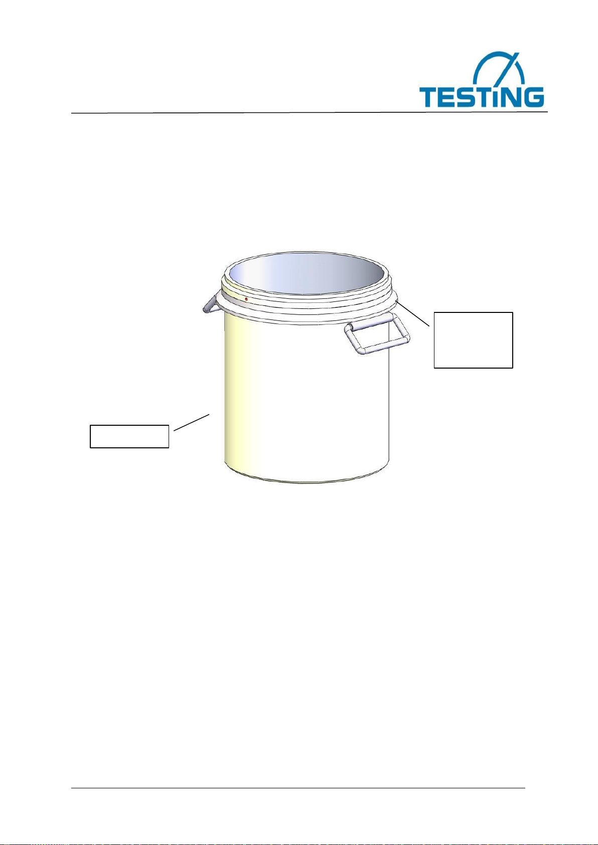
II. Test pot
Test pot for filling the material to be tested; clamping ring with handles
The outside of the air entrainment meters is an enclosure made of anodized cast
aluminium. The upper part and the test pot are held together, air-tight, by quick-release
latches. The water is filled in through the two ball shut-off valves, and air-pressure release
takes place through these same valves.
The compressed air is produced by a hand pump installed in the air entrainment meter. A
correction valve (with the black rubber cap) for setting the initial pressure and the overflow
valve (with the green rubber cap) are located on the cover of the entrainment meters. The
overflow valve and the correction valve are operated by pressing the proper buttons. The
pressure gauge is also mounted on this top part of the air entrainment meter, in a protected
position. The scale of the pressure gauge reads from 0 to 100 %.
Clamping
ring with
handles
Test pot

Air Entrainment Meters
0.5 litre; model: TESTING 1.0334 0,75 litre; model: TESTING 1.0337
1 litre; model: TESTING 1.0335 5 litre; model: TESTING 2.0332
7 litre; model: TESTING 2.0337 8 litre; model: TESTING 2.0334
Page 13 of 42 pages
Technical data for the TESTING air entrainment meters:
Filling
capacity:
0.5 litre
0.75 litre
1 litre
5 litre
7 litre
8 litre
Filling
material:
Fresh
mortar
Fresh
mortar
Fresh
mortar
Fresh
mortar
Fresh
mortar
Fresh
mortar
Display:
Pressure gauge display with readings in percent;
accuracy class = 1.0
Size:
180 dia.
x 316 mm
180 dia. x
316 mm
180 dia. x
330 mm
220 dia. x
490 mm
ø220 x 505
mm
220 dia. x
600 mm
Net weight:
3.8 kg
3.9 kg
4.0 kg
8.7 kg
9,1 kg
9.2 kg
Gross
weight:
approx.
4.8 kg
approx.
5.3 kg
approx.
6.0 kg
approx.
20.2 kg
approx.
24,6 kg
approx.
28.2 kg
Subdivision of the pressure-gauge scale for the 0.5-litre, 0.75-litre and 1-litre
TESTING air entrainment meter:
Percent by volume (%):
Percent by volume, per
subdivision (graduation):
0 ... 5
0.1
5 ... 10
0.2
10 ... 20
0.5
20 ... 30
1.0
30 ... 50
5
50 ... 100
No subdivision (no graduation)
Subdivision of the pressure-gauge scale for the 5-litre, 7-litre and 8-litre
TESTING air entrainment meters:
Percent by volume (%):
Percent by volume, per
subdivision (graduation):
0 ... 8
0.1
8 ... 15
0.5
15 ... 20
1.0
20 ... 50
5.0
50 ... 100
No subdivision (no graduation)

Air Entrainment Meters
0.5 litre; model: TESTING 1.0334 0,75 litre; model: TESTING 1.0337
1 litre; model: TESTING 1.0335 5 litre; model: TESTING 2.0332
7 litre; model: TESTING 2.0337 8 litre; model: TESTING 2.0334
Page 14 of 42 pages
2. The test procedure
Caution
Before filling the material to be tested into the test pot, make sure that
all the inner surfaces of the test pot and the cover of this pot have been
cleaned of oils, grease, fats, dust, and residue from earlier testing. Then
slightly moisten the inner surfaces of the test pot with a moistened cloth
or sponge. Only then may the new material to be tested be placed in the
test pot.
1. Take off the upper part by unfastening the quick-release latches. Set in place the
attachment ring for filling the meter (this is an optional piece of equipment: you may
not have received this part). Then use the quick-release latches to connect the test
pot and the attachment ring.
2. Fill the test pot with fresh mortar or fresh concrete in one or several layers, depending
on their consistency and the stipulations of the relevant standard. Compact the mortar
or concrete according to the relevant instructions of the standard by using a tamping
rod, other rod, or internal vibrator, or by placing the air entrainment meter on a
vibrating table. Perform the compacting in accordance with the instructions given in
EN 123507 (Luftgehaltsdruckausgleichsverfahren = air-content pressure-
compensation method), or as specified by other standards or specifications. The
mortar or concrete must be completely compacted. If mechanical vibration is used,
complete compaction is achieved when large air bubbles no longer appear on the
surface, when the surface is relatively smooth, and when it appears level. If an
attachment ring is not used, the amount of material filled into the test pot must be such
that it can be cleanly struck off with a straightedge.
3. After compaction, take off the attachment ring (if you have used one) and use a
straightedge to strike off the concrete or mortar level with the upper edge of the test
pot. Then use the smoothing trowel to smooth off the top surface.
4. Use a moist cloth or sponge to wipe clean the outer edges of the test pot, the flange,
and the connection elements.
5. Moisten the inside of the upper part and set it down into place. For the 5-litre,7-litre
and 8-litre air entrainment meters, turn the upper part until its red markings are in line
with the markings on the test pot.
6. Lock downward the two quick-release latches, mounted opposite each other, to form
an airtight seal between the upper part and the test pot.
Important: correct positioning of the quick-release latches
Air Entrainment Meters
0.5 litre; model: TESTING 1.0334 0,75 litre; model: TESTING 1.0337
1 litre; model: TESTING 1.0335 5 litre; model: TESTING 2.0332
7 litre; model: TESTING 2.0337 8 litre; model: TESTING 2.0334
Page 15 of 42 pages
Note
When the quick-release latches are not yet snapped into locking
position, but when the hooks of the clamps are already fastened into
the lower part of the air entrainment meter, the clamps should rest at
an angle of about 45° to the vertical wall of the air entrainment meter. If
the tension before snapping into place is too great (i.e., the clamps are
> 45°), this will damage the clamping ring. If the tension is not great
enough (i.e., the clamps are < 45°), the clamps will not provide enough
force to tightly seal the two parts of the air entrainment meter together
(please see the pictogram on the meter).
Adjustment of the quick-release latches:
Note
If the clamping force of the quick-release latches is not correctly set,
then adjust the clamping tension as described in the following:
Important: Each time after you adjust the clamping tension of the
quick-release latches, you must re-calibrate the air entrainment
meter.
For the 0.5; 0.75-litre and 1-litre TESTING air entrainment meter:
Adjust by making one complete turn of the hooks of the clamps.
For the 5-litre,7-litre and 8-litre TESTING air entrainment meters:
In making precision adjustment of the quick-release latches, one
complete turn of the clamp hooks can often be too much. For this
reason, turn the hook –as required –for less than one turn, then
press it toward the inside, and finally turn it into the straight, locked
position. This does not change the clamping tension. Then pull the
hook toward the front, until the nut lies flush at its limit position.
7. Open the two ball shut-off valves: A and B. They are open when their levers are
pointing upward.
8. Use the squeeze bottle to fill water into the left ball shut-off valve (A) until all the air
remaining in the unit between the top cover and the top surface of the mortar or
concrete has escaped from the air entrainment meter through the right ball shut-off
valve (B) on the opposite side. Important: Fill in the water until the water that comes
out from the right valve (B) has no air bubbles. During this step of work, tilt the air
entrainment meter to the left (see section 7. Calibration instructions, 8-litre, picture no.
6) so that the ball shut-off valve on the right side (B) points approximately vertical and
so that it provides the highest point for the air toescape from the air entrainment meter.

Air Entrainment Meters
0.5 litre; model: TESTING 1.0334 0,75 litre; model: TESTING 1.0337
1 litre; model: TESTING 1.0335 5 litre; model: TESTING 2.0332
7 litre; model: TESTING 2.0337 8 litre; model: TESTING 2.0334
Page 16 of 42 pages
9. Use a mallet or a rubber hammer to beat against the side of the air entrainment meter
so that the last remaining air bubbles will be removed. Important: It is absolutely
necessary that all air be removed from the air entrainment meter. If not all air is
removed, the reading will be incorrect, since this air pocket will be calculated as part
of the entrained air content of the mortar or concrete. Critical: The water that flows
out of the meter must absolutely have no bubbles. This means that a constant flow
of water from the squeeze bottle is necessary to remove all the air.
10. Close both the shut-off valves (A and B).
11. Turn the red ball-headed knob to the left to release (unlock) the pump piston rod of
the hand pump. Now pump up the air entrainment meter until the black pointer of the
pressure gauge slightly goes beyond the red marking pointer. This is the initial
pressure. Wait a few seconds until the air from the pressure chamber has adjusted to
the ambient temperature. If the black pointer has gone too far (i.e., past the red
marking pointer), correct the pressure by briefly pressing the CORRECTION button of
the correction valve (the black cap). Tap with your finger gently against the dial of the
pressure gauge until the pointer comes to rest. It is possible that your work until now
will have caused the black pointer to come to rest above the red marking, next to the
zero point. In this case, pump up the air entrainment meter again untilthe black pointer
is below the red marking.
Note
After you have pumped up the air entrainment meter, do NOT screw the
ball knob of the pump piston back down again. The threads under the
ball knob are provided only for safety and security during transport
–or to screw down the piston during cleaning of the air entrainment
meter so that no water can enter into the pump sleeve.
12. Press the button TEST (green rubber cap) to activate the overflow valve. This will
allow the air from the pressure chamber to flow into the test pot. Press the green TEST
button several times until the pressure has equalized. At the same time, hit the side of
the container wall hard with a rubber hammer or other suitable tool. Then tap lightly
with your finger against the pressure gauge until the pointer comes to rest.
13. Now note the apparent air entrainment reading (A1) of the fresh mortar or fresh
cement in percent.
14. After the testing is finished, slowly open both of the two ball shut-off valves. This will
allow the pressure to be released from the test pot.
15. Press the TEST button to open the overflow valve and allow the remaining air to flow
out of the pressure chamber into the test pot. At this time, the pointer of the pressure
gauge will slowly return to its initial position.
16. Open the quick-release latches and take off the upper part.
17. If required, calculate the absolute air entrainment (Ac) by application of the aggregate
correction factor. This factor (given in percent by volume) is always the same for the
same aggregate. It must therefore be determined only once in such cases.

Air Entrainment Meters
0.5 litre; model: TESTING 1.0334 0,75 litre; model: TESTING 1.0337
1 litre; model: TESTING 1.0335 5 litre; model: TESTING 2.0332
7 litre; model: TESTING 2.0337 8 litre; model: TESTING 2.0334
Page 17 of 42 pages
18. For practical reasons, it is not necessary to apply the aggregate correction factor when
you use normal and dense aggregate (G = 0). If you need to determine the aggregate
correction factor, conduct the air entrainment test with aggregate and water in the test
pot which has been filled without air (also see EN 12350-7, Attachment B).
19. The absolute air entrainment (Ac) of the sample is calculated according to the
following equation:
Ac
=
A1- G [V-%]
Ac
=
absolute air entrainment
A1
=
apparent air entrainment reading
G
=
aggregate correction factor
Caution
Please work strictly by this order, otherwise mortar or concrete may get
into the pressure chamber.
After pressure compensation, the CORRECTION button must not be
pressed under any circumstances, as otherwise sample material will
flow through the channels into the pressure chamber after the TEST
button has been pressed. This will damage the instrument and make it
unusable. The valves leak and the volume changes.
3. Cleaning and maintenance
If these air entrainment meters are properly used, they need no special maintenance.
After performing a test, carefully clean the air entrainment meter with a moist sponge, and
dry it off. Rinse the ball shut-off valves thoroughly by using the squeeze bottle to squirt
water through them. Then oil the ball shut-off valves.
Caution
Never immerse the air entrainment meter in water. The machine is
protected against spray water, but it is not waterproof.
When cleaning the air entrainment meter, be sure to lock the pump
piston rod by screwing it tightly to the right. This will prevent water from
entering the air entrainment meter through the pump.

Air Entrainment Meters
0.5 litre; model: TESTING 1.0334 0,75 litre; model: TESTING 1.0337
1 litre; model: TESTING 1.0335 5 litre; model: TESTING 2.0332
7 litre; model: TESTING 2.0337 8 litre; model: TESTING 2.0334
Page 18 of 42 pages
4. Checking and calibrating the air entrainment
4.1 Determining the initial pressure
To ensure that the air entrainment meter has the correct settings and will function properly,
please conduct the following checks:
a) When there is no pressure in the air entrainment meter, the pointer of the
pressure gauge must lie on the marking after 100 % (see Section 7. Calibration
instructions, illustration no. 4). If the pointer does not lie over this marking, open
the threaded ring of the pressure gauge. Then hold the axis of the pointer
securely, and turn the screw on the opposite side of the pointer to move the
pointer to the marking after 100 %. Please look at the possibilities of results,
nos. I to III, in Section 4.2.
b) The initial pressure is the pressure to which you have pumped up the air
entrainment meter before you begin testing. On the pressure-gauge scale, this
pressure is at the left of the zero point, and is marked by a red marking pointer.
This additional air volume will compensate for the loss of air volume during
testing of the air entrainment (this loss of air volume is due to the technical
design of the device). The initial pressure that applies to each device has
already been set and marked by the red marking pointer during factory testing,
before each air entrainment meter is shipped to its users.
For purposes of pre-setting, system characteristics require that the red marking pointer
must be placed in a position to the left of the zero point. To make this pre-setting, first
remove the threaded ring and the Plexiglas lens of the pressure gauge so that you can
move the marking pointer.
Please follow the steps below to make the correct setting of the red marking pointer:
1. Remove the upper part of the air entrainment meter (this is the part of the air
entrainment meter with the pressure-gauge mounting). Now, take the short tube that
is delivered with the air entrainment meter as part of the calibration kit, and insert it
from below into the hole that has been provided for the left ball shut-off valve (A).
2. Fill the test pot with water, up to the top.
3. Set the upper part of the air entrainment meter back onto its normal position. Place
the upper part of the unit back into place and turn it until the red points on the cover
are in line with each other (only for the 5; 7 and 8-litre air entrainment meters).
4. Fasten the upper part of the air entrainment meter firmly and airtight together with the
test pot by snapping down both of the two quick-release latches at the same time.
These clamps are located on opposite sides of the air entrainment meter.
5. Open the two ball shut-off valves (A and B). They are open when their levers are

Air Entrainment Meters
0.5 litre; model: TESTING 1.0334 0,75 litre; model: TESTING 1.0337
1 litre; model: TESTING 1.0335 5 litre; model: TESTING 2.0332
7 litre; model: TESTING 2.0337 8 litre; model: TESTING 2.0334
Page 19 of 42 pages
Caution
When the quick-release latches are not yet snapped into locking
position, but when the hooks of the clamps are already fastened into
the lower part of the air entrainment meter, the clamps should rest at
an angle of about 45° to the vertical wall of the air entrainment
meter. If the tension before snapping into place is too great (i.e., the
clamps are > 45°), this will damage the clamping ring. If the tension
is not great enough (i.e., the clamps are < 45°), the clamps will not
provide enough force to tightly seal the two parts of the air
entrainment meter together.
pointing upward.
6. Use the squeeze bottle to fill water into the left ball shut-off valve (A) until all the air
has escaped from the air entrainment meter through the right ball shut-off valve (B)
on the opposite side. To make sure that all air has escaped from the device, tilt the air
entrainment meter to the left until the right ball shut-off valve is pointing vertically (see
Section 7. Calibration instructions, picture no. 6). Important: it is absolutely
necessary that you let the water flow out of the right ball shut-off valve until it no
longer contains bubbles. To ensure that the water contains no more bubbles, it is
essential that the water continuously flows through the air entrainment meter.
7. Now close both of the ball shut-off valves (A and B).
8. Turn the ball-headed knob to the left to release (unlock) the pump piston rod of the
hand pump. Now pump up the air entrainment meter until the black pointer of the
pressure gauge is slightly behind the red marking pointer (which marks the initial
pressure). Wait a few seconds until the air in the air chamber has cooled down to room
temperature. If you have allowed the black pointer to go too far (i.e., past the red
marking pointer), correct the pressure by briefly pressing the CORRECTION button.
At the same time, tap with your finger gently against the dial of the pressure gauge
until the pointer comes to rest.
9. Activate the overflow valve by pressing the TEST button. This will allow air to flow from
the pressure chamber into the test pot. Press the TEST button several times until the
pressure has equalized. At the same time, tap with your finger gently against the dial
of the pressure gauge until the pointer comes to rest.
4.2 Results of testing for the initial pressure
The following three test results are possible:
I. If the black pressure-gauge pointer moves to 0 %, then the position of the red marking
pointer is correct (for more details, please see Section 4.3).
II. If the pressure-gauge pointer goes beyond zero (for example, to 0.1 or 0.2 %), then it
is necessary to move the red marking pointer farther to the left –i.e., in the opposite
direction –by the same % amount (in this example, 0.1 or 0.2 %):. To make this

Air Entrainment Meters
0.5 litre; model: TESTING 1.0334 0,75 litre; model: TESTING 1.0337
1 litre; model: TESTING 1.0335 5 litre; model: TESTING 2.0332
7 litre; model: TESTING 2.0337 8 litre; model: TESTING 2.0334
Page 20 of 42 pages
adjustment, first remove the threaded ring and the transparent Plexiglas cover of the
pressure gauge.
III. If the pressure-gauge pointer does not reach the zero point, then it is necessary to
move the red marking pointer farther in the direction of the zero point. To make this
adjustment, first remove the threaded ring and the transparent Plexiglas cover of the
pressure gauge.
Carefully open the right ball shut-off valve (B) to allow the pressure to escape out of the
test pot.
Now, once again perform the steps 5 to 9 of section 4.1 as described above.
If the black pressure-gauge pointer now goes to zero, the new setting position of the red
marking pointer is now correct. If the pressure-gauge pointer does not reach the zero
point, then the red marking pointer must be adjusted again, and the steps of work
described above must be repeated.
If the black pressure-gauge pointer does not come to rest, the air entrainment meter has
a leak. If this is the case, please get in touch with After-Sales Service of the manufacturer.
His company will have to test and repair the air entrainment meter as necessary.
4.3 Calibration
From time to time it is necessary to check the air entrainment readings on the pressure
gauge to make sure that they are accurate. A calibration kit has been delivered with the
air entrainment meter to check the accuracy of the readings.
Actually, we calibrate all new or repaired air entrainment meters at ourfactory, as a general
policy. You can, however, calibrate the air entrainment meter yourself, as follows:
4.3.1 Determination of the volume of the test pot:
•To calibrate the 0.75-litre TESTING air entrainment meter, you will need to take 75
g of water as test volume from the water-filled meter. This corresponds to 10 % of
the total water content of the test pot (total filling = 75 g, which is 0.75 litre = 750
cm³ of water).
•To calibrate the 0.5-litre TESTING air entrainment meter, you will need to take 50
g of water as test volume from the water-filled meter. This corresponds to 10 % of
the total water content of the test pot (total filling = 50 g, which is 0.5 litre = 500 cm³
of water).
•To calibrate the 1-litre TESTING air entrainment meter, you will need to take 100 g
of water as test volume from the water-filled meter. This corresponds to 10 % of the
total water content of the test pot (total filling = 1000 g, which is 1 litre = 1000 cm³
of water).
This manual suits for next models
5
Table of contents
Other TESTING Measuring Instrument manuals


Popular Measuring Instrument manuals by other brands


Keysight
Keysight NFA Series Security Features

pico Technology
pico Technology TA133 user manual

General
General A3G instruction manual

RDI Technology
RDI Technology M370M instruction manual

Ruskin
Ruskin RRS ROOFTOP installation instructions

LaserLiner
LaserLiner PowerCross-Laser 5 Combi operating instructions


