TESTING 7306 User manual

TESTING Bluhm & Feuerherdt GmbH
Production and Sales of
Systems for the Testing of Construction Materials
Motzener Str. 26b
DE 12277 Berlin, Germany
Tel. +49(0)30/710 96 45-0
Fax +49(0)30/710 96 45-98
www.testing.de
1
Operating Manual
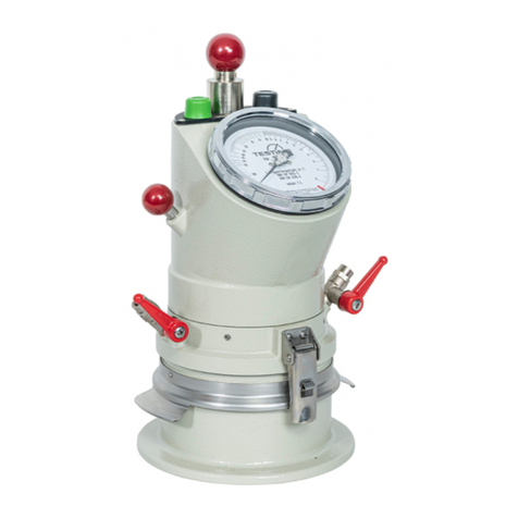
Air Pycnometer, 1 Litre
Type 7306
Equipment Number: 253

Air Pycnometer
Model 3.7306
2
Importance of this Operating Manual:
Do not place this machine into operation before you understand the function and position
of all control features.
Contents: Page
1. Basic instructions.......................................................................................................... 3
1.1 Pertinent standards and regulations .............................................................................................3
1.2 Purposes for which this device is not intended to be used ...........................................................3
1.3 Safety instructions.........................................................................................................................4
1.3.1 Obligations of the user..............................................................................................................4
1.3.2 Safety features..........................................................................................................................4
1.4 Receiving the system from the forwarding agent; transport..........................................................5
1.4.1 Receiving the system from the forwarding agent .....................................................................5
1.4.2 Transport...................................................................................................................................5
1.5 Scope of delivery...........................................................................................................................6
1.6 Description of the equipment.........................................................................................................6
2. Description of the measuring method.......................................................................... 7
3. Conduct of testing ......................................................................................................... 7
4. Evaluation of the results for water content.................................................................. 8
4.1 Calculating the water content w....................................................................................................8
4.2 Determination of the water content w by using nomographic chart no. 1.....................................9
5. Determining the grain density s................................................................................. 10
6. Additional remarks for improvement of the measurement exactness for
determination of the volume....................................................................................... 10
7. Checking the measuring accuracy............................................................................. 11
8. Air Pycnometer measurements made on cylinder samples ..................................... 12
9. Determination of water content for the Proctor test.................................................. 12
10. Care of the Air Pycnometer......................................................................................... 13
11. Adjustment of the pressure-gauge reading ............................................................... 13
12. Description of the analysis procedure (nomographic chart no. 1)........................... 14
12.1 Determination of the water content .............................................................................................14
12.2 Determination of the grain density ..............................................................................................15
12.3 Determination of various soil-mechanics parameters for soil samples taken from sampling
cylinders in accordance with DIN 18125.....................................................................................17
12.3.1 Determination of the wet soil density..................................................................................17
12.3.2 Determination of the water content ....................................................................................17
12.3.3 Determination of the air content .........................................................................................18
12.3.4 Determination of the dry density.........................................................................................18
12.3.5 Determination of the pore volume......................................................................................19
13. Correction of a volume measurement........................................................................ 20
14. Influence of temperature on the measurement results............................................. 22
15. After-sales service and spare parts............................................................................ 23
15.1 Date of issue of this Operational Manual ....................................................................................23
15.2 Copyright.....................................................................................................................................23
15.3 Contact for help and spare parts.................................................................................................23
Attachments:
Declaration of conformity
Spare-parts list
Exploded diagram and functional elements of the 1-litre manual Air Pycnometer
Sequence of operations; testing the device

Air Pycnometer
Model 3.7306
3
1. Basic instructions
1.1 Pertinent standards and regulations
This Operational Manual contains the information required for operation of the product
described here, for the purpose for which they have been designed. This Operational Man-
ual is intended to be used only by technically qualified staff.
“Technically qualified staff” is defined as those persons who – as a result of their training;
their experience; the instructions which they have received; as well as their knowledge of
the relevant standards, regulations, accident-prevention regulations, and conditions under
which the product will be operated in the company –have been authorized by the person
responsible for the safety of the company facilities and staff to carry out the activities and
actions required for operation of the equipment described below, and who can recognize
and prevent any possible dangers arising from such operation (this definition of technically
qualified staff has been provided in IEC 364).
The User must by all means observe the requirements and limit values, as well as all
safety instructions, given in this Operational Manual. Any use of this device not in con-
formity with these stipulations shall be considered to be in violation of the use for which
this system was intended. If this device must be operated under special conditions, or with
special modes of operation, then this is authorized only after consultation with the manu-
facturer, and after obtaining his prior and express approval.
The Air Pycnometer method is a test procedure which measures the following soil-me-
chanics characteristics in relatively short time:
Water content: w
Grain density
s
DIN 18125, Sheet 2, “Determination of Water Content by Fast Procedures,” describes how
to measure the water content w.
The technical testing specifications for soils and rocks, TP BF-StB, Part B 3.3, published
by the German Research Association for Roads and Transportation, describes measure-
ment of the grain density s.
The Air Pycnometer, owing to its engineering design and simple operation, is especially
well suited for use on construction sites.
This Operating Manual provides a detailed description of the conduct of testing and an
evaluation of test results, as well as a description of the monitoring possibilities to assure
the functionability of the device. The following instructions pertain to the testing of soil
samples. They apply to the Air Pycnometer with a testing volume of 1,000 ml.
1.2 Purposes for which this device is not intended to be used
This Air Pycnometer is not intended to be used for construction materials that are different
from those stated in Section 1.1 above.

Air Pycnometer
Model 3.7306
4
1.3 Safety instructions
1.3.1 Obligations of the user
This Air Pycnometer has been designed and built in accordance with the state of the en-
gineering art and with the accepted rules of good engineering practice. The use of this Air
Pycnometer, however, can cause danger to the health and safety of the User and third
parties. It can also cause damage to mechanical parts or to other objects of value.
The Operator of the Air Pycnometer is responsible to ensure that he or she does not en-
danger himself/herself or any other persons in the operation of this equipment. Only those
persons who have received instruction in the operation of this Air Pycnometer are author-
ized to operate this device alone and under their own responsibility.
If there are any malfunctions or other trouble that could cause dangerous situations to
arise in work with the Air Pycnometer, these difficulties must be corrected in all cases
before working with the machine.
The Air Pycnometer may be used only:
For the purposes for which it was intended
If it is in completely satisfactory technical condition with regard to safety in operation.
If there are any malfunctions or other trouble that could cause dangerous situations to
arise in work with the Air Pycnometer, these difficulties must be corrected in all cases
before working with the machine.
1.3.2 Safety features
Protection of the hand ump during transport
To prevent damage to the hand pump during transport, screw down the pump rod. Use
the round head with the thread to screw the pump rod into the upper part of the Air Pyc-
nometer.

Air Pycnometer
Model 3.7306
5
1.4 Receiving the system from the forwarding agent; transport
1.4.1 Receiving the system from the forwarding agent
When the system arrives from the forwarding agent, make an external inspection. If there
are no visible damages or other shortcomings, accept the consignment from the freight
forwarder (the package service or a haulage agent).
If there are no transport damages or other shortcomings, use the bill of delivery to check
to make sure that the delivery is complete.
If you believe that transport damage may have taken place when you receive the equip-
ment, or if you discover after you have accepted the delivery that damage has occurred,
immediately make a report of this damage, with an exact description of the nature and the
extent of the damage. Send this report to us immediately by fax. Important: Be sure not to
make any changes or other alterations to the system as it has been delivered.
When we receive this report, we shall decide whether we can solve the difficulty by one
of the following steps:
Delivery to you of spare parts
Sending a specialist fitter or mechanic to your company
Asking for return of the system to us for replacement or repair.
1.4.2 Transport
The Air Pycnometer is delivered in suitable carton packing. Filling material is placed in the
remaining empty spaces to prevent transport damages.
After being unpacked, use the handles to move the Air Pycnometer by hand to its place of
use.
Store the Air Pycnometer in an upright position. Do not allow the Air Pycnometer to be
subject to impacts or vibration that could harm the sensitive pressure gauge. Before
transport, be sure to screw in the pump rod as described above.
The weight is approx. 5.9 kg.

Air Pycnometer
Model 3.7306
6
1.5 Scope of delivery
Air Pycnometer
As options, at additional price:
Attachment ring for filling the meter
Transport container
Tamper and straightedge for striking off
If you request, we can deliver, as an option at extra cost, a calibration record for use as
proof of monitoring of testing equipment. This can be important as part of your quality
management system.
1.6 Description of the equipment
1 Test pot
2 Star handle
3 Correction valve for the air chamber
4 Air pump
5 Precision pressure gauge (accuracy class as per DIN 18 070)
6 Pressure equalization valve
7 Air chamber
8 Air-vent valve
Fig. 1: Schematic diagram of the Air Pycnometer

Air Pycnometer
Model 3.7306
7
2. Description of the measuring method
Fill the soil sample into the pressure-tight test pot (1). Operate the air pump (4) to build up
an air pressure of approx. 2.35 bar in the air chamber (7). Now use the correction valve
for the air chamber (3) to exactly regulate the air pressure to precisely 2.30 bar. Now op-
erate the pressure equalization valve (6) to allow the excess pressure to pass through this
valve into the test pot. A pressure between the test pot (1) and the air chamber (7) will
now develop that represents an average between these vessels. Measure this pressure
with the precision pressure gauge (5). Now use this pressure together with the nomo-
graphic charts provided with every Air Pycnometer to determine the volumes of the solid
and liquid constituents of the soil sample. Use these volume results, the mass of the wet
sample, and the known grain density to calculate the water content w.
3. Conduct of testing
First determine the mass mKof the test pot. Then fill the sample into the test pot, one layer
at a time. Use the tamper to thoroughly tamp down each layer by hand. The sample should
fill the test pot, but only up to the top edge. Next, weigh the test pot with its sample (mK+
m). Now, carefully clean and slightly moisten the top edge of the test pot and the sealing
ring. Make sure that the air-vent valve (8) is open. Place the upper part down onto the test
pot. Now turn the upper part horizontally by 90 °, and use the two star handles (2) to screw
the upper part down. The tension should be the same in the star handles. The star-shaped
heads of these threaded fastenings have markings. When they are screwed down tight,
the markings will be in the same position, pointing toward the front (i.e., toward the person
who is making the adjustments). This is necessary to prevent fluctuation of the volume of
the pot that could result from different tension in the threaded fastenings. Close valves (3)
and (8). Use the air pump (4) to create a pressure of approx. 2.35 bar in the air chamber.
Important: do NOT screw in the pump piston!
Carefully open the correction valve for the air chamber (3) and vertically knock against the
pressure-gauge lens with the Plexiglas view-direction tube. Use the correction valve to
precisely set a pressure of p0 = 2.30 bar in the air chamber. Always be sure to make this
precision correction when the pressure is falling. When you read off from the pointer of
the pressure gauge, be sure to look through the Plexiglas view-direction tube that is per-
manently attached to the gauge lens. The enclosed nomographic chart no. 1 has been
prepared for the necessary evaluation in connection with this pressure of p0 = 2.30 bar.
Next, close the correction valve for the air chamber (3). Carefully open the pressure equal-
ization valve (6) to allow the air pressure to equalize between the air chamber and the test
pot. You can tell that the pressure has been completely equalized when you knock with
the Plexiglas view-direction tube onto the pressure gauge while valve (6) is open, and the
pressure reading remains constant. While leaving the pressure equalization valve (6)
open, then enter the final, resulting air pressure p1, as shown by the precision pressure
gauge, into the record of testing.
If pressure equalization does not take place within 5 to 10 seconds, and if the pressure
continues to decrease, then the measuring device has a leak. If this is the case, open the
air-vent valve (8) of the test pot. Then take off the cover to the pot and clean the top edge
of the test pot. Also clean the rubber ring and the screw valves. Perform a new test. If

Air Pycnometer
Model 3.7306
8
pressure equalization again does not take place within 5 to 10 seconds, and if the pressure
continues to decrease as before, then check the entire Air Pycnometer for leaks. See the
instructions in Section 10 of this Operating Manual.
After the first measurement, open the air-vent valve (8) of the test pot to vent the soil
sample. To perform the second measurement, now use the air pump (4) to pump up the
pressure in the air chamber (7) to exactly 2.35 bar. Close the air-vent valve (8). Follow the
instructions given above for the first measurement to regulate the pressure to 2.30 bar by
using the correction valve for the air chamber (3). Continue the second measurement by
following the instructions given above. It is necessary to perform three measurement pro-
cedures as described above. Record the readings as p1, p2, and p3. Now determine the
mean (average) value p for purposes of total evaluation. Now determine the volume by
using nomographic chart no. 1.
After completing the measurements, open the air-vent valve (8) of the test pot. Unscrew
the threaded connection, and lift off the upper part. Finally, thoroughly clean the test pot
and the underside of the cover.
Important note:
Before testing, make sure that the temperature of the soil sample and the temperature of
the Air Pycnometer are the same as the ambient air temperature. If these temperatures
are different even by 1 °C, this can lead to pressure deviations in the two chambers, and
to faulty results. See Section 14 of this Operating Manual.
4. Evaluation of the results for water content
4.1 Calculating the water content w
Calculation of the water content is based on the fact that a two-component mixture (soil
and water) is located in the test pot. The measurement procedure determines the mass m
and the volume V of this mixture. The components of the two-component mixture have
their own specific weight . The Air Pycnometer determines the total specific weight of
both components, the so-called water-saturated grain density m. This water-saturated
grain density results from the ratio of mixture of the soil and the water. The following equa-
tion gives the water-saturated grain density m:
m=
V
m
[g/cm³] (1)
Since the pressure has been equalized in the Air Pycnometer, it is not necessary to con-
sider the content of air in the soil sample.
Use the following equation to calculate the water content wof the soil sample:
w=
)1(
ms
ms
x 100 [%] (2)
s= grain density of the mineral share of the sample

Air Pycnometer
Model 3.7306
9
4.2 Determination of the water content w by using nomographic
chart no. 1
The enclosed nomographic chart no. 1 enables determination of the water content of
soils with a grain density sof 2.65 g/cm³ (for example, sands and gravelly sand). This is
the basic reference grain density. For different densities, an adjustment factor will be nec-
essary (see example below).
Determine the water content of the soil sample as follows:
Find the intersection of the mean value of the three pressure-gauge readings on the xaxis,
and find the mass m on the y axis. Draw a horizontal line from this point of intersection to
the water-content plot. This new point of intersection will give the water content of the soil
w, in per cent.
For every deviation of the grain density sby 0.01 g/cm³ from the reference value of
2.65 g/cm³, the water content must be adjusted by applying the adjustment factor of
0.25 %. See the example below.
Example:
If the grain density sis 2.69 g/cm³, then there will be an increase in water content wby
approximately 4 x 0.25 % = approx. 1.0 %.
It is possible to use nomographic chart no. 1 to determine the dry density d, the pore
volume, and the air content in soils samples that have been collected with a standardized
sampling cylinder in accordance with DIN 18125-2, with diameter = 100 mm, height = 120
mm, and volume V = approx. ca. 850 cm³.
This makes it possible with a compacted sand subgrade (to take one example) to use only
one measurement to continuously monitor the proctor density Pr and, as a result, the
required degree of compression DPr. You can use nomographic chart no. 2 to determine
the water content wof soils and soil mixtures with grain densities
sfrom 2.50 to 3.20
g/cm³. If it is necessary to determine the water content in aggregate, you can use chart
no. 2 to read off the water content wfor the associated wet mass, along the line for the
corresponding grain density
s= 2.50 g/cm³. It is also possible to determine the water-
cement ratio.
If you determine the water content win the above-described manner, and if you find a
water content of 6 % (for example) on the lower scale, this would mean that 60 litres of
water are contained in 1,000 kg of wet aggregate. Note: Please remember that you read
off the water content at the upper graduations between the
slines 2.80 g/cm³ and
2.70 g/cm³.
The graduation lines, as main graduations, pass through all
slines. Nomographic chart
no. 2 provides the key for determination of the water content.

Air Pycnometer
Model 3.7306
10
5. Determining the grain density s
The soil sample must be completely dry (oven temperature = 105 °C). Perform the test in
accordance with the instructions under Section 3 above. The grain density sof the soil
sample is calculated as follows:
s=
V
mt
[g/cm³] (3)
Where:
mt= the dry mass
V= volume of the sample
Chart no. 1 leads the user via the mean value of the pressure-gauge readings: i.e., verti-
cally to the volume and then farther to the intersection with the dry mass of the material,
then horizontally to the scale on the left margin with the scale divisions for grain density.
Chart no. 2 has the scale for grain density a the right margin. The key for this data analysis
is given in the upper section of chart no. 2.
Note:
This conduct of testing requires a high degree of measurement exactness and simultane-
ous checking of the measurement procedures with a reference volume. If the soil sample
to be tested is delivered in earth-moist condition, then the test for grain density should take
place on the earth-moist soil sample –with the water content determined only afterward
by oven drying.
6. Additional remarks for improvement of the measurement
exactness for determination of the volume
The greater the filling volume of the soil sample in the test pot of the Air Pycnometer, the
greater the measuring exactness. When determining the grain density, the volume of the
soil sample should not be under 800 cm³. Since a dried soil sample has a large pore
volume, this pore volume must be filled by adding water (= 1.0 g/cm³).
Procedure:
1. As an example, fill 300 g of water into the empty test pot. The water should have the
same temperature as the soil sample. The fill in the dry material, while stirring, until
the material reaches to approx. 3 mm below the top edge of the test pot. Now deter-
mine the mass mtof the dry material. There are some powdery dry soils that cause a
temperature rise when they dissolve in water. In such cases, check the temperature.
Then perform the three individual measurements, and calculate the mean value for
evaluation.
As the evaluation example shows, the added 300 g of water must be subtracted from
the volume and from the mass of the soil sample in the test pot.
2. When determining the grain density of construction materials, use only the following-
described procedure, which includes the insertion of volume plates. This is because
cements, for example chemically change upon addition of water and correspondingly

Air Pycnometer
Model 3.7306
11
undergo a change in volume. Before filling the pot with the soil sample, place a refer-
ence volume (for example, 100 or 200 ml) into the empty test pot. The volume plates
can be obtained from the manufacturer. Here also, the plate volume must be sub-
tracted from the total volume.
3. If the soil to be tested has a stiff consistency, or a high consistency (for example, with
extremely plastic clay), the Air Pycnometer procedure cannot detect the closed pores.
In such cases, fill into the test pot a certain amount of water (for example, 300 g of
water) with the same temperature as the soil sample. Then reduce the soil sample into
small sizes and fill it into the test pot. Determine the total mass, and conduct the Air
Pycnometer test as described in Section 3 above.
7. Checking the measuring accuracy
The Air Pycnometer delivered has been calibrated under the following conditions: the
altitude of Berlin Germany, and exact maintenance of the same temperature in all parts of
the Air Pycnometer. With use at other altitudes, however, the volume scale will not shift.
In order to immediately check very important measurements at any time to make sure that
the volume accuracy is correct, the following is possible:
a) A volume calibration set is available for use with your Air Pycnometer, and can be
ordered from the company that makes the Air Pycnometer. This set consists of cali-
brated partial disks with the following sizes: 1 x 500, 4 x 100, 2 x 30, 1 x 20, 1 x 10,
2 x 5, 2 x 2, 2 x 1 cm³. Use this volume calibration set in a way similar to the use of
a calibrated set of weights.
Example:
Tests made to determine the grain density of a soil sample provided the averaged reading
of 1.052 bar. This corresponds to a volume of 668 ml in accordance with nomographic
chart 1. This result was checked immediately by placing partial disks with a volume of 668
ml into the test pot. If this check measurement provides the result of 1.048 bar, for exam-
ple, then the volume difference between 1.052 bar and 1.048 can be determined by means
of chart 1. The difference of the volume variation must be compensated for by the partial
disks. A check measurement should then give a pressure of 1.052 bar.
It is possible that the Air Pycnometer can give a false reading: for example, if the soil
sample, the air, and the Air Pycnometer do not have the same temperature. In such a
case, the volume calibration set can be used to immediately check the volume determina-
tion of the soil sample with a precision of 1 cm³ –and to correct this result. The volume
calibration set must be a the same temperature as the Air Pycnometer and the ambient
room temperature.
In all cases, it is important to ensure that the clamping bolts are in the correct position as
indicated, that the Air Pycnometer absolutely has no leaks, and that the reading is made
with the Plexiglas view-direction tube.
b) A volume check is also possible by filling with water that has been exactly weighed
beforehand, and that is at exactly the correct temperature. See Section 13 for an
exact description of this procedure.

Air Pycnometer
Model 3.7306
12
8. Air Pycnometer measurements made on cylinder sam-
ples
The soil material taken from a standardized sampling cylinder –in accordance with DIN
18125-2 (i.e., diameter = 100 mm and height = 120 mm) –will fit into the test pot of the Air
Pycnometer. Such standardized sampling cylinders have a volume of approx. 825 cm³.
Use a slide calliper to determine the exact volume of the cylinder. Or, the cylinder volume
can be determined from the weight of the cylinder divided by sr (specific weight of the
steel cylinder sr is = 7.85). Fill the soil sample into the test pot and determine the mass m.
After the Air Pycnometer test, the evaluation will provide the following for the soil sample,
in accordance with Section 12.3: the water content, the wet soil density, the dry soil den-
sity, the pore volume, and the air content.
If the Proctor density Pr of a soil sample is known, then the Air Pycnometer can quickly
and simply check the degree of compaction DPr on the construction site. The degree of
compaction is calculated from the following equation:
ρdensityProctor ρdensitysoilDry
DcompactionofDegree Pr
d
Pr
(4)
9. Determination of water content for the Proctor test
To make a Proctor test in accordance with DIN 18127, it is necessary to determine the
water content of the soil sample by oven drying. To avoid long drying times, it is possible
to quickly determine the water content with an Air Pycnometer on the construction site.
Proceed as follows:
Place the soil sample, still moist from the earth, in layers in the Proctor vessel. Then carry
out the water-content test as described in Section 3 here. This determines the initial water
content for the Proctor test. Then add a slight amount of water and mix the soil well. Then
conduct the second individual test.
Then conduct another water-content test in the Air Pycnometer. The line connecting the
two points from the data obtained determines –by the rise or fall of this line –whether an
additional mixture of water, or over-drying of the soil material is necessary before the third
and (finally) the fourth individual tests –including the water-content test –can be per-
formed. Here, a soil grain density of 21.65 g/cm³ is assumed as a basis. If the actual grain
density is greater or less, the Proctor curve will –for example, with s= 2.69 g/cm³ –shift
by 1.0 on the water-content line of the chart.

Air Pycnometer
Model 3.7306
13
10. Care of the Air Pycnometer
Measurement accuracy of the Air Pycnometer can be assured only if there are absolutely
no leaks in the entire system. The air pump, the valves, and the connection between the
test pot and the upper part must be absolutely tight.
It is important to immediately lock the piston of the air pump after the preliminary pressure
of approx. 2.35 bar has been reached. If the pump valve should develop a leak,the system
will prevent the pump piston from moving up and air from escaping from the upper part of
the Air Pycnometer.
You can quickly and easily find a leak by pumping the Air Pycnometer up to approx.
2.0 bar, and immersing the Air Pycnometer in water up to the lower edge of the pressure
gauge. Bubbles rising in the water will show the position of the leak.
To care for the Air Pycnometer, clean it and seal it with Vaseline. Take off the rubber rings
(valves and rubber ring a the coupling interface) and apply Vaseline thinly all around the
rings. Only the manufacturer may repair or seal the pressure gauge and the pressure-
equalization valve. If you cannot repair the leaks by the methods shown above, the Air
Pycnometer must be returned to the manufacturer for inspection.
To ensure great measuring accuracy in the Air Pycnometer measurement procedure,
careful and professional care of the precision pressure gauge is very important.
After each measuring procedure, it is important to empty the test pot immediately and
carefully clean the pot.
11. Adjustment of the pressure-gauge reading
The volume of the test pot and the reading of the pressure gauge can be influenced by the
position of the clamping bolts. The rubber sealing ring between the upper part and the test
pot allows adjustment by tightening or untightening of the two tightening bolts. First, the
Air Pycnometer must be calibrated by a qualified specialist, who then prepares a volume
scale. When this has been accomplished, the marking arrows and the number “1” on the
neck of the tightening bolt (5) will point toward the front. After allowing all parts of the Air
Pycnometer to reach the same temperature, a measurement check should be made be-
fore conduct of testing. This check is performed with the volume calibration set. If this
measurement check reveals a discrepancy with respect to the calibration scales, then it is
possible to slightly change the volume of the test pot by changing the position setting of
the tightening bolts. If the bolts are changed in this way, their position must remain the
same for all future tests.
Example: The pressure reading can be lower than the correct figure: e.g., with a volume
of 600 ml, a reading of 0.780 bar is found instead of the reading 0.784, which would be
correct from the nomographic chart. In such a case, it is possible to turn the clamping bolts
to the right, to their next marking, in order to find a valid deviating marking-arrow position.
In our example with 600 ml, it would be possible to achieve the correct pressure-gauge
reading of 0.784. This adjustment is sufficient over the entire scale range of the nomo-
graphic tables, for water-content testing when the grain density of the soil is known.

Air Pycnometer
Model 3.7306
14
12. Description of the analysis procedure (nomographic chart
no. 1)
12.1 Determination of the water content
As shown in Fig. 2 below, enter the mean value of all pressure-gauge measurements on
the xaxis. Then draw a vertical line from this value upward to intersect the plot of the test
mass (i.e., the sample weight). Then draw a horizontal line, parallel to the xaxis to intersect
the water-content plot. This intersection gives the water content in per cent. This value is
referenced to the dry mass for a grain density of the mineral share of the soil sample of s
= 2.65 g/cm³.
Water content w(in %)
Sample mass
Pressure-gauge reading
Fig. 2: Determining the water content w[in %]
Record sheet for determining the water content (example)
Air Pycnometer no.: ###
Job designation: initial calibration
Responsible for test: John Smith
Date: 06.09.20##
Sample number
Mass of the dry soil sample and of the
test pot [in g]
3327
Mass of the test pot [in g]
1707
Mass of the earth-moist sample [in g]
1620
Pressure-gauge reading [in bar]
0.891*)
Water content in accordance with nomo-
graphic chart no. 1 [in %]
10.3
*As an example, the pressure-gauge reading was determined after calibration had been performed from
nomographic chart no. 1 for an Air Pycnometer.
Volume

Air Pycnometer
Model 3.7306
15
12.2 Determination of the grain density
To improve the accuracy of testing (see Section 6 here), you should add a certain amount
of water to the dried soil sample (for example, 300 g = 300 cm³). See Fig. 3 for the following
procedure:
Find the mean value of the pressure-gauge reading on the bottom horizontal scale, and
then go vertically upward to the volume scale on the graph. Then go to the right, horizon-
tally along the volume scale, by the amount of the volume of the added water. This pro-
vides the corrected volume. Next go vertically until your line intersects the plot of the weight
of dried sample (dry mass). Then go horizontally to the left to the scale at the far left side
of the graph, for the weight per unit volume (specific gravity).
Mass of the dry sample
Volume
Addition of water =
subtraction
Pressure-gauge reading
Fig. 3: Determining the weight per unit volume (specific gravity)
Determination of the grain density
Air Pycnometer no.: ###
Job designation: initial calibration
Responsible for test: John Smith
Date: 06.09.20##
Sample number
Mass of the dry soil sample and
test pot [in g]
3361
Mass of the test pot [in g]
1707
Dry mass of the soil sample (mt)[in g]
1654
First pressure-gauge reading [in bar]
0.769
Volume in accordance with chart no.
1 [in cm³]. If less than 800 cm³, see
point [1] below.
620
Grain density [in g/cm³]
2.665
More accurate volume determination by addition of water
Addition of water [in g]
200
s

Air Pycnometer
Model 3.7306
16
2. Pressure-gauge reading [in bar]
1129*)
Volume according to nomographic
chart no. 1
822
More accurate volume after subtrac-
tion of the additional water volume V'
622
Specific gravity in accordance with
nomographic chart no. 1
2.66
*As an example, the pressure-gauge reading was determined after calibration had been performed from
nomographic chart no. 1 for an Air Pycnometer.

Air Pycnometer
Model 3.7306
17
12.3 Determination of various soil-mechanics parameters for soil
samples taken from sampling cylinders in accordance with
DIN 18125
12.3.1 Determination of the wet soil density
Analysis procedure:
Start by finding the volume (sampling cylinder plus soil sample) on the horizontal volume
scale. Then go vertically upward to the wet mass. Now go horizontally to the left to the left
side of the graph and read off the wet density , which consists of soil, water, and air
constituents (see Fig. 4 below).
Wet mass of the
sample taken
Volume of sample taken
Fig. 4: Determination of wet density
12.3.2 Determination of the water content
Determine the water content as described under Section 12.1.
For further analysis, use the wet bulk density without air fraction () as a theoretical auxil-
iary value on the horizontal scale (intersection of sample mass and water content). Pro-
ceed the same on the left scale for dry density.
Sample mass (see 1)
See 3a
Volume containing air
Volume not containing air
Pressure-gauge reading
Fig. 5: Determination of the water content
d
n

Air Pycnometer
Model 3.7306
18
12.3.3 Determination of the air content
The air content is read off as following, by using Fig. 6: Take a horizontal line from dto
the point where it intersects the rising parabolic line from the initial point in: i.e., along the
plot of the sample mass. From where the lines nand dintersect, go vertically up to the
air-content scale, and read off the air content there.
Air content in volume % L %
Fig. 6: Determination of the air content
12.3.4 Determination of the dry density
Determine the dry density (d) of the sample taken by the following procedure: Take a
horizontal line from auxiliary value dthrough the water-content line to make an intersec-
tion on the right side of the dry-density scale at the value dt. Since this value does not
include the air content, locate it on the density scale, and extend its horizontal line from
there vertically, from the air content to the intersection.
1. From this intersection, the parabolic line leads downward to the left density scale to the
left density scale. This intersection on the left density scale gives the required dry den-
sity d.
Fig. 7: Determination of the dry density
d
n
ft
dt
d

Air Pycnometer
Model 3.7306
19
12.3.5 Determination of the pore volume
You can read off the pore volume at the right side of the graph, at the density scale, at the
level of the dfound here. In other words: the pore-volume scale (n) rises in scale values
from the bottom to the top.
Fig. 8: Determination of the pore volume
d
dt

Air Pycnometer
Model 3.7306
20
13. Correction of a volume measurement
The best checking of a volume measurement takes place with the aid of a volume calibra-
tion set. If you do not have a volume calibration set, you can also check the volume meas-
urement with an exactly weighed quantity of water, as follows:
Perform the measurement.
Empty the test pot and clean it.
Fill the test pot with water and determine the volume as described in Section 3.
Example 1:
Testing of a soil sample, with a mean pressure-gauge reading of 1.252 bar on chart no. 1,
resulted in a volume of 824 ml (V1). A verification measurement was then made to confirm
this result, by weighting 824 g of water. The pressure-gauge reading then showed 1.257
bar, instead of 1.252 bar. This check means that the soil sample has a volume less than
824 ml.
Correction now takes place asfollows: The reading of the measurementfor the soil sample
showed a value of 1.252 bar. According to chart no. 1, this results in a volume of 824 ml.
The verification measurement showed a value of 1.257 bar. According to chart no. 1, this
results in a volume of 826 ml. These results provide a correction of 0.005 bar, which means
a volume of 2 ml. Subtract 2 ml from the volume determined in the first measurement. This
now means that the actual volume of the soil test is 822 ml.
Example 2:
The verification measurement for the water filling resulted in a lower value: e.g., 1.247 bar
instead of 1.252 bar in the test made on the soil sample. This means that the volume of
the soil sample is larger than the volume of the water filled into the pot for checking and
correction. Chart no. 1 shows that the volume difference between 1.252 bar and 1.247 bar
is as follows: 824 ml minus 818 ml = 6 ml. This 6 ml is the correction amount that must
be added: 824 ml plus 6 ml = 830 ml, which is the corrected and actual volume of the soil
sample.
This manual suits for next models
1
Table of contents
Other TESTING Measuring Instrument manuals
Popular Measuring Instrument manuals by other brands

Keysight
Keysight NFA Series Security Features
pico Technology
pico Technology TA133 user manual
General
General A3G instruction manual

RDI Technology
RDI Technology M370M instruction manual
Ruskin
Ruskin RRS ROOFTOP installation instructions
LaserLiner
LaserLiner PowerCross-Laser 5 Combi operating instructions
