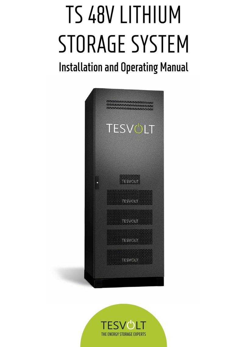
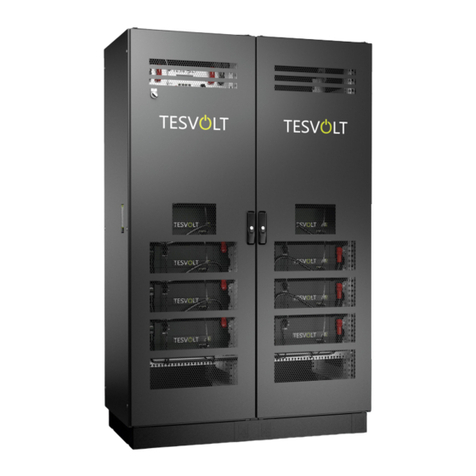
TESVOLT TS Series User manual

Installation instructionsTS series


Installation instructionsTESVOLT TS seriesincl. connection of the TS Series to SMA productswww.tesvolt.com1TS25TS40TS50E.IA..ENG-TSA.6

Table of ContentsE.IA..ENG-TSA.612 2.1 2.2345678 8.1 8.1.1 8.1.2 8.2 8.2.1 8.2.2 8.2.391011 11.1 11.212131415161718About this document Safety Qualification of the technical specialists Safty informationNeeded toolsTransport at end-customer site Installation location Scope of delivery Data sheet Installation overview Charge control System without backup power function System with backup power supply Battery storage Installation diagram TESVOLT TS APU-Unit connections Installation stepsCommissioning Decommissioning Storage system expansion Power expansion by SMA battery inverter Energy expansion by TESVOLT storage systemRemote monitoring via Sunny Portal Menu structure of Batterie Monitoring (BatMon) Battery system error and warning messages Maintenance and storageGuidelines for Handling Lithium-Batteries DisposalContact344456678891526262728293435353638394041414242www.tesvolt.com26

Scope of validity:This document applies to the following storage systems from TESVOLT GmbH:TS system in connection with Sunny Island (48V)Target groups: : This document is intended exclusively for qualified technical specialists. The instructions and actions specified in this document may only be carried out by appropriately qualified personnel. The following battery inverters may be used:ManufacturerSMA Solar Technology AGUseful Installation and planning information is available at the SMA website (www.sma.de). We recommend the following documents. Installation – Quick start – SMA FLEXIBLE STORAGE SYSTEM – Energy consumption optimisation Installation – Quick start – SMA FLEXIBLE STORAGE SYSTEM – backup power supply function Planning guideline – SMA FLEXIBLE STORAGE SYSTEM with backup power supply functionSMA, SUNNY ISLAND and SUNNYPORTAL are registered trademarks of SMA Solar Technology AG in many countries.1 About this document WARNING! This document applies to storage systems from the TESVOLT company. It provides installation support for authorised and qualified personnel. It does not replace the complete instructions of the manufacturer SMA, and these must still be observed.TypeSunny Island 3.0MSMA Solar Technology AGSunny Island 4.4MSMA Solar Technology AGSunny Island 6.0HSMA Solar Technology AGSunny Island 8.0Hwww.tesvolt.com3Explanation of used symbols:E.IA..ENG-TSA.6General warningsignsWarningelectricaltensionWarningcorrosivesubstancesWarningabout strikingtensionGeneralinformation signsSee operatinginstructionsIEC 60417-5036/5416
Caution: Risk of electricshock, auto-scheduleddischarge of energystorage system.

2.1 Qualification of the technical specialistsThe instructions in this document may only be performed by appropriately qualified technical specialists. The technical specialists must possess the following qualifications:• Training in dealing with the hazards associated with the installation and operation of electrical equipment and batteries• Training in the installation and commissioning of electrical equipment• Knowledge of, and adherence to the locally applicable connection requirements, standards and directives• Knowledge of the handling procedures and hazard sources associated with transporting, storing and disposing of Lithium-Ion batteries• Knowledge of, and adherence to this document and the associated product documentation, including all safety instructions Participation in TESVOLT certification trainings 2.2 Safety information www.tesvolt.com2 SafetyWARNING! Lethal electric shock from damaged components or pole short-circuits: Bridging the battery poles causes a short-circuit resulting in a large flow of electrical current. This short-circuit must be avoided at all costs. Use insulated tools Never place tools or metal components on the battery Always remove watches, rings and all other metal jewellery when working on the batteries Never install or operate the battery pack in potentially explosive environments or areas with relatively high humidity levels Always first switch off the charge controller and then switch off all voltage supplies to the battery before commencing work on the storage system4E.IA..ENG-TSA.6

WARNING! Acid burns and poisoning from the battery electrolyte or poisonous gases: Electrolyte or poisonous gases cannot escape from the battery pack under normal operating conditions. Despite careful design and manufacture, damage to the battery pack resulting from fault can result in escaping electrolyte or low concentrations of poisonous gases, organic solvent gases and hydrogen fluoride acids.Store the batterypack in a dry place and within the temperature range specified in the data sheet. Do not allow the battery pack to fall down Do not open the battery pack Never install or operate the battery pack in potentially explosive environments or areas with relatively high humidity levels In the case of contact with electrolyte, immediately wash the affected area with water and seek medical advicewww.tesvolt.com3 Needed tools5Needed ToolsDescriptionBattery13 mm attachment for the battery poles and APU connections
Torque wrench
For fixing the battery modules and APU in the battery cabinet
Cross-head screwdriver
Optional: For removing the cover of the battery rack
8 mm hex key
Optional: For moving the cable entry on the cover of the battery rack
TX 25 Torx screwdriver
Optional: For removing the side panels of the battery rack
TX 30 Torx screwdriver
For connecting the control and measuring cables to the Sunny Island terminal
Slot-head screwdriver
Sunny IslandFor mounting the Sunny Island wall bracket
Power drill and drill bits
For removing the cover of the Sunny Island
5 mm hex key
For crimping the lugs of the DC cable
50 to 120 sq. mm crimping pliers
For crimping the wire end ferrules
Ferrule crimper
For measuring the grid and battery voltage
Voltage measuring device
Battery+Sunny IslandE.IA..ENG-TSA.6

The delivered goods must always be checked for completeness and visible signs of damage.6 Scope of deliverywww.tesvolt.comPositionADescriptionBattery module incl. ABOBAPU incl. Cable connection set APU to 1st Battery moduleCInstallation instructionsD48 V Cable connection set (included 2x Copper bars,, 1x Patch cabel, 2x Rack Balancing Plug)ETS 25, 40 or 50 Rack FOptional: Cable connection set to Sunny Island6 The battery cabinet functions in temperatures from 0°C to 40°C and at a maximum humidity of 70%. Rooms that do not provide these conditions must be air-conditioned. The battery cabinet may not be exposed to corrosive atmospheres. If the battery cabinet is to be used in coastal areas or on farms, appropriate structural modifications to the installation room must be made to ensure hazard-free operation of the storage system.In regions subject to flooding, care must be taken to ensure that the battery cabinet is installed in a suitably elevated location that cannot be reached by flood water.The battery cabinet must not be exposed to direct sunlight. It should also not be placed in the direct vicinity of heat sources, such as an oven or a fireplace.The storage system must be set up in a fire-proof room that is free of fire loads and is separated by a class F30 fire door.5 Installation location The individual components of the TS series can weigh up to 120 kg and therefore should not be transported by a single person. It is recommended that the system is installed by at least two people. The assistance of a hand truck is helpful. No more than 5 battery modules should be stored on top of one another. WARNING! Battery modules are heavy, please ensure safe installation. Use suitable means of transport only! RIGHTWRONG4 Transport at end-customer siteE.IA..ENG-TSA.6

7www.tesvolt.com7 Technical data sheet E.IA..ENG-TSA.6OFF-GRID OR ON-GRID

8.1 Charge controlling8www.tesvolt.com8 Installation OverviewFigure: Block circuit diagram (example with backup power function, single phase)ComponentsFunctionSunny Island Battery inverter Remote ControlSunny Island display TESVOLT TSBattery cabinetHome ManagerTransmits readings from the storage system and PV installation to the Sunny Portal and is responsible for energy management, e.g. by controlling outlets Energy Meter Load meter for determining consumption or feed-in (integrated in the Home Manager 2.0)Router Connects the individual network participants Grid disconnectionDisconnects the storage system from the public grid when the emergency power function is activated in order to prevent energy from being fed back into the gridPhase couplingIn single-phase storage systems, all three outer conductors are bridged and thus supplied with power. However, phase-shifted alternating current is not provided.E.IA..ENG-TSA.6

Figure 2: Wiring of SMAFlexible Storage System for TN and TT systems with 1 Sunny Island8.1.1 System without backup power functionSystem with 1 Sunny Island9www.tesvolt.comE.IA..ENG-TSA.6

Sunny Island connection10www.tesvolt.comE.IA..ENG-TSA.6

11www.tesvolt.comPositionADescription/NoteDescriptionAC power cableConnection AC2 Gen/Grid Terminals L, NTT and PEConnection to the public mains grid via a 3-core cableConductor cross-section: 6 mm² … 16 mm²BProtective earthingconductorsConnection AC1 Loads/SunnyBoys Terminal PEAdditional earth when the conductor cross-section of the AC power cable is less than 10 mm². The conductor cross-section must be at least the same as the conductor cross-section of the AC power cable. Battery connection:Conductor cross-section: 50 mm² ... 120 mm²Cable diameter: 14 mm ... 25 mmTightening torque: 12 Nmcabel DC –cabel DC +ECDBattery temperature sensormeasuring cableConnection BatTmpOnly Lead-acid batteries require connection of a battery temperature sensor. The battery temperature sensor must be mounted in the middle of the battery array, in the upper third of the battery cell.FSunny Remote Control data cable Connection DisplayGSpeedwire network cable
Connection ComETH The Speedwire data module (SWDMSI-NR 10) must be installed in the Sunny Island in order to connect the router/switch (see Installation instructions for the Speedwire data module SWDMSI-NR 10). The ComETH connection is located on the data module.
HData cable to Lithium-IonbatteryComSync In connectionConnection for the Lithium Ion Battery Management SystemThe communication bus must be connected to theLithium-Ion battery and the termination resistor must beplugged into the ComSync Out connection.SMA, SUNNY ISLAND and SUNNYPORTAL are registered trademarks of SMA Solar Technology AG in many countries.E.IA..ENG-TSA.6

System with3 Sunny IslandsFigure 3: SMA Flexible Storage System for TN and TT systems with 3 Sunny Islands12www.tesvolt.comSMA, SUNNY ISLAND and SUNNYPORTAL are registered trademarks of SMA Solar Technology AG in many countries.E.IA..ENG-TSA.6

Master connection13www.tesvolt.comPositionADescription/NoteDescriptionAC power cableConnection AC2 Gen/Grid Terminals L, NTT and PE Connection to the public mains grid via a 3-core cable to external conductor L1Conductor cross-section: 6 mm² … 16 mm²BProtective earthingconductorConnection AC1 Loads/SunnyBoys Terminal PEAdditional earth when the conductor cross-section of the AC-power cable is less than 10 mm². The conductor cross-section must be at least the same as the conductor cross-section of the AC power cable.Battery connectionConductor cross-section: 50 mm² … 120 mm²Cable diameter: 14 mm … 25 mmTightening torque: 12 Nmcabel DC –cabel DC +ECDBattery temperature sensormeasuring cableConnection BatTmpOnly Lead-acid batteries require connection of a battery temperature sensor. The battery temperature sensor must be mounted in the middle of the battery array, in the upper third of the battery cell.FSunny Remote Control data cableConnection Display+_+_E.IA..ENG-TSA.6

Slave 1 and Slave 2 connection
+_+_GSpeedwire network cable
Connection ComETHThe Speedwire data module (SWDMSI-NR 10) with the ComETH connection must be installed in the Sunny Island in order to connect the router/switch (see Installation instructions for the Speedwire data moduleSWDMSI-NR 10).
HData cable to Lithium-Ionbattery ComSync In connectionConnection for the Lithium Ion Battery Management System. The communication bus must be connected to the Lithium-Ion battery. If Lithium-Ion batteries are not used, plug the termination resistor into the ComSync In connection.14www.tesvolt.comIData cable for internalcommunication within theClusterComSync Out connectionInternal communication bus connection from Slave 1E.IA..ENG-TSA.6

During a main grid failure, a backup power supply system with a Sunny Island provides consumers with energy and a grid-connected PV system with voltage. In the case of a grid failure a switching unit disconnects the backup power supply grid from the public mains grid. After disconnection the electrical consumers and the PV system are usually not supplied for 3 to 5 seconds. After this, the storage system can once more supply effective power and reactive power. The storage system supplies the consumers with energy, the PV system can synchronise with the backup power supply grid and generate energy again.When the public mains grid is once more available, the backup power supply system synchronises the backup power supply grid to the public mains grid. After successful synchronisation the switching unit switches the backup power supply grid to the public mains grid. When the switching unit is connected to the public mains grid the backup power supply system uses the battery for energy consumption optimisation. You can install and wire up your own switching unit or obtain a pre-wired unit from TESVOLT.15www.tesvolt.comPositionADescription/NoteDescriptionAC power cableConnection AC2 Gen/Grid Terminals L, NTT and PE,connection to the public mains grid via a 3-core cable Connect Slave 1 to external conductor L2, Slave 2 to external conductor L3. Conductor cross-section: 6 mm² ... 16 mm²BProtective earthing conductorConnection AC1 Loads/SunnyBoys Terminal PEAdditional earth when the conductor cross-section of the AC power cable is less than 10 mm². The conductor cross-section must be at least the sameas the conductor cross-section of the AC power cable.Battery connectionConductor cross-section: 50 mm² ... 120 mm²Cable diameter: 14 mm ... 25 mmTightening torque: 12 Nmcabel DC –cabel DC +ECDFData cable for internalcommunication within theClusterComSync In connectionFor Slave 1: Internal communication bus connection from the MasterFor Slave 2: Internal communication bus connection from Slave 1Data cable for internalcommunication within theClusterComSync Out connectionFor Slave 1: Internal communication bus connection to Slave 2For Slave 2: Leave the termination resistor plugged in.Slave 2 is only connected to Slave 1.8.1.2 System with backup power supplyE.IA..ENG-TSA.6

16www.tesvolt.comIMPORTANT! In order to continue operation of the PV system during backup power supply operation, care must be taken to ensure that the inverter topology matches the backup power supply grid.Accordingly, only single phase inverters should be used in a single phase backup power supply system because the backup power supply does not implement phase shifting.True 3-phase power is provided in a system with 3 Sunny Islands so that 3-phase PV inverters can also generate energy under backup power.INFORMATION Connecting consumers and the PV system:The switching unit is not a distribution system for the consumers or the PV system. You must install all necessary additional protective devices for the consumers and the PV system.E.IA..ENG-TSA.6

Single phase backup power supply systemFigure 4: Circuit diagram of a single phase switching unit with all-pole disconnection17www.tesvolt.comSMA, SUNNY ISLAND and SUNNYPORTAL are registered trademarks of SMA Solar Technology AG in many countries.E.IA..ENG-TSA.6

Backup power supply system with 1 Sunny IslandFigure 5: Interconnection overview: Connection of the single phase switching unit with all-terminal disconnection (e.g. for Germany)18www.tesvolt.comSMA, SUNNY ISLAND and SUNNYPORTAL are registered trademarks of SMA Solar Technology AG in many countriesE.IA..ENG-TSA.6
This manual suits for next models
3
Table of contents
Other TESVOLT Storage manuals
