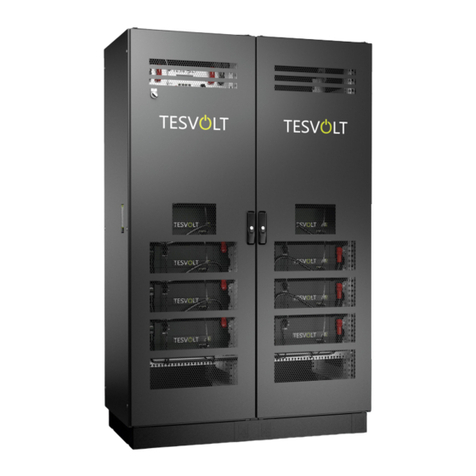
TESVOLT TS25 User manual

Installation Manual
TS 48 V


Installation Manual
TESVOLT TS 48 V
incl. connection of the TS Series to SMA products
TS 25 TS 40 TS 50
www.tesvolt.com
1
E.IA. .ENG-TS A.11

1
2
2.1
2.2
3
4
5
6
7
7.2
7.4
11
11.1
11.3
12
13
14
15
16
17
About this document
Safety
Qualification of the technical specialists
Safty information
Needed tools
Transport at end-customer site
Installation location
Technical Datasheet
Battery storage TS
Scope of delivery
Installation steps
Commissioning
Decommissioning
Storage system expansion
Energy expansion by TESVOLT storage system
Power expansion by SMA battery inverter
TESVOLT Battery Monitoring (BatMon) Software
Battery system error and warning messages
Maintenance and storage
Information on handling lithium batteries
Disposal
Contact
8 Sunny Island connection
7.1 Schematic sketch
11.2 Properly installing the addressing switch of the Active Power Unit (APU)
Connections Active Power Unit (APU) to SMA Sunny Island
9
11
7.5 E-Stop-Contact 14
15
9
10
17
19
20
20
22
23
12.1 Views and features of TESVOLT Battery Monitoring (BatMon) software
13.2 Menu structure of Battery Monitoring (BatMon)
25
27
28
29
29
30
30
25
7.3 10
www.tesvolt.com
2
Table of Contents
E.IA. .ENG-TS A.11

Scope of validity:
This document applies to the following storage systems from TESVOLT GmbH:
TS system in connection with Sunny Island (48V)
Target groups:
This document is intended exclusively for qualified technical specialists. The instructions and actions specified in this
document may only be carried out by appropriately qualified personel:
The following battery inverters may be used:
Manufacturer
Useful installation and planning information is available at SMA website (www.sma.de).
We recommend the following documents:
System Description – SMA flexible Storage System – Increased self-consumption with Sunny Island
System Description – SMA flexible Storage System – with Battery Backup function
System Description – SMA flexible Storage System – Off-Grid Systems
Operating Maunal – Sunny Island 4.4M / 6.0H / 8.0H
SMA, SUNNY ISLAND and SUNNYPORTAL are registered trademarks of SMA Solar Technology AG in many countries.
1 About this document
WARNING!
This document applies to TESVOLT storage systems. It provides qualified individuals with support during the installation
process. It does not replace the complete instructions provided by the manufacturer SMA, which must still be observed.
The TESVOLT storage system may only be used as intended.
Type
SMA Solar Technology AG Sunny Island 4.4M
SMA Solar Technology AG Sunny Island 6.0H
SMA Solar Technology AG Sunny Island 8.0H
Explanation of used symbols:
General warning
signs
Warning
electrical
tension
Warning
corrosive
substances
Warning
about striking
tension
General
information signs
See operating
instructions
IEC 60417-5036/5416
Caution: Risk of electric shock,
auto-scheduled discharge of energy
storage system.
Warnung vor
explodierenden
Teilen
Wear eye
protection
In case of contact
with eyes, rinse
thoroughly and
consult a physician
Handling near
open flame
is prohibited
Do not remove
or disassemble
the cover
www.tesvolt.com
3
E.IA. .ENG-TS A.11

2 Safety
2.1 Qualification of the technical specialists
The instructions in this document may only be performed by appropriately qualified technical specialists. The technical
specialists must possess the following qualifications:
• Training in dealing with the hazards associated with the installation and operation of electrical equipment and batteries
• Training in the installation and commissioning of electrical equipment
• Knowledge of, and adherence to the locally applicable connection requirements, standards and directives
• Knowledge of the handling procedures and hazard sources associated with transporting, storing and disposing
of Lithium-Ion batteries
• Knowledge of, and adherence to this document and the associated product documentation, including all safety instructions
Participation in TESVOLT certification trainings TS 48 Volt•
2.2 Safety information
WARNING!
Lethal electric shock from damaged components or pole short-circuits:
Bridging the battery poles causes a short-circuit resulting in a large flow of electrical current. This short-circuit must be
avoided at all costs.
Use insulated tools
Never place tools or metal components on the battery
Always remove watches, rings and all other metal jewellery when working on the batteries
Never install or operate the battery pack in potentially explosive environments or areas
with relatively high humidity levels
Always first switch off the charge controller and then switch off all voltage supplies to the battery
before commencing work on the storage system
www.tesvolt.com
4
E.IA. .ENG-TS A.11

3 Needed tools
WARNING!
Acid burns and poisoning from the battery electrolyte or poisonous gases:
Electrolyte or poisonous gases cannot escape from the battery pack under normal operating conditions. Despite
careful design and manufacture, damage to the battery pack resulting from fault can result in escaping electrolyte or
low concentrations of poisonous gases, organic solvent gases and hydrogen fluoride acids.
Store the batterypack in a dry place and within the temperature range specified in the datasheet.
Do not allow the battery pack to fall down
Do not open the battery pack
Never install or operate the battery pack in potentially explosive
environments or areas with relatively high humidity levels
In the case of contact with electrolyte, immediately wash the affected
area with water and seek medical advice
Needed Tools Description
Battery
13 mm attachment for the battery poles and APU connections
Torque wrench
For fixing the battery modules and APU in the battery cabinet
Cross-head screwdriver
Optional: For removing the cover of the battery rack
8 mm hex key
Optional: For moving the cable entry on the cover
of the battery rack
TX 25 Torx screwdriver
Optional: For removing the side panels of the battery rack
TX 30 Torx screwdriver
For connecting the control and measuring cables
to the Sunny Island terminal
Slot-head screwdriver
Sunny Island
For mounting the Sunny Island wall bracket
Power drill and drill bits
For removing the cover of the Sunny Island
5 mm hex key
For crimping the lugs of the DC cable
50 to 120 sq. mm crimping pliers
For crimping the wire end ferrules
Ferrule crimper
For measuring the grid and battery voltage
(operating voltage up to 60 V (DC) for TS 48 V)
Voltage measuring device
Battery+
Sunny Island
www.tesvolt.com
5
E.IA. .ENG-TS A.11

The battery cabinet functions in temperatures from -10°C to 50°C and at a maximum humidity of 85%. Rooms that do not provide
these conditions must be air-conditioned. The battery cabinet may not be exposed to corrosive atmospheres. If the battery cabinet
is to be used in coastal areas or on farms, appropriate structural modifications to the installation room must be made to ensure
hazard-free operation of the storage system.
The battery cabinet must not be exposed to direct sunlight. It should also not be placed in the direct vicinity of heat sources, such as
an oven or a fireplace.
In areas prone to flooding, the battery cabinet must always be installed in an elevated location where it cannot be reached by
flooding. The storage system should be installed in a fire-proof room that is free of fire loads and is sealed with a class F30 fire door.
5 Installation location
The individual components of the TS series can weigh up to 120 kg and therefore should not be transported by a single person. It is
recommended that the system is installed by at least two people. The assistance of a hand truck is helpful. No more than 5 battery
modules should be stored on top of one another.
WARNING!
Battery modules are heavy (36kg). Please ensure safe installation. Use suitable means of transport only!
Right Wrong
4 Transport at end-customer site
www.tesvolt.com
6
E.IA. .ENG-TS A.11

6 Technical Datasheet
OFF-GRID or ON-GRID
7
www.tesvolt.com
IEC 61000-6-1/2/3/4
47.6 to 58.1V
10-year capacity guarantee, 5-year system guarantee
TESVOLT offers free return of batteries from Germany
3 watt (complete system TS)
E.IA. .ENG-TS A.11

The battery modules (ABO) and the Active Power Unit (APU) are delivered in cartons on pallets separate from the battery
rack. The scope of delivery should be checked against the delivery note and the requirements under point 4 “Transport at
end-customer site” and point 5 “Installation location” must be observed.
7.1 Schematic sketch
7 Battery storage TS
8
www.tesvolt.com
Installation Manual
E
(z.B. TS 40 Rack)
E.IA. .ENG-TS A.11

The delivered goods must always be checked for completeness and visible signs of damage.
Position Description
7.2 Scope of delivery
Components
ABattery module
incl. Active Battery Optimizer (ABO)
B
C
D
E
FGround cable including fixing material for connection
on the provided grounding studs
Active Power Unit (APU)
incl. Cable connection set
to the APU to 1st Battery module
Installation Manual
48 V Cable connection set
(included 2x Copper bars, 1x Patch cabel,
2x Rack Balancing Plug)
TS 25, TS 40 or TS 50 Rack
G
Optional:
Cable connection set for connecting the battery
to the Sunny Island
9
www.tesvolt.com
Installation Manual
E.IA. .ENG-TS A.11

7.3 Connecting Active Power Unit (APU) to SMA Sunny Island
Labeling
Charger +
Description
DC connection for the positive pole of the Sunny Island
Charger - DC connection for the negative pole of the Sunny Island
Battery + DC connection for the positive pole of the 1st battery module
Battery - DC connection for the negative pole of the 1st battery module
Switch On/off switch for the battery
E-Stop Two-pin plug for the optional connection of an emergency off switch.
APU Fuse (F1)
CAN SMA
CAN port for communication between the battery and the Sunny Island.
Connection to the Sunny Island (master) ComSyncIn (single-cluster) or connection
to the Sunny Island (slave 2) ComSyncOut (multi-cluster)
LAN When connecting to an existing network with DHCP, the battery
can be monitored using BatMon. The master/slave communication occurs
over the LAN connection.
Address Rotary switch for adjusting the battery’s master/slave connections.
Further information can be found under point 11.2
BAT COM Communication link to the battery module. Connect the BAT COM of the APU
to the BAT COM IN of the first battery module.
TERM
OFFON
CAN OUTCAN IN CAN SMA LAN BAT COM
SWITCH APU FUSE (F1)
BATTERY + CHARGER + E-STOPCHARGER - BATTERY -TERM
ON / OFF
CAN
IN
CAN
OUT
CAN
SMA
LAN ADDRESS BAT COM
10
www.tesvolt.com
CAN bus termination. TERM must be activated (ON) for the last CAN bus participant.
Fuse element to protect the APU (2a time-delay fuse (T) 5x20mm, in accordance with
DIN41571-2, type 521.000 from ESKA, 250VAC)
APU Master / Slave Communication
APU Master / Slave Communication
E.IA. .ENG-TS A.11

Position the battery cabinet in the installation location, taking into account the
requirements listed under point 5
Open the door of the battery cabinet using the included control cabinet key,
which can be found on the outside of the door.
Connect the earth to the battery cabinet at one of the earthing bolts provided.
Step Description/Note
View
7.4 Installation steps
Mount the APU on the upper slide rail and use screws to fix it in place at the four
fastening points. The two-pin plug for the e-stop connection to the APU must be
plugged in upon delivery. Until this is plugged in, the APU remains inactive.
Further information on the e-stop can be found under 7.5 of this Installation
Manual.
WARNING!
Installation and servicing may only be performed by qualified personnel. Only authorised TESVOLT personnel are
permitted to open the APU-Unit. Improper use or incorrect configuration may damage the APU-Unit.
Opening the APU voids the warranty.
1
2
3
4
>>
11
www.tesvolt.com
E.IA. .ENG-TS A.11

Step View
5
6
7
8
9
Insert the battery modules into the provided slide rails. From top to bottom.
Gently break out the intended breaking areas for the copper tracks at the
top of the cover (+). A combination drill can be used to help.
The cover is prepared for a re-assembly after uncovered passage for
the copper rails to be mounted.
Connect the DC copper rails, always bearing in mind that in the 48V variation,
the positive pole must touch the positive pole and the negative pole must touch
the negative pole. Tighten the 13mm screws using 12nm of torque.
>>
Description/Note
12
www.tesvolt.com
Remove the side covers of the ABO from the battery module as follows:
1 = loosen the clamp
2 = pull slightly downwards
3 = over the outer wall of the cabinet
3
2
1
E.IA. .ENG-TS A.11

Step View
10
12
11
13
14
Mount the ABO side covers on the battery modules.
Lay the communication cable for the BAT COM using the included patch cable.
Start by running the cable from the APU (BAT COM) to the BAT COM IN of the
battery module installed below the APU. From there, run the cable from the
BAT COM OUT to the BAT COM IN of the next module, etc.
Plug in the rack balancing plugs (unless these were already plugged in upon
delivery). The plug with an internal bridge from 1 to 4 is plugged into Rack
Balancing In. The plug with an internal bridge from 1 to 2 is plugged into Rack
Balancing Out.
Connect the DC cable from the Sunny Island to the APU (CHARGER).
If you do not use pre-assembled cables from TESVOLT, it is important that an
earth leakage and short-circuit protected cable (such as NSGAFöU) are used.
Connect the communication cable from the Sunny Island (ComSyncIn)
to the APU (CAN SMA)
Installation completed!
Description/Note
13
www.tesvolt.com
E.IA. .ENG-TS A.11

The e-stop (emergency stop) allows for an emergency stop button to be integrated into the storage system so that this
emergency switch can shut down the battery and thus also the complete storage system. Upon delivery, a bridge will be found in
this two-pin plug. In order to implement an external emergency off switch, this bridge must be removed and the emergency off
switch connected.
Unless this contact is closed, the battery will remain inactive.
7.5 E-Stop-Contact
Circuit diagram E-Stop
with E-Stop
Bridge
Delivery status
TERM
OFFON
CAN OUTCAN IN CAN SMA LAN BAT COM
14
www.tesvolt.com
E.IA. .ENG-TS A.11

15
www.tesvolt.com
8 Sunny Island connection
INFORMATION on charging procedure
Compatible battery inverters charge automatically based on the parameters stored for the battery and charging infrastructure.
Helpful installation and planning information can be found on the homepage of the manufacturer SMA.
Anschluss Sunny Island
B C E F
E.IA. .ENG-TS A.11

SMA, SUNNY ISLAND and SUNNYPORTAL are registered trademarks of SMA Solar Technology AG in many countries.
16
www.tesvolt.com
Position
A
Description/note
Designation
AC power cable
Connection to AC2 Gen/Grid Terminals L, NTT and PE
Connection to the public mains grid via a 3-core cable
Conductor cross-section: 6 mm² … 16 mm²
Battery connection:
Conductor cross-section: 50 mm² ... 120 mm²
Cable diameter: 14 mm ... 25 mm
Tightening torque: 12 Nm
cabel DC –
cabel DC +
B
C
ESpeedwire network cable
Connection ComETH
FData cable to Lithium-Ion
battery
ComSync In connection
Connection for the Lithium Ion Battery Management System
The communication bus must be connected to the
Lithium-Ion battery and the termination resistor must be
plugged into the ComSync Out connection.
E.IA. .ENG-TS A.11

9 Commissioning
Prerequisites:
The SMA Flexible Storage system must be installed according to the interconnection diagram specified by SMA
The Sunny Island power circuit breaker in the distribution system must be open
In a 3-phase system, the Sunny Remote Control must be connected to the Master
Procedure:
Check the wiring of the SMA and battery. See the Sunny Island Installation Instructions from SMA
Close all components. This protects all live components from accidental contact.
Close the DC fuse in the Bat Fuse (if used).
Press the on/off switch on the APU. The battery’s initiation mode (INIT) will commence. Tap the screen on the battery to
activate the display. The number of recognized battery modules will be displayed on the screen. If this is correct,
confirm by tapping twice. Otherwise check the BAT COM cabling.
Once the number of battery modules has been confirmed, the light on the switch will begin to flash. The battery is now in
pre-charge mode (PRECHG). Once pre-charging has completed, the light on the switch will remain on. On the battery
display, the status will be indicated as OK. Now the battery is ready for use.
For systems with one Sunny Island, press the power button. For systems with three Sunny Islands, press and hold the
power button on the master until you hear a signal tone.
WARNING!
Battery damage may occur due to incorrect configuration. The parameter settings influence the charging behaviour of
the Sunny Islands. It is therefore important to make the correct settings before commissioning the system.
17
www.tesvolt.com
E.IA. .ENG-TS A.11

18
www.tesvolt.com
The capacity settings in the Sunny Islands depend upon the number of connected battery modules and are shown in the following table.
Number of Battery Modules Capacity
1 Battery Module
2 Battery Modules
3 Battery Modules
4 Battery Modules
5 Battery Modules
6 Battery Modules
7 Battery Modules
8 Battery Modules
9 Battery Modules
10 Battery Modules
11 Battery Modules
12 Battery Modules
13 Battery Modules
14 Battery Modules
15 Battery Modules
16 Battery Modules
94 Ah
188 Ah
282 Ah
376 Ah
470 Ah
564 Ah
658 Ah
752 Ah
846 Ah
940 Ah
1034 Ah
1128 Ah
1222 Ah
1316 Ah
1410 Ah
1504 Ah
E.IA. .ENG-TS A.11
This manual suits for next models
2
Table of contents
Other TESVOLT Storage manuals
