Tews Technologies TVME220 Series User manual

TVME220 User Manual Issue 1.1.1 Page 2 of 26
TVME220-10R
4 Slot IndustryPack VMEbus Carrier, Back I/O
and EMI front panel
This document contains information, which is
proprietary to TEWS TECHNOLOGIES GmbH. Any
reproduction without written permission is forbidden.
TEWS TECHNOLOGIES GmbH has made any
effort to ensure that this manual is accurate and
complete. However TEWS TE
CHNOLOGIES GmbH
reserves the right to change the product described
in this document at any time without notice.
TEWS TECHNOLOGIES GmbH is not liable for any
damage arising out of the application or use of the
device described herein.
Style Conventions
Hexadecimal characters are specified with prefix 0x,
i.e. 0x029E (that means hexadecimal value 029E).
For signals on hardware products, an ‚Active Low’ is
represented by the signal name with # following, i.e.
IP_RESET#.
Access terms are described as:
W Write Only
R Read Only
R/W Read/Write
R/C Read/Clear
R/S Read/Set
2018 by TEWS TECHNOLOGIES GmbH
All trademarks mentioned are property of their respective owners.

TVME220 User Manual Issue 1.1.1 Page 3 of 26
Issue
Description
Date
1.0 First Issue April 2002
1.1 Additions to Technical Specification August 2002
1.2 Value correction October 2002
1.3 Function added to switch S3
September 2004
1.4 Clarification of Interrupt Mapping November 2004
1.5 Update Technical Specification April 2005
1.6 New address TEWS LLC September 2006
1.1.0 New Issue notation January 2009
1.1.1 General Revision January 2018

TVME220 User Manual Issue 1.1.1 Page 4 of 26
Table of Contents
1PRODUCT DESCRIPTION.........................................................................................6
2TECHNICAL SPECIFICATION...................................................................................8
3CONFIGURATION......................................................................................................9
3.1 VME A16 Base Address................................................................................................................10
3.2 Interrupts .......................................................................................................................................12
3.3 VME A24/A32 Memory Enable and Memory Size.......................................................................13
3.4 VME A24/A32 Base Address........................................................................................................14
4IP IRQ AND CONTROL REGISTER.........................................................................16
4.1 IP IRQ Configuration Register .....................................................................................................16
4.2 IP Control Register........................................................................................................................18
5IP STROBE SIGNAL ................................................................................................20
6INSTALLATION OF INDUSTRYPACKS..................................................................21
7FRONT PANEL INDICATORS .................................................................................22
7.1 ACK and Power LEDs...................................................................................................................22
7.2 Fuses and Filters...........................................................................................................................22
8PIN ASSIGNMENT ...................................................................................................23
8.1 IP Connectors................................................................................................................................23
8.2 VMEbus Connectors.....................................................................................................................24
8.2.1 VMEbus P1 Connector.......................................................................................................24
8.2.2 VMEbus P0 Connector.......................................................................................................25
8.2.3 VMEbus P2 Connector.......................................................................................................26

TVME220 User Manual Issue 1.1.1 Page 5 of 26
List of Tables
TABLE 2-1 : TECHNICAL SPECIFICATION.....................................................................................................8
TABLE 3-1 : CONFIGURATION STEPS TVME220..........................................................................................9
TABLE 3-2 : VME A16 ADDRESS MAP (S3 = “0” TO “7”) .............................................................................11
TABLE 3-3 : VME A16 ADDRESS MAP (S3 = “8” TO “F”) .............................................................................11
TABLE 3-4 : VME INTERRUPT MAPPING BY S3 .........................................................................................12
TABLE 3-5 : VME MEMORY SIZE BY S4.......................................................................................................13
TABLE 3-6 : VME A24/A32 ADDRESS MAP..................................................................................................15
TABLE 4-1 : IP IRQ CONFIGURATION REGISTERS (IP A / IP B)................................................................16
TABLE 4-2 : IP IRQ CONFIGURATION REGISTERS (IP C / IP D) ...............................................................17
TABLE 4-3 : IP CONTROL REGISTERS (IP A / IP B)....................................................................................18
TABLE 4-4 : IP CONTROL REGISTERS (IP C / IP D) ...................................................................................19
TABLE 7-1 : IP ACK LED................................................................................................................................22
TABLE 7-2 : IP POWER LED..........................................................................................................................22
TABLE 8-1 : IP J1 LOGIC INTERFACE PIN ASSIGNMENT..........................................................................23
TABLE 8-2 : VMEBUS P1 CONNECTOR.......................................................................................................24
TABLE 8-3 : VMEBUS P0 CONNECTOR.......................................................................................................25
TABLE 8-4 : VMEBUS P2 CONNECTOR.......................................................................................................26
List of Figures
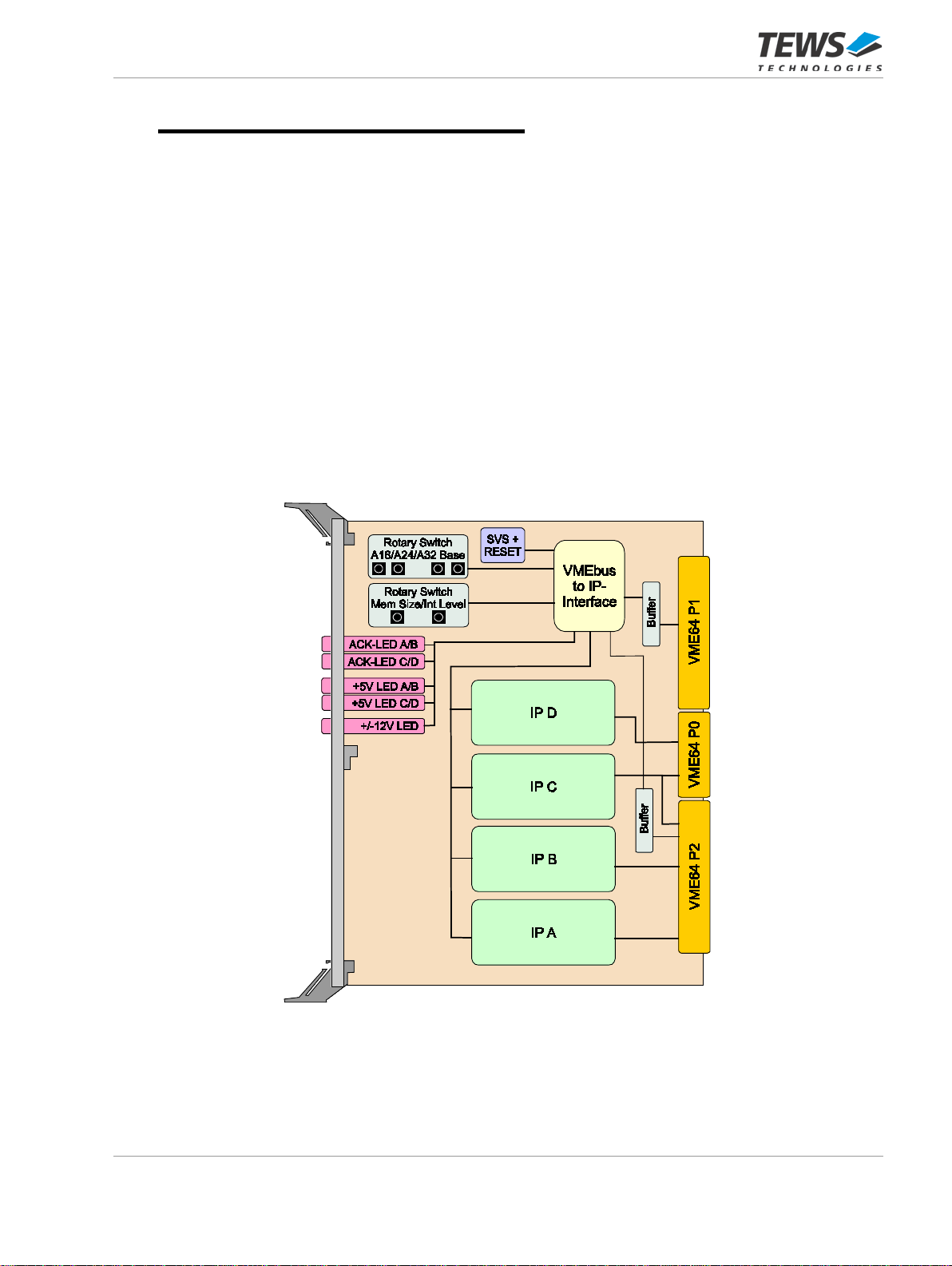
FIGURE 1-1 : BLOCK DIAGRAM TVME220.....................................................................................................6
FIGURE 1-2 : BLOCK DIAGRAM TVME001-TM-10R......................................................................................7
FIGURE 1-3 : BLOCK DIAGRAM TVME002-TM-10R......................................................................................7
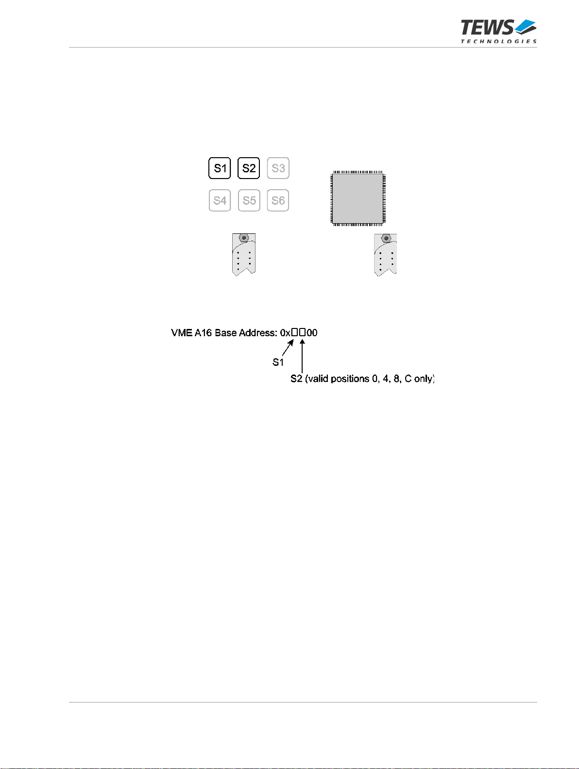
FIGURE 3-1 : ROTARY SWITCH S1 – S6........................................................................................................9
FIGURE 3-3 : VME A16 BASE ADDRESS .....................................................................................................10
FIGURE 3-6 : INTERRUPT MAPPING ...........................................................................................................12
FIGURE 3-8 : VME A24/A32 MEMORY ENABLE AND MEMORY SIZE .......................................................13
FIGURE 3-10: VME A24/A32 BASE ADDRESS..............................................................................................14
FIGURE 5-1 : IP STROBE SIGNAL ................................................................................................................20

TVME220 User Manual Issue 1.1.1 Page 6 of 26
1 Product Description
The TVME220 is a 6U VMEbus carrier for up to 4 single-size or two double-size IndustryPack (IP)
modules. It provides modular, flexible and cost effective I/O solutions for all kinds of applications like
process control, medical systems, telecommunication and traffic control.
The TVME220 uses VME64x-compliant connectors to increase the quantity of rear I/O connections
beyond that of standard VME. All of the 200 I/O lines from the 4 IP slots are available at the VME64x
connectors P0 and P2. The I/O mapping is compliant to the ANSI/VITA 4.1-1996 standard.
Although the rear connectors are VME64x, the electrical interface is standard VME, so that nearly all
CPU products still have full access to the IP modules mounted on the TVME220.
Status indicators for IP access, +5V and +/-12V are provided in the EMI shielded front panel.
A set of 16-position rotary switches allows easy configuration of VME Short I/O and Memory
addresses. Interrupt routing from the IP slots to the VME IRQ’s can be done in two ways:
programmable by software or selection of predefined sets by a rotary switch.
The IP power lines are fuse protected by self healing fuses and RF filtered. The operating temperature
range is -40°C and +85°C.
Figure 1-1 : Block Diagram TVME220

TVME220 User Manual Issue 1.1.1 Page 7 of 26
Two Transition Modules, TVME001-TM-10R and TVME002-TM-10R are available for easy access to
all IP I/O lines.
Figure 1-2 : Block Diagram TVME001-TM-10R
Figure 1-3 : Block Diagram TVME002-TM-10R

TVME220 User Manual Issue 1.1.1 Page 8 of 26
2 Technical Specification
VMEbus Slave Interface VME64 (ANSI/VITA 1-1994) and VME64x (ANSI/VITA 1.1-1997)
compliant slave interface
Short I/O
VME A16, D08/16,
Address Modifier: 29, 2D
Size: 1 Kbytes (256 Bytes / IP)
Standard Memory
VME A24, D08/16,
Address Modifier: 39, 3A, 3D, 3E
Size: programmable from 32 Kbytes to 2 Mbytes per IP
Extended Memory
VME A32, D08/16,
Address Modifier: 09, 0A, 0D, 0E
Size: fixed, 8 Mbytes per IP
Interrupts VME IRQ1-7
IP Interface ANSI/VITA 4-1995 compliant interface to IndustryPack modules
IP Slots
Four single sized or two double sized IP slots with back I/O
Mapping of IP Interrupts to
VMEbus Programmable by software or selection of predefined sets by a rotary
switch
I/O access ANSI/VITA 4.1-1996 compliant mapping of IP I/O lines to VME64x
connectors P0 and P2
DMA
32 MHz
32 Bit
Not supported
Not supported
Not supported
Status LEDs ACK LED for each IP Slot
+5V Power LED for each IP Slot
+12V and –12V Power LED
Protection Self healing fuses and RF-filtering on all IP power lines
Operating Data
Power Requirements
without IP Modules
350mA @ +5V DC
1mA typical@ +12V DC
1mA typical@-12V DC
Additional Power is required by IP modules
Temperature Range
Operating: – 40°C to + 85°C
Storage: – 40°C to + 85°C
MTBF
382000 h
MTBF values shown are based on calculation according to MIL-HDBK-217F and
MIL-HDBK-217F Notice 2; Environment: GB20°C.
The MTBF calculation is based on component FIT rates provided by the
component suppliers. If FIT rates are not available, MIL-HDBK-217F and
MIL-HDBK-217F Notice 2 formulas are used for FIT rate calculation
Weight
310 g
Size
Singe Size 6U Euro Card
Humidity
5 – 95 % non-condensing
Table 2-1 : Technical Specification

TVME220 User Manual Issue 1.1.1 Page 9 of 26
3 Configuration
All required configuration of the TVME220 can be done by setting 6 rotary switches. Position of the
switches is shown below:
Figure 3-1 : Rotary Switch S1 – S6
Step Rotary Switch Function Default Value
1 S1 / S2 VME A16 Base Address 0x6000
2 S3 Interrupt Mapping VIPC6xx compatible
3 S4 VME A24/A32 Memory Enable and
Memory Size Disabled
4 S5 / S6 VME A24/A32 Memory Base Address A24: 0xD00000
A32: 0xD0000000
Table 3-1 : Configuration Steps TVME220

TVME220 User Manual Issue 1.1.1 Page 10 of 26
3.1VME A16 Base Address
The VME A16 Base Address of the TVME220 is set by rotary switch S1 and S2.
Rotary switch S1 configures A[15:12] of the VME A16 Base Address.
Rotary switch S2 configures A[11:10] of the VME A16 Base Address.
Figure 3-2 : VME A16 Base Address
The default value for the VME A16 Base Address is 0x6000 (S1=6, S2=0).
The TVME220 requires an address space of 1 Kbytes within the VME A16 address space. Each of the
four IP slots occupies 256 bytes within this 1 Kbytes VME A16 address space.
The address space for each IP is divided into the following areas: IP I/O space, IP ID space and the IP
IRQ and Control Register.
The IP I/O space has a size of 128 bytes. The size of the IP ID space and the IP IRQ and Control
Register depends on the position of switch S3:
With S3 = “0” to “7”, the IP IRQ and Control Registers of the TVME220 are accessible, and the size of
the IP ID space is 64 bytes. The remaining 64 bytes are occupied by the IP IRQ and Control
Registers. If switch S3 = “8” to “F”, the IP IRQ and Control Registers of the TVME220 are not
accessible, and the corresponding address range is added to the IP ID space, resulting in a size of
128 bytes for the IP ID space with S3 = “8” to “F”. This configuration is necessary for IP modules that
require access to the ID Space above the ID PROM.
See figures below for more details.

TVME220 User Manual Issue 1.1.1 Page 11 of 26
VME A16 Base Address
Description
Default
+ 0x0000 I/O Space IP A 0x6000
+ 0x0080 ID Space IP A 0x6080
+ 0x00C0 IRQ and Control Register IP A 0x60C0
+ 0x0100 I/O Space IP B 0x6100
+ 0x0180 ID Space IP B 0x6180
+ 0x01C0 IRQ and Control Register IP B 0x61C0
+ 0x0200 I/O Space IP C 0x6200
+ 0x0280 ID Space IP C 0x6280
+ 0x02C0 IRQ and Control Register IP C 0x62C0
+ 0x0300 I/O Space IP D 0x6300
+ 0x0380 ID Space IP D 0x6380
+ 0x03C0 IRQ and Control Register IP D 0x63C0
Table 3-2 : VME A16 Address Map (S3 = “0” to “7”)
VME A16 Base Address
Description
Default
+ 0x0000 I/O Space IP A 0x6000
+ 0x0080 ID Space IP A 0x6080
+ 0x0100 I/O Space IP B 0x6100
+ 0x0180 ID Space IP B 0x6180
+ 0x0200 I/O Space IP C 0x6200
+ 0x0280 ID Space IP C 0x6280
+ 0x0300 I/O Space IP D 0x6300
+ 0x0380 ID Space IP D 0x6380
Table 3-3 : VME A16 Address Map (S3 = “8” to “F”)

TVME220 User Manual Issue 1.1.1 Page 12 of 26
3.2Interrupts
Each IndustryPack can generate interrupts on two interrupt request lines (INT0 and INT1). The
VMEbus offers seven interrupt request levels. IRQ7 has the highest priority, IRQ1 has the lowest
priority.
IP interrupt requests can be mapped to any of the 7 VME interrupt request levels. Interrupt routing
from the IP slots to the VME IRQs can be done by selection of predefined sets with a rotary switch or
programmable by software if S3 is in the range of “0” to “7”.
For more information about fully programmable interrupt mapping please refer to chapter “IP IRQ and
Control Register”.
Rotary switch S3 can be used to select predefined sets of mapping of the eight IP interrupt requests
(two requests per IP slot) to the seven VME interrupt request levels. The mapping selected with S3 =
“0” to “7” is mirrored at S3 = “8” to “F”. The difference is that access to the IP IRQ and Control
Registers of the TVME220 is only possible in switch position S3 = “0” to “7”. See Chapter “VME A16
Base Address” and Chapter “IP IRQ and Control Register” for more details.
Figure 3-3 : Interrupt Mapping
S3 = 0 1 2 3 4 5…7 8* 9* A* B* C* D*…F*
IPA, Int0 - 1 4 6 1 reserved - 1 4 6 1 reserved
IPA, Int1 - 2 5 4 1 reserved - 2 5 4 1 reserved
IPB, Int0 - 3 2 3 2 reserved - 3 2 3 2 reserved
IPB, Int1 - 4 1 1 2 reserved - 4 1 1 2 reserved
IPC, Int0 - 5 4 6 3 reserved - 5 4 6 3 reserved
IPC, Int1 - 6 5 4 3 reserved - 6 5 4 3 reserved
IPD, Int0 - 7 2 3 4 reserved - 7 2 3 4 reserved
IPD, Int1 - - 1 1 4 reserved - - 1 1 4 reserved
“-” = No VME IRQ level mapped to IP INTx * no access to the IP IRQ and Control registers of the
TVME220 , see Chapter 4 and Chapter 3.1 for more
details.
Table 3-4 : VME Interrupt Mapping by S3
S3 = “1”, “9” corresponds to the VME Interrupt Mapping of the VIPC6xx
S3 = “2”, “A” corresponds to the VME Interrupt Mapping of the VIPC610-01 (equal to two VIPC310)
S3 = “3”, “B” corresponds to the VME Interrupt Mapping of another version of the VIPC310
The default value for S3 is “1”.

TVME220 User Manual Issue 1.1.1 Page 13 of 26
3.3VME A24/A32 Memory Enable and Memory Size
If VME memory space is not required, switch S4 to “0” (VME A24/A32 memory disabled).
Figure 3-4 : VME A24/A32 Memory Enable and Memory Size
IndustryPack memory is mapped into the VME A24 or VME A32 memory space.
In VME A24 memory space, the memory size can be configured from 32 Kbytes to 2 Mbytes memory
per IP slot.
In VME A32 memory space, the memory size is fixed 8 Mbytes per IP slot.
Rotary switch S4 is used to enable/disable VME A24/A32 memory and to select the required VME
memory size. Default setting of S4 is “0”, which signifies VME A24/A32 memory is disabled.
Positions “1” to “7” of S4 represent several memory spaces in VME A24, and with S4 = “F”, each IP
has an 8 Mbytes memory space in VME A32 address space.
The Memory Spaces for all IPs have the same size. If i.e. one IP requires 128 Kbytes of memory,
one IP requires 64 Kbytes of memory and 2 IP require no memory, then S4 must be set to “3”,
which selects a VME A24 memory size of 512 Kbytes, 128 Kbytes memory for each IP.
Value of S4:
VME Memory Size:
0x0 VME A24/A32 memory disabled
0x1
A24
128 Kbytes
32 Kbytes / IP
0x2 A24 256 Kbytes 64 Kbytes / IP
0x3
A24
512 Kbytes
128 Kbytes / IP
0x4
A24
1 Mbytes
256 Kbytes / IP
0x5 A24 2 Mbytes 512 Kbytes / IP
0x6
A24
4 Mbytes
1 Mbytes / IP
0x7 A24 8 Mbytes 2 Mbytes / IP
0x8 – 0xE
reserved
0xF A32 32 Mbytes 8 Mbytes / IP Slot
Table 3-5 : VME Memory Size by S4

TVME220 User Manual Issue 1.1.1 Page 14 of 26
3.4VME A24/A32 Base Address
The memory space of IndustryPacks is mapped in the VME A24 or VME A32 space.
The memory base address for VME A24 or VME A32 is both set with the switches S5 and S6.
Figure 3-5: VME A24/A32 Base Address
If memory space is located in VME A24, S5 represents A[23:20], and S6 represents A[19:16].
In VME A32, S5 represents [A31:28] and S6 represents A[27:24].
The memory base address of the TVME220 must be set on a boundary, equal to the memory
size, as selected by S4! See figure below for details.
The default value for VME A24 base address is 0xD00000 (S5=D, S6=0).
The default value for VME A32 base address is 0xD0000000 (S5=D, S6=0).

TVME220 User Manual Issue 1.1.1 Page 15 of 26
TVME220
VME A24/A32 Size
IP Memory
Size
IP Slot
IP Memory Location:
Mem. Base Address +
VMEbus Address
Boundary
A24 128 Kbytes
32 Kbytes
32 Kbytes
32 Kbytes
32 Kbytes
A
B
C
D
0x000000
0x008000
0x010000
0x018000
multiple of 0x020000
A24 256 Kbytes
64 Kbytes
64 Kbytes
64 Kbytes
64 Kbytes
A
B
C
D
0x000000
0x010000
0x020000
0x030000
multiple of 0x040000
A24 512 Kbytes
128 Kbytes
128 Kbytes
128 Kbytes
128 Kbytes
A
B
C
D
0x000000
0x020000
0x040000
0x060000
multiple of 0x080000
A24 1 Mbytes
256 Kbytes
256 Kbytes
256 Kbytes
256 Kbytes
A
B
C
D
0x000000
0x040000
0x080000
0x0C0000
multiple of 0x100000
A24 2 Mbytes
512 Kbytes
512 Kbytes
512 Kbytes
512 Kbytes
A
B
C
D
0x000000
0x080000
0x100000
0x180000
multiple of 0x200000
A24 4 Mbytes
1 Mbytes
1 Mbytes
1 Mbytes
1 Mbytes
A
B
C
D
0x000000
0x100000
0x200000
0x300000
multiple of 0x400000
A24 8 Mbytes
2 Mbytes
2 Mbytes
2 Mbytes
2 Mbytes
A
B
C
D
0x000000
0x200000
0x400000
0x600000
multiple of 0x800000
A32 32 Mbytes
8 Mbytes
8 Mbytes
8 Mbytes
8 Mbytes
A
B
C
D
0x00000000
0x00800000
0x01000000
0x01800000
multiple of 0x02000000
Table 3-6 : VME A24/A32 Address Map

TVME220 User Manual Issue 1.1.1 Page 16 of 26
4 IP IRQ and Control Register
If switch S3 is in the range of “0” to “7”, the TVME220 provides a set of two registers for each IP: The
IP IRQ Configuration Register and the IP Control Register.
Setting switch S3 to a value of “8” to “F” disables the IP IRQ Register and the IP Control Register. The
address range of the IP IRQ and Control Register from “VME A16 Base Address” + “IP Offset” + 0xC0
to 0xFF is then mapped to the ID Space of the corresponding IP module, enlarging the ID Space of
each IP module from 64 bytes to 128 bytes.
4.1IP IRQ Configuration Register
Switch S3 must be in the range of “0” to “7” to access the IP IRQ Configuration Register. The register
is divided in 2 equal parts, one for each interrupt. The bits[0, 4] are the LSBs, and the bits[2, 6] are the
MSBs of the programmed IRQ level.
IPA IRQ Configuration Register VME A16 Base Address + 0x00C1
Bit Symbol Description Access Reset Value
7
6 IPA, INT1 VME IRQ Level
000 = interrupt is disabled
[6:4] 001 to 111 = VMEbus IRQ-levels IRQ1 to IRQ7
R/W Depends on
S3 jumper
setting
5 R/W
4 R/W
3 R/W
2 IPA, INT0 VME IRQ Level
000 = interrupt is disabled
[2:0] 001 to 111 = VMEbus IRQ-levels IRQ1 to IRQ7
R/W Depends on
S3 jumper
setting
1 R/W
0 R/W
IPB IRQ Configuration Register VME A16 Base Address + 0x01C1
Bit Symbol Description Access Reset Value
7
6 IPB, INT1 VME IRQ Level
000 = interrupt is disabled
[6:4] 001 to 111 = VMEbus IRQ-levels IRQ1 to IRQ7
R/W Depends on
S3 jumper
setting
5 R/W
4 R/W
3 R/W
2 IPB, INT0 VME IRQ Level
000 = interrupt is disabled
[2:0] 001 to 111 = VMEbus IRQ-levels IRQ1 to IRQ7
R/W Depends on
S3 jumper
setting
1 R/W
0 R/W
Table 4-1 : IP IRQ Configuration Registers (IP A / IP B)

TVME220 User Manual Issue 1.1.1 Page 17 of 26
IPC IRQ Configuration Register VME A16 Base Address + 0x02C1
Bit
Symbol
Description
Access
Reset Value
7
6 IPC, INT1 VME IRQ Level
000 = interrupt is disabled
[6:4] 001 to 111 = VMEbus IRQ-levels IRQ1 to IRQ7
R/W Depends on
S3 jumper
setting
5 R/W
4 R/W
3 R/W
2 IPC, INT0 VME IRQ Level
000 = interrupt is disabled
[2:0] 001 to 111 = VMEbus IRQ-levels IRQ1 to IRQ7
R/W Depends on
S3 jumper
setting
1 R/W
0 R/W
IPD IRQ Configuration Register VME A16 Base Address + 0x03C1
Bit Symbol Description Access Reset Value
7
6 IPD, INT1 VME IRQ Level
000 = interrupt is disabled
[6:4] 001 to 111 = VMEbus IRQ-levels IRQ1 to IRQ7
R/W Depends on
S3 jumper
setting
5 R/W
4 R/W
3 R/W
2 IPD, INT0 VME IRQ Level
000 = interrupt is disabled
[2:0] 001 to 111 = VMEbus IRQ-levels IRQ1 to IRQ7
R/W Depends on
S3 jumper
setting
1 R/W
0 R/W
Table 4-2 : IP IRQ Configuration Registers (IP C / IP D)

TVME220 User Manual Issue 1.1.1 Page 18 of 26
4.2IP Control Register
Four IP Control Registers are located in the VMEbus A16 space. Switch S3 must be in the range of “0”
to “7” to access the IP Control Register.
IPA Control Register VME A16 Base Address + 0x00C3
Bit
Symbol
Description
Access
Reset Value
7 IP A, Reset 1 = reset is initiated
Remains ‘1’, until the IP reset has been completed
and is then set to ‘0’ by the on board logic. It can
be read to verify the status of the reset.
R/W 0
6 reserved
Carry random information
R undefined
5 reserved R undefined
4 reserved R undefined
3 reserved R undefined
2 IP A, Error 1 = error signal is active R 0
1
IP A, INT1
Interrupt status
1 = indicates a pending interrupt request
R
0
0 IP A, INT0 R 0
IPB Control Register VME A16 Base Address + 0x01C3
Bit
Symbol
Description
Access
Reset Value
7 IP B, Reset 1 = reset is initiated
Remains ‘1’, until the IP reset has been completed
and is then set to ‘0’ by the on board logic. It can
be read to verify the status of the reset.
R/W 0
6
reserved
Carry random information
R
undefined
5 reserved R undefined
4 reserved R undefined
3 reserved R undefined
2 IP B, Error 1 = error signal is active R 0
1 IP B, INT1 Interrupt status
1 = indicates a pending interrupt request R 0
0 IP B, INT0 R 0
Table 4-3 : IP Control Registers (IP A / IP B)

TVME220 User Manual Issue 1.1.1 Page 19 of 26
IPC Control Register VME A16 Base Address + 0x02C3
Bit
Symbol
Description
Access
Reset Value
7 IP C, Reset 1 = reset is initiated
Remains ‘1’, until the IP reset has been completed
and is then set to ‘0’ by the on board logic. It can
be read to verify the status of the reset.
R/W 0
6
reserved
Carry random information
R
undefined
5 reserved R undefined
4 reserved R undefined
3 reserved R undefined
2 IP C, Error 1 = error signal is active R 0
1 IP C, INT1 Interrupt status
1 = indicates a pending interrupt request R 0
0 IP C, INT0 R 0
IPD Control Register VME A16 Base Address + 0x03C3
Bit Symbol Description Access Reset Value
7 IP D, Reset 1 = reset is initiated
Remains ‘1’, until the IP reset has been completed
and is then set to ‘0’ by the on board logic. It can
be read to verify the status of the reset.
R/W 0
6 reserved
Carry random information
R undefined
5 reserved R undefined
4 reserved R undefined
3
reserved
R
undefined
2 IP D, Error 1 = error signal is active R 0
1 IP D, INT1 Interrupt status
1 = indicates a pending interrupt request R 0
0 IP D, INT0 R 0
Table 4-4 : IP Control Registers (IP C / IP D)

TVME220 User Manual Issue 1.1.1 Page 20 of 26
5 IP Strobe Signal
The IP strobe signal is an uncommitted line of the IP logic interface, which may be used as an optional
input to or output from an IP module. It is reserved for a digital strobe or clock signal related to the
functionality of the IP.
Strobe signals of each IP slots are accessible on the TVME220 via a 4 pin jumper field.
Figure 5-1 : IP Strobe Signal
This manual suits for next models
2
Table of contents
Other Tews Technologies Motherboard manuals