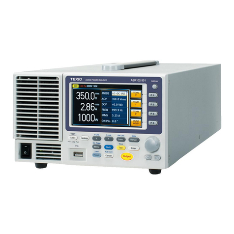
TEXIO ASR Series Owner's manual

Front cover
PROGRAMMINGMANUAL
B71-0499-01
AC/DC POWER SOURCE
ASR SERIES

■ About a trademark, a registered trademark
A company name and the brand name mentioned in this
instruction manual are the trademark or the registered
trademark of each company or group in each country and region.
■ About this instruction manual
When copying the part or all of contents of this instruction
manual, seek the copyright holder.
In addition, the specifications of the product and the contents of
this instruction manual are subject to change without notice for
improvement. Please check to our website for the latest version.
■ About firmware version
This programming manual is required firmware version 1.03 or
higher.

3
Table of Contents
1. REMOTE CONTROL........................................ 1
1-1. Interface Configuration ....................................1
1-1-1. Configure Ethernet Connection ...........................................................1
1-1-2. Web Server Remote Control Function Check......................................2
1-1-3. Socket Server Function Check............................................................4
1-2. USB Interface ..................................................8
1-2-1. USB Remote Interface ........................................................................8
1-2-2. USB Remote Control Function Check .................................................10
1-3. RS-232C Interface(G Type)............................ 11
1-3-1. RS-232C Remote Interface.................................................................11
1-3-2. RS-232C Remote Control Function Check ..........................................13
1-3-3. Using Realterm to Establish a Remote Connection .............................14
1-4. GP-IB Interface(G type) .................................17
1-4-1. GPIB Remote Interface .......................................................................17
1-4-2. GPIB Function Check..........................................................................18
2. Command Syntax......................................... 21
3. Command List .............................................. 25
3-1. Common Commands...........................................................................25
3-1-1. *CLS...................................................................................................25
3-1-2. *IDN...................................................................................................25
3-1-3. *OPC..................................................................................................25
3-1-4. *RCL...................................................................................................26
3-1-5. *RST...................................................................................................26
3-1-6. *SAV...................................................................................................26
3-1-7. *WAI...................................................................................................27
3-2. Trace/Data Commands................................. 27
3-2-1. :DATA|TRACe:SEQuence:CLEar .......................................................27
3-2-2. :DATA|TRACe:SEQuence:RECall ......................................................27
3-2-3. :DATA|TRACe:SEQuence:STORe......................................................28
3-2-4. :DATA|TRACe:SIMulation:CLEar........................................................28
3-2-5. :DATA|TRACe:SIMulation:RECall.......................................................28
3-2-6. :DATA|TRACe:SIMulation:STORe......................................................29
3-2-7. :DATA|TRACe:WAVe:CLEar ..............................................................29
3-2-8. :DATA|TRACe:WAVe[:DATA].............................................................29
3-3. Measure Commands....................................31
3-3-1. :MEASure[:SCALar]:CURRent:CFACtor.............................................31
3-3-2. :MEASure[:SCALar]:CURRent:HIGH..................................................31
3-3-3. :MEASure[:SCALar]:CURRent:LOW...................................................31
3-3-4. :MEASure[:SCALar]:CURRent:PEAK:CLEar.......................................31
3-3-5. :MEASure[:SCALar]:CURRent:PEAK:HOLD.......................................32
3-3-6. :MEASure[:SCALar]:CURRent[:RMS].................................................32
3-3-7. :MEASure[:SCALar]:CURRent:AVERage ...........................................32
3-3-8. :MEASure[:SCALar]:CURRent:HARMonic[:RMS] ...............................32

3-3-9. :MEASure[:SCALar]:CURRent:HARMonic:RATio...............................33
3-3-10.:MEASure[:SCALar]:FREQuency .......................................................33
3-3-11.:MEASure[:SCALar]:POWer[:AC]:APParent.......................................33
3-3-12.:MEASure[:SCALar]:POWer[:AC]:PFACtor.........................................33
3-3-13.:MEASure[:SCALar]:POWer[:AC]:REACtive.......................................34
3-3-14.:MEASure[:SCALar]:POWer[:AC][:REAL]...........................................34
3-3-15.:MEASure[:SCALar]:VOLTage[:RMS].................................................34
3-3-16.:MEASure[:SCALar]:VOLTage:AVERage...........................................34
3-3-17 :MEASure[:SCALar]:VOLTage:HIGH ................................................34
3-3-18.:MEASure[:SCALar]:VOLTage:LOW...................................................35
3-3-19.:MEASure[:SCALar]: VOLTage:HARMonic[:RMS]..............................35
3-3-20.:MEASure[:SCALar]: VOLTage:HARMonic:RATio..............................35
3-3-21.:MEASure:CONFigure:SENSing.........................................................36
3-4. Memory Commands ..................................... 36
3-4-1. :MEMory:RCL.....................................................................................36
3-4-2. :MEMory:SAV.....................................................................................37
3-5. Output Commands ....................................... 37
3-5-1. :OUTPut[:STATe]...............................................................................37
3-5-2. :OUTPut:PON ....................................................................................37
3-5-3. :OUTPut:PROTection:CLEar..............................................................38
3-5-4. :OUTPut:RELay..................................................................................38
3-6. System Function Commands........................ 38
3-6-1. :SYSTem:BEEPer:STATe ..................................................................38
3-6-2. :SYSTem:COMMunicate:GPIB[:SELF]:ADDRess...............................39
3-6-3. :SYSTem:COMMunicate:LAN:DHCP..................................................39
3-6-4. :SYSTem:COMMunicate:LAN:DNS....................................................40
3-6-5. :SYSTem:COMMunicate:LAN:GATEway............................................40
3-6-6. :SYSTem:COMMunicate:LAN:IPADdress...........................................40
3-6-7. :SYSTem:COMMunicate:LAN:MAC....................................................41
3-6-8. :SYSTem:COMMunicate:LAN:SMASk................................................41
3-6-9. :SYSTem:COMMunicate:RLSTate .....................................................41
3-6-10.:SYSTem:COMMunicate:SERial[:RECeive]:TRANsmit:BAUD............42
3-6-11.:SYSTem:COMMunicate:SERial[:RECeive]:TRANsmit:BITS..............42
3-6-12.:SYSTem:COMMunicate:SERial[:RECeive]:TRANsmit:PARity...........43
3-6-13.:SYSTem:COMMunicate:SERial[:RECeive]:TRANsmit:SBITs ............44
3-6-14.:SYSTem:COMMunicate:TCPip:CONTrol...........................................44
3-6-15.:SYSTem:COMMunicate:USB:FRONt:STATe ....................................45
3-6-16.:SYSTem:COMMunicate:USB:REAR:MODE......................................45
3-6-17.:SYSTem:COMMunicate:USB:REAR:STATe .....................................46
3-6-18.:SYSTem:CONFigure[:MODE] ...........................................................46
3-6-19.:SYSTem:CONFigure:EXTio[:STATe].................................................46
3-6-20.:SYSTem:ERRor................................................................................47
3-6-21.:SYSTem:ERRor:ENABle...................................................................47
3-6-22.:SYSTem:HOLD:STATe.....................................................................47
3-6-23.:SYSTem:IPKHold:TIME ....................................................................47
3-6-24.:SYSTem:KLOCk ...............................................................................48
3-6-25.:SYSTem:REBoot...............................................................................48
3-6-26.:SYSTem:SLEW:MODE .....................................................................48
3-7. Source Commands....................................... 49
3-7-1. [:SOURce]:CURRent:LIMit:PEAK:HIGH .............................................49
3-7-2. [:SOURce]:CURRent:LIMit:PEAK:LOW..............................................49
3-7-3. [:SOURce]:CURRent:LIMit:RMS[:AMPLitude] ....................................50

3-7-4. [:SOURce]:CURRent:LIMit:PEAK:MODE............................................50
3-7-5. [:SOURce]:CURRent:LIMit:RMS:MODE .............................................51
3-7-6. [:SOURce]:FREQuency:LIMit:HIGH....................................................51
3-7-7. [:SOURce]:FREQuency:LIMit:LOW.....................................................52
3-7-8. [:SOURce]:FREQuency[:IMMediate]...................................................52
3-7-9. [:SOURce]:FUNCtion[:SHAPe][:IMMediate]........................................53
3-7-10.[:SOURce]:FUNCtion:THD:FORMat ...................................................54
3-7-11.[:SOURce]:MODE...............................................................................54
3-7-12.[:SOURce]:PHASe:STARt:STATe.......................................................55
3-7-13.[:SOURce]:PHASe:STOP:STATe .......................................................55
3-7-14.[:SOURce]:PHASe:STARt[:IMMediate]...............................................56
3-7-15.[:SOURce]:PHASe:STOP[:IMMediate]................................................56
3-7-16.[:SOURce]:READ................................................................................57
3-7-17.[:SOURce]:VOLTage:RANGe.............................................................57
3-7-18.[:SOURce]:VOLTage:LIMit:RMS.........................................................58
3-7-19.[:SOURce]:VOLTage:LIMit:HIGH........................................................58
3-7-20.[:SOURce]:VOLTage:LIMit:LOW.........................................................59
3-7-21.[:SOURce]:VOLTage[:LEVel][:IMMediate][:AMPLitude].......................59
3-7-22.[:SOURce]:VOLTage[:LEVel][:IMMediate]:OFFSet .............................60
3-8. Sequence Commands ..................................61
3-8-1. [:SOURce]:SEQuence:CPARameter...................................................61
3-8-2. [:SOURce]:SEQuence:CSTep ............................................................62
3-8-3. [:SOURce]:SEQuence:SPARameter...................................................62
3-8-4. [:SOURce]:SEQuence:STEP..............................................................63
3-8-5. :TRIGger:SEQuence:SELected:EXECute...........................................64
3-9. Simulate Commands ....................................64
3-9-1. [:SOURce]:SIMulation:ABNormal:CODE.............................................64
3-9-2. [:SOURce]:SIMulation:ABNormal:FREQuency....................................65
3-9-3. [:SOURce]:SIMulation:ABNormal:PHASe:STARt:ENABle...................65
3-9-4. [:SOURce]:SIMulation:ABNormal:PHASe:STARt[:IMMediate].............66
3-9-5. [:SOURce]:SIMulation:ABNormal:PHASe:STOP:ENABle ...................66
3-9-6. [:SOURce]:SIMulation:ABNormal:PHASe:STOP[:IMMediate] .............67
3-9-7. [:SOURce]:SIMulation:ABNormal:TIME ..............................................67
3-9-8. [:SOURce]:SIMulation:ABNormal:VOLTage........................................68
3-9-9. [:SOURce]:SIMulation:CSTep.............................................................68
3-9-10.[:SOURce]:SIMulation:INITial:CODE ..................................................68
3-9-11.[:SOURce]:SIMulation:INITial:FREQuency .........................................69
3-9-12.[:SOURce]:SIMulation:INITial:PHASe:STARt:ENABle.........................69
3-9-13.[:SOURce]:SIMulation:INITial:PHASe:STARt[:IMMediate] ..................70
3-9-14.[:SOURce]:SIMulation:INITial:PHASe:STOP:ENABle .........................70
3-9-15.[:SOURce]:SIMulation:INITial:PHASe:STOP[:IMMediate] ...................71
3-9-16.[:SOURce]:SIMulation:INITial:VOLTage..............................................71
3-9-17.[:SOURce]:SIMulation:NORMal<1|2>:CODE......................................72
3-9-18.[:SOURce]:SIMulation:NORMal 1:FREQuency...................................72
3-9-19.[:SOURce]:SIMulation:NORMal<1|2>:PHASe:STARt:ENABle ............73
3-9-20.[:SOURce]:SIMulation:NORMal<1|2>:PHASe:STARt[:IMMediate]......73
3-9-21.[:SOURce]:SIMulation:NORMal<1|2>:PHASe:STOP:ENABle.............74
3-9-22.[:SOURce]:SIMulation:NORMal<1|2>:PHASe:STOP[:IMMediate].......74
3-9-23.[:SOURce]:SIMulation:NORMal<1|2>:TIME........................................75
3-9-24.[:SOURce]:SIMulation:NORMal1:VOLTage ........................................75
3-9-25.[:SOURce]:SIMulation:REPeat:COUNt ...............................................76
3-9-26.[:SOURce]:SIMulation:REPeat:ENABle ..............................................76
3-9-27.[:SOURce]:SIMulation:TRANsition<1|2>:TIME....................................76

3-9-28.[:SOURce]:SIMulation:TRANsition<1|2>:CODE..................................77
3-9-29.:TRIGger:SIMulation:SELected:EXECute...........................................77
3-10. Input Subsystem Command........................78
3-10-1.:INPut:GAIN .......................................................................................78
3-10-2.:INPut:SYNC:SOURce .......................................................................78
3-11. Display Command ...................................... 79
3-11-1.:DISPlay[:WINDow]:DESign:MODE....................................................79
3-11-2.:DISPlay[:WINDow]:MEASure:SOURce<1|2|3>..................................79
4. Error List ..................................................... 80
4-1. Command Errors.......................................... 80
4-2. Execution Errors ..........................................84
4-3. Device Specific Errors..................................86
4-4. Query Errors................................................ 87
5. APPENDIX ................................................... 88
5-1. Factory Default Settings.............................. 88

1
1. REMOTE CONTROL
This chapter describes basic configuration of IEEE488.2
based remote control.
1-1.Interface Configuration
1-1-1. Configure Ethernet Connection
The Ethernet interface can be configured for a number of different
applications. Ethernet can be configured for basic remote control or
monitoring using a web server or it can be configured as a socket
server.
The ASR supports both DHCP connections so the instrument can
be automatically connected to an existing network or alternatively,
network settings can be manually configured.
Ethernet
Parameters
MAC Address
(display only)
DHCP
IPAddress
Subnet mask
Gateway
DNS address
DNS Server
Socket port fixed at 2268
Ethernet
Configuration
1. Connect a LAN cable from the PC
to the Ethernet port on the rear
panel.
LAN
2. Press the Menu key. The Menu
setting will appear on the display.
3. Use the scroll wheel to go to item 3, LAN and
press Enter.
4. If the LAN cable is installed correctly a
connection is active, the Connection Status will
show Online.

2
5. To automatically have the network assign an IP
address, set DHCP to ON. Otherwise set
DHCP to OFF to manually set the Ethernet
settings.
DHCP
ON, OFF
6. If DHCP was set to OFF, configure the
remaining LAN parameters.
IPAddress
Subnet Mask
Gateway
DNS Server
Socket Port
LAN configuration - 1
LAN configuration - 2
Exit
7. Press Exit[F4] to exit from the
LAN settings.
Note
If connecting to an existing network, check the
settings with your administrator.

3
1-1-2. Web Server Remote Control Function Check
Functionality
Check
Enter the IP address of the power supply (for
example: http:// XXX.XXX.XXX.XXX) in a web
browser after the instrument has been
configured for LAN (page 1).
The web interface allows you to:
View the system and information and the
network configuration.
View the analog control pinout.
View the dimensions of the unit.
View the operating area
Example:

4
1-1-3. Socket Server Function Check
Background
To test the socket server functionality, National
Instruments Measurement and Automation
Explorer can be used. This program is available
on the NI website, www.ni.com., via a search
for the VISA Run-time Engine page, or
“downloads” at the following URL,
http://www.ni.com/visa/
Requirements
Operating System: Windows XP, 7, 8, 10
Functionality
Check
1. Start the NI Measurement and Automation
Explorer (MAX) program. Using Windows,
press:
Start>All Programs>NI MAX
2. From the Configuration panel access;
My System>Devices and Interfaces>Network
Devices
3. Press Add New Network Device>Visa TCP/IP
Resource…

5
2
3
4. Select Manual Entry of Raw Socket from the
popup window.
4
5. Enter the IP address and the port number of
the ASR. The port number is fixed at 2268.
6. Double click the Validate button and press
Next.

6
5
6
7. Next configure the Alias (name) of the ASR
connection. In this example the Alias is: ASR
8. Click finish.
7
8
9. The IP address of the power supply will now
appear under Network Devices in the
configuration panel. Select this icon now.
10.Press Open VISA Test Panel.

7
9
10
11.Click the Configuration Icon. Under the IO
Settings tab check Enable Termination
Character. The termination character should
be set as Line Feed -\n.
11
12.Click the Input/Output icon. Under the Basic
I/O tab, make sure *IDN?\n is entered in the
Select or Enter Command drop box.
13.Click Query.
The ASR will return the machine identification
string into the buffer area:
TEXIO, ASRXXX-XXX, XXXXXXXXX,
XX.XX.XX.XXXX-X

8
13
12
1-2.USB Interface
1-2-1. USB Remote Interface
USB
Configuration
PC side
connector
Type A, host
ASR side
connector
Rear panel Type B, slave
Speed
1.1/2.0 (full speed/auto speed)
USB Class
CDC (communications device
class)
Steps
1. Connect the Type A-Type B USB
cable from the PC to the rear
panel USB B port.
2. Press the Menu key. The Menu
setting will appear on the display.
3. Use the scroll wheel to go to item 4, USB
Device and press Enter.
4. Go to the Speed setting and set the USB
speed.

9
Speed
Full(default), Auto
5. If the connection is successful Connection
Status will change from Offline to Online.
USB Device Configuration
Exit
6. Press Exit[F4] to exit from the rear
panel USB settings.

10
1-2-2. USB Remote Control Function Check
Functionality
Check
Invoke a terminal application such as Realterm.
ASR will appear as a COM port on the PC.
To check the COM settings in Windows, see the
Device Manager. For example, in Win7 go to
the Control panel → System → Hardware tab.
Note
If you are not familiar with using a terminal
application to send/receive remote commands
via a USB connection, please see page 14 for
more information.
Run this query command via the terminal after
the instrument has been configured for
USB remote control (page 8).
*IDN?
This should return the Manufacturer, Model
number, Serial number, and Software version in
the following format.
TEXIO, ASRXXX-XXX, XXXXXXXXX,
XX.XX.XX.XXXX-X
Manufacturer: TEXIO
Model number : ASRXXX-XXX
Serial number : XXXXXXXXX
Software version : XX.XX.XX.XXXX-X

11
1-3.RS-232C Interface(G Type)
1-3-1. RS-232C Remote Interface
RS-232C
Configuration
Connector
BD-9, male
Parameters
Baud rate, data bits, parity, stop
bits.
Pin Assignment
12345
6789
2: RxD (Receive data)
3: TxD (Transmit data)
5: GND
4, 6 ~ 9: No connection
Pin Connection
Use a Null Modem connection (RS-232C cable)
as shown in the diagram below.
ASR PC
RxDPin2 RxD Pin2
GNDPin5 GND Pin5
TxD Pin3
TxDPin3
Steps
1. Connect the RS-232C cable from
the PC to the rear panel RS-232
port.
2. Press the Menu key. The Menu
setting will appear on the display.
3. Use the scroll wheel to go to item 5, RS232C
and press Enter.
4. Set the RS232C relative settings.
Baud rate
1200, 2400, 4800,
9600(default), 19200,
38400, 57600, 115200,

12
Data bits
7 bits, 8 bits(default)
Parity
None(default), Odd, Even
Stop bits
1 bit(default), 2 bits
RS232C Configuration
Exit
5. Press Exit[F4] to exit from the
RS232C settings.

13
1-3-2. RS-232C Remote Control Function Check
Functionality
Check
Invoke a terminal application such as Realterm.
For RS-232C, set the COM port, baud rate,
stop bit, data bit and parity accordingly.
To check the COM settings in Windows, see the
Device Manager. For example, in Win7 go to
the Control panel → System → Hardware tab.
Note
If you are not familiar with using a terminal
application to send/receive remote commands
from the serial port, please see page 14 for
more information.
Run this query command via the terminal after
the instrument has been configured for
RS-232C remote control (page 11).
*IDN?
This should return the Manufacturer, Model
number, Serial number, and Software version in
the following format.
TEXIO, ASRXXX-XXX, XXXXXXXXX,
XX.XX.XX.XXXX-X
Manufacturer: TEXIO
Model number : ASRXXX-XXX
Serial number : XXXXXXXXX
Software version : XX.XX.XX.XXXX-X

14
1-3-3. Using Realterm to Establish a Remote Connection
Background
Realterm is a terminal program that can be
used to communicate with a device attached to
the serial port of a PC or via an emulated serial
port via USB.
The following instructions apply to version
2.0.0.70. Even though Realterm is used as an
example to establish a remote connection, any
terminal program can be used that has similar
functionality.
Note
Realterm can be downloaded on
Sourceforge.net free of charge.
For more information please see
http://realterm.sourceforge.net/
Operation
1. Download Realterm and install according to
the instructions on the Realterm website.
2. Connect the ASR via USB (page 8) or via RS-
232 (page 11).
3. If using RS-232, make note of the configured
baud rate, stop bits and parity.
4. Go to the Windows device manager and find
the COM port number for the connection.
For example, go to the Start menu > Control
Panel > Device Manager.
Double click the Ports icon to reveal the
connected serial port devices and the COM port
for the each connected device.
If using USB, the baud rate, stop bit and parity
Other manuals for ASR Series
2
This manual suits for next models
4
Table of contents
Other TEXIO Portable Generator manuals