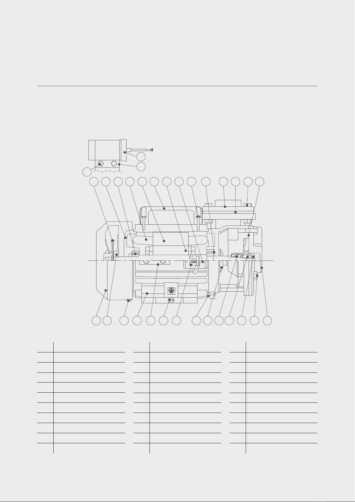
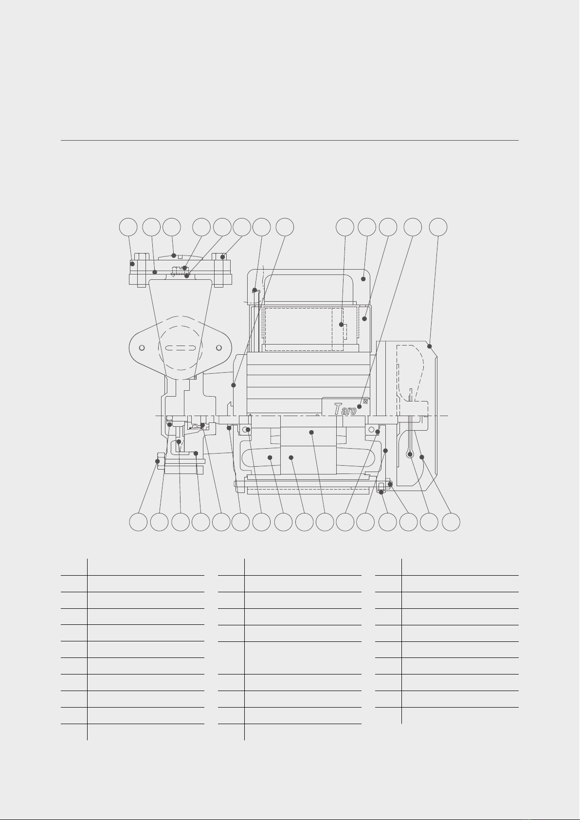
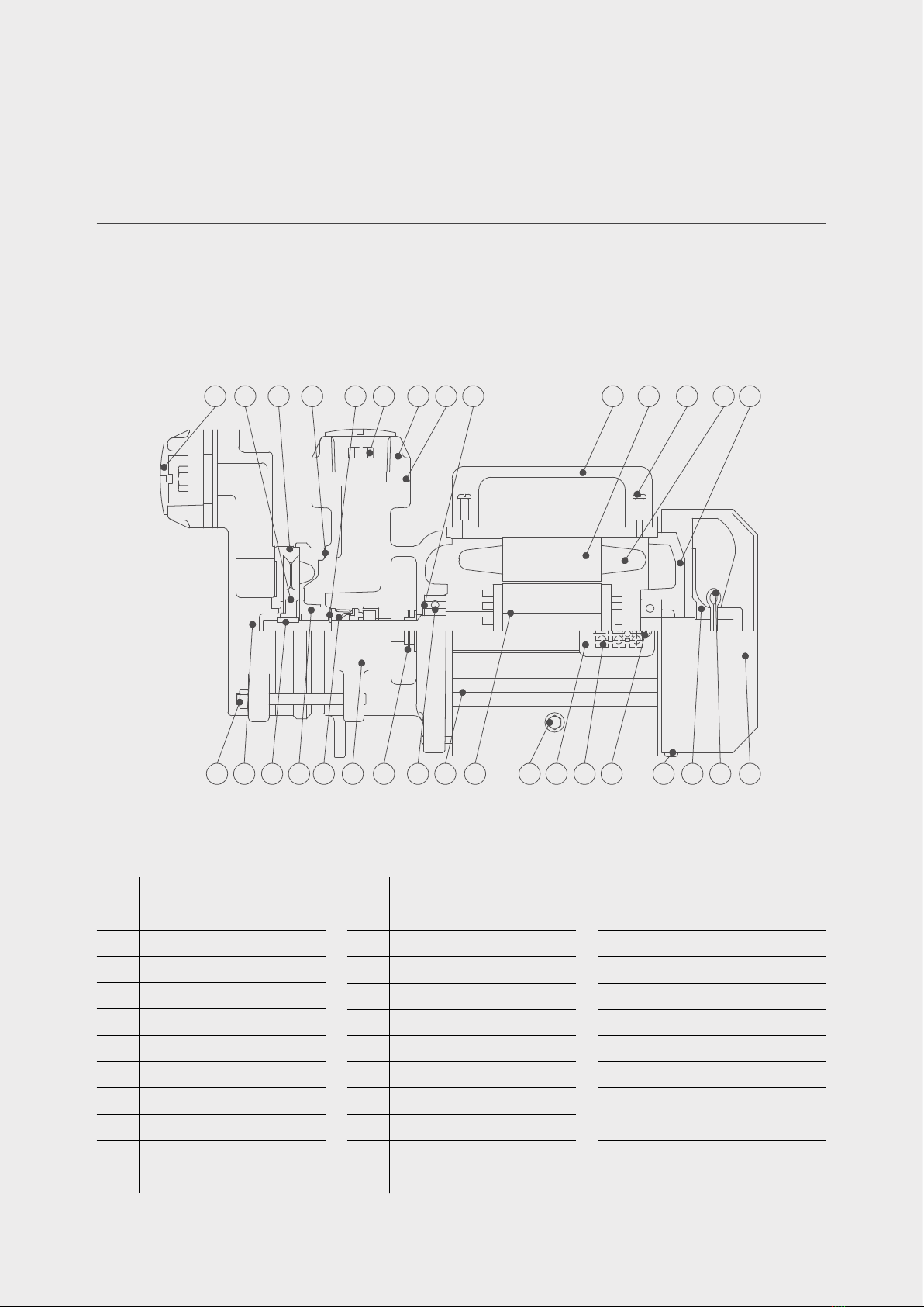
Texmo Industries Taro Single Phase Domestic Monoblock Parts list manual

Single Phase
Domestic
and Mini
Monoblocks
Instruction &
Operating Manual
OMMM001A 2020.01

OMMM001A 22020.01

Table of Contents
1. Introduction
2. Warranty information
3. Complying with standards
4. Contents in the packing box
5. Information about your pump
6. Schematic drawings
7. Key product specifications & features
8. Cross-section view
9. Pre-installation requirements
10. Installation procedures
11. Basic troubleshooting
12. Preventive maintenance checks
13. Do’s and don’ts
14. Important safety instructions
15. Storage & handling
16. Company contact information
OMMM001A 32020.01

4. Contents of the
packing box
Based on the model you have purchased, your single
phase self-priming monoblocks are packed along
with the instruction manual and warranty card in a
corrugated box.
1. Introduction
Thank you for choosing a quality product manufactured
by Texmo Industries. We request you to read this
manual carefully to ensure that the system you have
purchased will be operated correctly.
This manual is intended to provide you with information
on your product and information on installation and
operation. You will also find information on how you
could contact Texmo Industries, should you need further
information or help and support.
2. Warranty
information
Please refer to your warranty card or visit
www.taropumps.com for more information on
your warranty.
3. Complying
with standards
IS 996: Single Phase a.c. Induction Motors for
General Purpose
IS 3043: Code of practice for earthing: specification
IS 8472: Pumps – regenerative for clear, cold
water: specification
IS 13730: Specifications for particular types of
winding wires
OMMM001A 42020.01

5. Information about your pump
Taro Single Phase Self-Priming Monoblocks are
manufactured using high quality raw materials and
components using state-of-the-art manufacturing
facilities and will give trouble-free performance if
properly installed and maintained. These Self-Priming
Monoblocks are compact pumping systems with the
pump and motor mounted on a common shaft. As a
coupling is not required, alignment of the pump and
motor is assured. Installation therefore is quick. Self-
Priming Monoblocks find wide application for water
supply to houses, residential colonies and factories.
Prior to installation, go through this manual thoroughly
and follow the instructions for installation and
maintenance to ensure reliable operation. The Self-
Priming Monoblock should be installed by technically
qualified personnel in compliance with national and
local electrical codes and as per our instructions
in order to avoid electrical shocks, unsatisfactory
performance and / or equipment failure.
OMMM001A 52020.01

6. Schematic drawing
View of a Single Phase Domestic and Mini Monoblocks is shown below in Fig. 1:
Fig. 1 View of Single Phase Domestic and Mini Monoblocks
OMMM001A 62020.01

Texmo Industries has a wide variety of Single Phase Self-Priming Monoblocks to meet your requirements. Please
consult our Sales Team / your nearest dealer to meet your specific requirements.
7. Key specifications & features
Standard Specification of Single Phase Domestic and Mini Monoblock is shown below in TABLE 1:
Phase Single
Power 0.5 - 1.0 HP
Motor Type
Squirrel-cage Induction Motor
TSP 1: CSCR
TSP 2, TSP 3: CSIR
TRH, TMM, TSH, TGH: CSR
Starting method DOL
Operating Voltage 180 – 240V
Frequency 50 Hz
Speed 2900 rpm
Duty S1 Continuous
Insulation Class B
Type of Enclosure TEFC
Impeller Type Radial
Max. Fluid Temperature 330C
Thermal Overload
Protection (TOP) Provided in TRH, TMM, TSH and TGH Series
Product Performance Specification
OMMM001A 72020.01

The motors are internally wired and pre-connected with the capacitor leads
Connect phase and neutral to the terminal board
ELECTRICAL CONNECTION
Key features
The motor houses shielded type Deep Groove Ball Bearings, pre-filled with grease, to take up the
radial and axial thrust loads
The rotors are dynamically balanced
Adequate motor surface area is provided for effective cooling
Energy efficient motor for low power consumption
To protect the motor from overload, Thermal Overload Protector (TOP) is provided in TRH, TMM,
TSH and TGH Series
Brass forged impellers
Stainless steel shaft for long life
In case of leak past the mechanical seal, a water slinger, assembled on the shaft and in the
space between the mechanical seal and front bearing, prevents water entry into the motor
To reduce friction, the stuffing box – gland assembly is replaced with a mechanical seal
OMMM001A 82020.01

8. Cross-section view
No. PART NAME
1Woodruff key
2 Lock nut
3Casing cover
4Impeller
5 S.D chamber
6Hex. Bolt
7 Flange oval
8 Gasket oval
9 Hex. Bolt & nut
10 Capacitor
11 Capacitor clamp
12 C.H. Serew
No. PART NAME
13 Flange oval
14 Casing
15 C.H. Screw
16 Cover dome
17 Body
18 Stator stack
19 Rotor with shaft
20 Governor
21 Centrifugal switch
22 Hex. Bolt
23 Rear cover
24 Cooling fan
No. PART NAME
25 Fan shield
26 Split cotter pin
27 Ball bearing
28 Terminal board
29 Terminal box
30 C.H. Screw
31 Ball bearing
32 Water slinger
33 Sleeve
34 Mechanical seal
Cross-section view of a Single Phase Slow-Speed Self-Priming Monoblock, TSP Series, is shown below in Fig. 2:
Fig. 2 Cross-section view of 1Ø slow speed self-priming monoblock - TSP
3
4
5
7
8
914 16 17 18 19 20 21 22 23 24 25
15
26
27
28
29
31
33
34 32
1
12
11
10
13
6
30
2
OMMM001A 92020.01

Cross-section view of a Single Phase High-Speed Self-Priming Monoblock, TRH Series, is shown below in Fig. 3:
Fig. 3 Cross-section view of 1Ø high speed self-priming monoblock - TRH
No. PART NAME
1Fan shield
2Fan
3 C.H screw & washer
4Body
5Capacitor clamp
6 C.H screw & washer
7 Terminal board
8Stud
9Water slinger
10 Mech.seal set
No. PART NAME
11 Impeller
12 Hex. Nut
13 Stud & hex. nut
14 S.D chamber
15 Gasket-circular
16 Hex. Bolt & nut
17 Gasket-oval
18 Flange-oval
19 Pre loading washer
20 C.H screw
No. PART NAME
21 Terminal box
22 Rotor with shaft
23 Handle
24 Stator stack
25 Coil
26 Deep groove ball bearing
27 Rear cover
28 Split cotter pin
29 Capacitor
30 Hex. Bolt, nut & washer
123 4 6 7 9 10 11 12 13
15
17182021222324252627
5
28 16
14
19
30
29
5
CAPACITOR ASSY.
8
OMMM001A 10 2020.01

Cross-section view of a Single Phase High-Speed Self-Priming Monoblock, TMM / TSH Series, is shown below
in Fig. 4:
Fig. 4 Cross-section view of 1Ø high speed self-priming monoblock – TMM / TSH
No. PART NAME
1 Hexagon head bolt
2Hexagon nut
3Impeller
4O-ring
5 Mech seal set
6Water slinger
7 Deep groove ball bearing
8Coil
9Stator stack
10 Rotor with shaft
No. PART NAME
11 Pre loading washer
12 Rear cover
13 C.H screw & washer
14 Stud & nut
15 Split cotter pin
16 Fan
17 Fan shield
18 Terminal box
19 Capacitor box
20 Handle
No. PART NAME
21 Capacitor
22 Cover dome
23 C.H screw
24 Hexagon head bolt
25 O-ring
26 Drain plug
27 Plug
28 Gasket-oval
29 Flange-oval
1
1920212229 28 27 242526 23
2 3 4 56 7 8 9 10 11 12 13 14 15
17
16
18
OMMM001A 11 2020.01

Cross-section view of a Single Phase High-Speed Self-Priming Monoblock, TGH Series, is shown below in Fig. 5:
Fig. 5 Cross-section view of 1Ø high speed self-priming monoblock - TGH
No. PART NAME
1 Stud & hex nut
2 Suction chamber
3 Parallel key
4Casing
5 Mech seal set
6Delivery chamber
7Water slinger
8 Deep groove ball bearing
9Body
10 Rotor with shaft
11 Hex bolt & washer
No. PART NAME
12 Terminal box
13 Terminal board
14 C.H screw
15 C.H screw & washer
16 Fan
17 Split cotter pin
18 Fan shield
19 Rear cover
20 Coil
21 C.H screw
22 Stator stack
No. PART NAME
23 Handle
24 Pre loading washer
25 Gasket-oval
26 Flange-oval
27 Hexagon head bolt
28 Circlip
29 Gasket-circular
30 Casing cover
31 Impeller
32 Plug
234 5 6 78910 11 12 13 14 15 16 17 18
1920
21
22
23
25
26
27
29
3031 24
2832
1
OMMM001A 12 2020.01

9. Pre-installation requirements
Arrangement for Installation
General Installation Precautions
Open the packaging and note down the Serial number and Model for future reference
The pump casing is filled with anti-corrosive liquid and supplied. Drain this liquid. Refill with fresh
water and drain prior to installation
Ensure all fasteners are tightened properly
Use prescribed pipe sizes as mentioned on the product nameplate
Fit the strainer provided
After installation, prime the set before starting the pump
Do not install the Single Phase Self-Priming Monoblock with high static suction lift
It is recommended to assemble the Single Phase Self-Priming Monoblock on a level base with
foundation bolts to prevent the pump and piping from getting stressed
As the Single Phase Self-Priming Monoblock is air cooled, ensure that air flow to the cooling fan,
located at the rear side of the motor, is not blocked
Use a single power cable from the power source to the Single Phase Self-Priming Monoblock. Do
not use a power cable with large number of joints as this can result in a significant voltage drop
During installation, ensure the Single Phase Self-Priming Monoblock is not subject to shock loads
which can damage the pumpset parts
Use the services of a professional and trained mechanic with experience in erecting Single
Phase Self-Priming Monoblocks
Ensure proper safety during installation
Ensure that a level foundation is ready before erection of the Single Phase Self-Priming
Monoblock. Contact the dealer from where the Single Phase Self-Priming Monoblock was
purchased for the motor mounting details for preparing the foundation
OMMM001A 13 2020.01

Note
If you detect damage or discrepancy in the product, contact the dealer from
whom the pump was purchased
Warning
Do not use this pump for oil, toxic, corrosive and flammable liquids. Pumping
flammable liquids could cause explosion
Caution
Ensure suitable precautions are taken while lifting and lowering the product
Caution
Use trained professionals to install the Single Phase Self-Priming Monoblock
Warning
Use a power supply cable that has sufficient rating. Factor in low-voltage
operation
Warning
Provide proper Earthing. Improper Earthing can cause electrical shock
Caution
Use a Megger to verify the insulation resistance of the motor. Insulation
resistance should be 20MΩ minimum
Caution
Do not place the Single Phase Self-Priming Monoblock in a location subject to
flooding as water can enter the motor and damage the windings and bearings
Warning
Mount the pump with its axis horizontal
OMMM001A 14 2020.01

Caution
The pump casing houses a mechanical seal. Do not attempt to run the pump
dry as the mechanical seal can get damaged during dry operation. Ensure the
pump is primed and then only run it
Warning
Switch OFF the power before working on electrical lines
Caution
Do not use this pump for pumping liquid exceeding 330C as this may lead to
product failure
Operation Precautions
OMMM001A 15 2020.01

Caution
The supply voltage should be within the specified voltage range.
Water temperature for operation of the pump should not exceed 330C
Failure to observe the precautions given above could cause the pump to
malfunction and may lead to current leakage or electrical shock
Warning
If you find any abnormalities like vibration, noise, smell, etc. from the pump
during trial operation, switch OFF the pump and contact the dealer where this
pump was purchased
10. Installation procedure
Please follow the below procedure to assemble the Single Phase Self-Priming Monoblock:
The following steps are executed prior to installation
Installation:
Measure the Insulation Resistance using a Megger of 500 VDC
Ensure contact points are clean
Connect the measuring cable to the ground conductor
Connect the other measuring cable to phase terminal
Ensure that the insulation resistance, as shown on the Megger, is a minimum of 20MΩ
Prepare a level concrete foundation for mounting the Single Phase Self-Priming Monoblock and
tighten the motor base using the foundation bolts as shown in Fig. 6 below:
Fig. 6 Self - priming monoblock on a concrete
foundation - installation
CONCRETE
BASE
FOUNDATION
STUD & NUT
OMMM001A 16 2020.01

Use prescribed pipe sizes as mentioned on the product nameplate
Locate the pump centre line as close as possible to the water surface. Ensure the strainer
is fixed to the end of suction pipe located inside the sump / well. Refer Fig. 7, shown below,
for recommendations:
Use as few pipe fittings as possible in the suction line. Prefer using a bend in place of elbow
Use a good quality strainer to reduce suction losses
During priming, check the pump suction pipe for leakages
In case the pump is used to draw water from a water line, follow the recommended suction pipe
orientation shown in Fig. 8 below.
Fig. 7 Recommendations for locating the
self-priming pump and strainer
Fig. 8 Preferred orientation of suction pipe for pumping from a water line
0.5 m
0.1 m
Preferably ≤ 3m
STRAINER
SUCTION PIPE
DELIVERY PIPE
SUCTION PIPE
SUCTION PIPE
WATER PIPE LINE
SUCTION PIPE
SUCTION PIPE
OMMM001A 17 2020.01

Electrical Installation
Check the power supply voltage and frequency and compare with the product requirements
specified on the name plate
Observe relevant EB regulations while giving power supply to the motor
Ground the monoblock using the two earth screws provided on the leg of the motor body
Ensure electrical joints, if any, are properly and adequately insulated
Connect the cable properly to the starter terminals to avoid loose connections
Factor in low voltage operation while selecting cable size
Electrical wiring work
Warning
All electrical work must be performed by an authorised electrician in compliance with
local electrical equipment standards and internal wiring codes. Improper wiring can
lead to current leakage, electrical shock, or fire.
Earthing
Warning
Be sure to install the ground wire securely. Failure to observe this precaution could
damage the pump and cause current leakage, which may lead to electrical shock.
Caution
Do not connect the ground wire to a gas pipe, water pipe, lightning rod, or telephone
ground wire. Improper grounding could cause electrical shock.
OMMM001A 18 2020.01

The motors are internally wired and pre-connected with the capacitor
Connect phase and neutral to the terminal board
In case of clarification, please refer to the Connection Diagram displayed in the inner side of the
terminal box cover
Connecting the Power Supply
Caution
Observe relevant Electricity Board regulations while powering up the pump set
Warning
Before connecting the wires to the terminal board, make sure the power supply is
properly disconnected. Failure to do so may lead to electrical shock, short, or injury
caused by the unintended starting of the pump
Caution
Do not use damaged cables, power plugs, or loose power outlets. Failure to observe
this precaution could lead to electrical shock, short circuit or fire
Supply connection to single phase monoblock
OMMM001A 19 2020.01

Checking direction of rotation
Danger
Hazardous voltage will cause death, serious injury, electrocution.
All electrical work must be performed by an authorised electrician, in
compliance with local electrical equipment standards and internal
wiring codes.
Ensure pump is primed
The direction of rotation is clockwise looking from the rear end
In case the direction of rotation does not clockwise, return the set back to the dealer from where
it was purchased
OMMM001A 20 2020.01
This manual suits for next models
1
Table of contents
Other Texmo Industries Water Pump manuals

Texmo Industries
Texmo Industries TARO TSM Series Parts list manual

Texmo Industries
Texmo Industries Taro Pumps Borewell Parts list manual

Texmo Industries
Texmo Industries Taro Pumps Borewell Parts list manual

Texmo Industries
Texmo Industries Taro HCSJ 40 Series Parts list manual

Texmo Industries
Texmo Industries Taro Pumps NMH 7040 Parts list manual

Texmo Industries
Texmo Industries Taro Pumps TSSM Series Parts list manual

Texmo Industries
Texmo Industries Taro Jet Monoblock Operating and maintenance manual