Textron Motors MPE 850 MARINE User manual

TD407477_DHB
Rev B
06.07.2015
MPE 850 MARINE
– 408101 I2 846 MAR TC-100 (TC-80) (TC-120)
– 408014 I2 846 MAR TC-120
– 408090 I2 846 MAR TC-155
– 408246 I2 846 MAR NA-80
This diagnostic manual is valid for the following engine models:
en_English
DIAGNOSTIC MANUAL
4-Stroke Engine
Read the introductory chapter before performing the task on the engine.
Pay particular attention to the safety messages.


Textron Motors GmbH
Zepernicker Chaussee 23-37
16321 Bernau bei Berlin
Germany
www.weber-motor.com
Textron Motors GmbH strives to make continual improvements as part of the ongoing technical development
of its products. All documentation is therefore subject to technical modifications.
Reprints and translations, in whole or in part, require written permission from Textron Motors GmbH.
All rights reserved according to the copyright law.

4 DHB MPE850 MAR Rev B | 408014 | 408090 | 408101 | 408246 |
Table of contents
1 About this document 6
1.1 Meaning of the symbols and signal words........................................ 6
1.2 Change management .......................................................6
2 Safety 7
2.1 Meaning of the safety alert symbol and signal words ...............................7
2.2 Important safety messages ................................................... 8
3 Tools and accessories 10
3.1 Textron Motors diagnostic case ...............................................10
3.2 Equipment workshop .......................................................10
4 Lights in vehicle 11
4.1 Oil pressure warning light ................................................... 11
4.2 Service light .............................................................. 11
4.3 Malfunction indicator light (MIL)............................................... 12
4.4 Temperature warning light ...................................................12
5 Troubleshooting with trouble codes 13
5.1 Displaying trouble codes .................................................... 13
5.1.1 Displaying trouble codes with Textron Motors Diagnostic Tool ......................13
5.1.2 Displaying trouble codes with flash codes .....................................14
5.1.3 Conversion table for flash code to trouble code .................................15
5.2 Description of trouble codes .................................................17
6 Test procedures at engine 39
6.1 Checking voltage regulator ..................................................39
6.2 Checking generator ........................................................40
6.3 Checking crankshaft reluctor .................................................41
6.4 Checking thermostat ....................................................... 42
6.5 Checking cam spike at rocker arm ............................................43
6.6 Checking oil pressure ......................................................44
6.6.1 Troubleshooting guide too low oil pressure .................................... 45
6.6.2 Troubleshooting guide too high oil pressure....................................45

6 DHB MPE850 MAR Rev B | 408014 | 408090 | 408101 | 408246 |
This diagnostic manual was designed to help you operate the engine safely and reliably.
Observe the following information:
– Read the service manual before you begin working.
– Always you also need the engine’s repair manual and the vehicle manufacturer's documentation.
– Some figures in this diagnostic manual are general illustrations and may differ from the actual engine.
1 About this document
1.1 Meaning of the symbols and signal words
Item Meaning
NOTICE The signal word NOTICE indicates potential property damage.
Information The signal word Information indicates specific features and recommendations.
1.2 Change management
Textron Motors GmbH strives to make continual improvements as part of the ongoing technical development
of its products. Therefore descriptions in the diagnostic manual can be changed or added. All changes are
described in the chapter Overview of revisions.
Observe the following information:
– Always use the most current diagnostic manual from the protected area on our web site www.weber-
motor.com.
1 About this document
1.1 Meaning of the symbols and signal words | 1.2 Change management

7DHB MPE850 MAR Rev B | 408014 | 408090 | 408101 | 408246 |
This engine is state-of-the-art and built according to recognized safety-technical regulations. Ignoring the
information in this diagnostic manual may result in personal injury or property damage.
This diagnostic manual is solely intended for use in a workshop authorized by Textron Motors or the vehicle
manufacturer. All work on the engine must be performed by appropriately trained personnel.
Before beginning any work, trained personnel authorized to work on the engine must have access to the
complete documentation of the engine. Make sure that trained personnel have read and understand all
introductory chapters and in particular, the chapter on safety.
Observe all generally applicable laws and regulations in addition to the information in this diagnostic manual:
– accident prevention
– environmental protection
– handling of hazardous materials
– personal safety equipment
– traffic laws
2 Safety
2.1 Meaning of the safety alert symbol and signal words
Item Meaning
The safety alert symbol draws your attention to possible dangers.
WARNING
The signal word WARNING indicates a potentially dangerous situation that may
lead to a serious or fatal injury.
CAUTION
The signal word CAUTION indicates a potentially dangerous situation that may
lead to a minor or moderately severe injury.
2Safety
2.1 Meaning of the safety alert symbol and signal words

8 DHB MPE850 MAR Rev B | 408014 | 408090 | 408101 | 408246 |
2 Safety
2.2 Important safety messages
2.2 Important safety messages
Operating the engine during diagnostic work poses a safety risk to
persons.
►Pay particular attention to the safety messages in the vehicle
manufacturer‘s documentation.
►All diagnostic tasks on the engine must be performed by
appropriately trained personnel.
►Operate the engine during the diagnostic work only if it is absolutely
necessary.
►Only connect the power supply to the engine if it is absolutely
necessary.
►Always be aware that engines requiring diagnostic work may not be
in expected condition.
Defective parts on the engine pose a safety risk to persons.
►Replace defective parts.
All the components in your engine have been carefully tested and fulfill
strict quality and safety requirements.
►Textron Motors offers spare parts to the highest quality. Ensure that
equivalent spare parts corresponds with this quality requirements.
Engine modifications may pose a safety risk to persons.
►Do not install add-on parts or modify the engine.
Missing protective equipment poses a safety risk to persons.
►Attach all protective equipment after completing the service tasks.
Unsuitable tools pose a safety risk to persons.
►Use tools listed in chapter 3 Tools and accessories or equivalent
tools.
Engine components become extremely hot during operation.
►Do not touch any engine components during operation.
►Turn off the engine and wait until the components have cooled
before making contact.
Operate the engine
Defective parts
Spare parts
Add-on parts and modifications
Protective equipment
Tools
Hot engine components

9DHB MPE850 MAR Rev B | 408014 | 408090 | 408101 | 408246 |
2 Safety
2.2 Important safety messages
Engine exhaust gases contain carbon monoxide (CO). Inhalation of
carbon monoxide can deprive the body of oxygen and result in organ
damage or death by asphyxiation.
►Never operate the engine in enclosed spaces.
Engine fluids pose a health risk.
►Always read the manufacturer‘s instructions.
►Always wash your hands prior to eating, smoking and using the
restroom as well as at the end of the working shift when working
with engine fluids.
Engine fluids are hazardous to the environment.
►Never allow engine fluids to escape into the groundwater, water
courses or sewage system. Always dispose of engine fluids
according to applicable regulations.
Danger of slipping on spilled fluids.
►Always use a filler neck or funnel when filling the engine with fluids.
►Always clean up any spilled engine fluids immediately.
Fuel is highly flammable. Vapors may ignite and cause an explosion.
►Do not smoke in the vicinity of the engine and do not allow open
flames or sparks near the engine or the fuel system.
►Always turn off the engine before fueling.
►Never fill with fuel while the engine is running.
►Do not start the engine if you smell fuel or see a fuel leak.
►Fuel on hot surfaces can cause fires.
►In the event of a fire, use foam, dry chemical or carbon dioxide fire
extinguishers. Do not extinguish with water.
Engine oil is flammablew and can emit toxic gases.
►Do not smoke in the vicinity of the engine and do not allow open
flames or sparks near the engine.
►Engine oil on hot surfaces can cause fires.
►In the event of a fire, use foam, dry chemical or carbon dioxide fire
extinguishers. Do not extinguish with water.
This engine und engine exhaust contains chemicals known to the State of
California to cause cancer, birth defects, or other reproductive harm.
Engine exhaust gases
Fuel, engine oil and coolant
handling
Fuel
Engine oil
California Proposition 65

10 DHB MPE850 MAR Rev B | 408014 | 408090 | 408101 | 408246 |
3 Tools and accessories
3.1 Textron Motors diagnostic case | 3.2 Equipment workshop
3 Tools and accessories
Textron Motors offers a diagnostic case that contains the following parts. Visit our web site
www.weber-motor.com for more information.
3.1 Textron Motors diagnostic case
Figure Description
Textron Motors
diagnostic interface
module
Diagnostic cable
Figure Description
USB cable
Data on USB flash
drive: Textron Motors
Diagnostic Software
(english)
Manual (german and
english)
3.2 Equipment workshop
Figure Description
Digital-multimeter
In addition to the diagnostic case, the following test and diagnostic tools are required. The figures are only
examples of suitable test and diagnostic tools and available from specialist retailers.
Figure Description
Oil pressure tester with
M10x1 adapter
11DHB MPE850 MAR Rev B | 408014 | 408090 | 408101 | 408246 |
4 Lights in vehicle
4.1 Oil pressure warning light | 4.2 Service light
4 Lights in vehicle
4.1 Oil pressure warning light
The following lights are supported by the engine management system. Read the vehicle manufacturer‘s
documentation for more information.
– Oil pressure warning light
– Service light
– Malfunction indicator light (MIL)
– Temperature warning light
Description Cause Remedy
Illuminates a few seconds
when the engine is started.
There is no malfunction.
The oil pressure warning light
Illuminates until the required oil
pressure is achieved.
–
Illuminates while the engine is
running.
NOTICE! Oil pressure too low.
Serious engine damage due to
insufficient lubrication.
►Switch off the engine immediately.
►Check the oil pressure. (See
chapter 6 Test procedures at
engine.)
►Check the switch oil pressure.
►Check the oil pressure warning
light and wiring. (See the vehicle
manufacturer‘s documentation.)
4.2 Service light
Description Cause Remedy
Illuminates. There is no malfunction.
The integrated operating hours
counter has reached the next
service interval. Service tasks
must be performed.
►Perform the required service tasks
and clear the service counter
to reset service light. (See the
Textron Motors Diagnostic Tool
manual.)

12 DHB MPE850 MAR Rev B | 408014 | 408090 | 408101 | 408246 |
4.4 Temperature warning light
4 Lights in vehicle
4.3 Malfunction indicator light (MIL) | 4.4 Temperature warning light
4.3 Malfunction indicator light (MIL)
Description Cause Remedy
Illuminated for a few seconds
when the ignition is switched
on.
There is no malfunction.
Self test of the light.
–
Not illuminated when the
ignition is switched on.
The malfunction indicator light
(MIL) or wiring is defective.
►Check the wire harness. (See
chapter 7 Wiring diagram.)
►Check the malfunction indicator
light (MIL) and wiring. (See
the vehicle manufacturer‘s
documentation.)
Flashes when the ignition is on
and the engine is running.
Emission-related malfunction.
There is at least one trouble
code saved in the control unit.
►Display the trouble codes. (See
chapter 5.1 Displaying trouble
codes.)
Illuminates when the ignition is
on and the engine is running.
Malfunction.
There is at least one trouble
code saved in the control unit.
Description Cause Remedy
Flashes. NOTICE! The Coolant
temperature is too high.
Serious engine damage
caused by overheating.
►Display the trouble codes. (See
chapter 5.1 Displaying trouble
codes.)
Illuminates. NOTICE! The Exhaust
manifold temperature is too
high. Serious engine damage
caused by overheating.

13DHB MPE850 MAR Rev B | 408014 | 408090 | 408101 | 408246 |
1
5 Troubleshooting with trouble codes
5.1 Displaying trouble codes
5 Troubleshooting with trouble codes
5.1 Displaying trouble codes
5.1.1 Displaying trouble codes with Textron Motors Diagnostic Tool
The diagnostic connector is
integrated in the wire harness and
closed with an orange cap.
– Diagnostic connector 1
Notice! Wire harness damage due
to corrosion. Always close the
diagnostic connector with the cap
after diagnostic work.
►Connect the notebook to the engine und start Textron Motors Diagnostic Software. (See the Textron
Motors Diagnostic Tool manual.)
Information! Trouble codes can be displayed with the Textron Motors Diagnostic Tool or with flash
codes.
14 DHB MPE850 MAR Rev B | 408014 | 408090 | 408101 | 408246 |
5 Troubleshooting with trouble codes
5.1 Displaying trouble codes
5.1.2 Displaying trouble codes with flash codes
Information! Each flash code is assigned to a particular trouble code. The conversion table for flash
code to trouble code can be found in chapter 5.1.3 Conversion table for flash code to trouble code.
The engine is not started.
►Put the throttle control lever or pedal to full throttle.
►Turn on ignition.
►If the malfunction indicator light (MIL) starts flashing, put the throttle control lever or pedal in neutral
position. The ignition switch should remain in the on position.
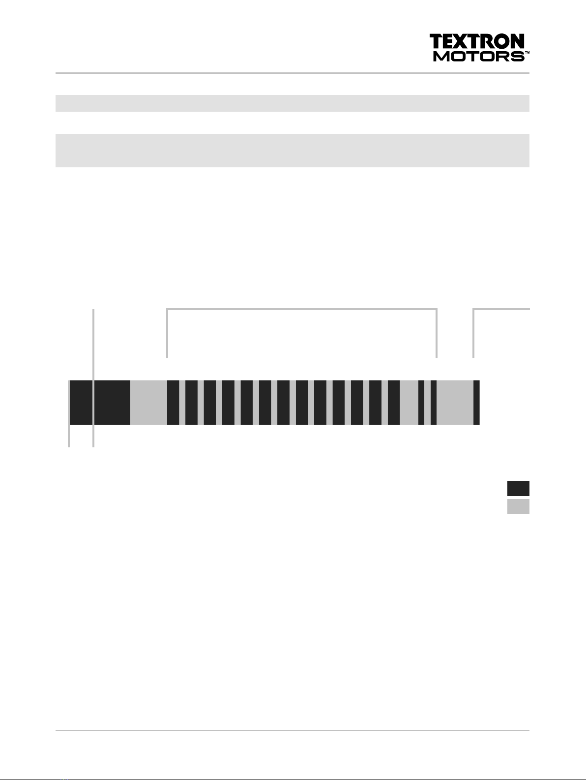
The flash codes will be displayed corresponding the following flow diagram.
Ignition ON
Light testing
Start of the
1st flash code
sequence
1st flash code = 132
13 times long illuminating corresponds to 13.
2 times short illuminating corresponds to 2.
Which trouble code corresponds to flash code 132, see chapter 5.1.3
Conversion table for flash code to trouble code.
End
of the
1st flash
code se-
quence
Start of the
2nd flash code
sequence or
restart.
3 s
1 s
1 s
1 s
1 s
1 s
1 s
1 s
1 s
1 s
1 s
1 s
1 s
1 s
0,5 s
0,5 s
...
3 s
0,5 s
0,5 s
0,5 s
0,5 s
0,5 s
0,5 s
0,5 s
0,5 s
0,5 s
0,5 s
0,5 s
0,5 s
1,5 s
0,5 s
3 s
Malfunction indicator
light (MIL)
illuminates
not illuminated
All existing flash codes will be displayed in sequence.
►Turn off ignition.
If you do not turn off the ignition after 5 complete cycles the non active trouble codes will be deleted from the
engine control unit (ECU) memory.

15DHB MPE850 MAR Rev B | 408014 | 408090 | 408101 | 408246 |
5 Troubleshooting with trouble codes
5.1 Displaying trouble codes
5.1.3 Conversion table for flash code to trouble code
Flash code Trouble code
4 P2229
5 P2228
6 C0001
7 P0501
8 P0501
9 P0016
10 P0315
11 P0370
12 P0372
13 P0373
14 P025D
15 P025C
16 P025A
17 P0246
18 P0245
19 P0244
20 P2119
21 P0500
22 P0503
23 P0032
24 P0031
25 P0030
26 P0052
27 P0051
28 P0050
29 P0687
30 P0686
31 P0685
32 P0108
33 P0107
34 P0238
35 P0237
36 P2118
37 P0812
38 P0617
39 P0616
40 P0615
Flash code Trouble code
41 P0118
42 P0117
43 P0116
44 P0113
45 P0112
46 P0114
47 P2123
48 P2122
49 P2128
50 P2127
51 P061B
52 P0132
53 P0131
54 P0130
55 P0152
56 P0151
57 P0150
58 P0123
59 P0122
60 P0223
61 P0222
62 P0659
63 P0658
64 P0643
65 P0641
66 P0653
67 P0651
68 P0692
69 P0691
70 P0691
71 P0694
72 P0693
73 P0693
74 P1502
75 P1501
76 P0857
77 P0726
Flash code Trouble code
78 P2101
79 P2101
80 P2100
81 P2103
82 P2102
83 P2103
84 P2102
85 P2103
86 P2301
87 P0351
88 P2304
89 P0352
90 P2307
91 P0353
92 P2310
93 P0354
94 P0262
95 P0261
96 P0201
97 P0265
98 P0264
99 P0202
100 P0268
101 P0267
102 P0203
103 P0271
104 P0270
105 P0204
106 P0899
107 P0888
108 P0802
109 P0219
110 P0521
111 P2299
112 P0504
113 P0504
114 P2138

16 DHB MPE850 MAR Rev B | 408014 | 408090 | 408101 | 408246 |
Flash code Trouble code
115 P0642
116 P060B
117 P0217
118 P0172
119 P0171
120 P0175
121 P0174
122 P211A
123 P063D
124 P063C
125 P063E
126 P063A
127 P063B
128 P063F
129 P0638
130 P0121
131 P0221
132 P2135
133 P0344
134 P0012
135 P0011
136 P0341
137 P0324
138 P0325
139 P0336
140 P0330
141 P0331
142 P1604
143 P0238
144 P0237
145 C0073
146 C0073
147 C0073
148 C0073
149 C0073
150 C0073
151 C0073
152 P0138
153 P0137
Flash code Trouble code
154 P0136
155 P0158
156 P0157
157 P0156
158 P0038
159 P0037
160 P0036
161 P0058
162 P0057
163 P0056
164 P2261
165 P2262
166 P0546
167 P0545
168 P0172
169 P0171
170 P0175
171 P0174
172 P0133
173 P0153
174 P0420
175 P0430
176 P0128
177 P0101
178 P2270
179 P2271
180 P227A
181 P2272
182 P2273
183 P227B
184 P0459
185 P0458
186 P0444
187 P0314
188 P0579
189 P0578
190 P0567
191 P0570
192 P0569
Flash code Trouble code
193 P0315
194 P0300
195 P0136
196 P0156
197 P0139
198 P0139
199 P0139
200 P0159
201 P0159
202 P0159
203 P0336
204 P0626
205 P0625
206 P060C
207 P0606
208 P061A
209 P061C
5 Troubleshooting with trouble codes
5.1 Displaying trouble codes

17DHB MPE850 MAR Rev B | 408014 | 408090 | 408101 | 408246 |
5 Troubleshooting with trouble codes
5.2 Description of trouble codes
5.2 Description of trouble codes
Trouble code
Displayed fault
Trouble code description
Possible consequences
Affected part/system
►Possible consequences/remedy
P0011 "A" Camshaft Position - Timing Over-
Advanced or System Performance Bank 1
Invalid signal at the sensor camshaft.
Sensor camshaft
►Check the valve timing. (See the repair
manual.)
►Check wiring in the wire harness to the
affected part. (See chapter 7 Wiring
diagram.)
►Replace the affected part. (See the repair
manual.)
P0016 Crankshaft Position – Camshaft Position
Correlation Bank 1 Sensor A
The signals sensor crankshaft and sensor
camshaft are not synchronous.
Rough engine running.
Engine does not start or stalls.
Sensor crankshaft
►Check wiring in the wire harness to the
affected part. (See chapter 7 Wiring
diagram.)
►Replace the affected part. (See the repair
manual.)
►Check the crankshaft reluctor. (See
chapter 6 Test procedures at engine.)
P0030 HO2S Heater Control Circuit Bank 1 Sensor 1
Open circuit at part or wire harness.
Loss of power.
Rough engine running.
Sensor lambda 1
►Check wiring in the wire harness to the
affected part. (See chapter 7 Wiring
diagram.)
►Replace the affected part. (See the repair
manual.)
P0031 HO2S Heater Control Circuit Low Bank 1
Sensor 1
Short circuit to ground at part or wire harness.
Loss of power.
Rough engine running.
Sensor lambda 1
►Check wiring in the wire harness to the
affected part. (See chapter 7 Wiring
diagram.)
►Replace the affected part. (See the repair
manual.)

18 DHB MPE850 MAR Rev B | 408014 | 408090 | 408101 | 408246 |
5 Troubleshooting with trouble codes
5.2 Description of trouble codes
Trouble code
Displayed fault
Trouble code description
Possible consequences
Affected part/system
►Possible consequences/remedy
P0032 HO2S Heater Control Circuit High Bank 1
Sensor 1
Short circuit to plus at part or wire harness.
Loss of power.
Rough engine running.
Sensor lambda 1
►Check wiring in the wire harness to the
affected part. (See chapter 7 Wiring
diagram.)
►Replace the affected part. (See the repair
manual.)
P0036 HO2S Heater Control Circuit Bank 1 Sensor 2
Open circuit at part or wire harness.
Loss of power.
Rough engine running.
Sensor lambda 2
►Check wiring in the wire harness to the
affected part. (See chapter 7 Wiring
diagram.)
►Replace the affected part. (See the repair
manual.)
P0037 HO2S Heater Control Circuit Low Bank 1
Sensor 2
Short circuit to ground at part or wire harness.
Loss of power.
Rough engine running.
Sensor lambda 2
►Check wiring in the wire harness to the
affected part. (See chapter 7 Wiring
diagram.)
►Replace the affected part. (See the repair
manual.)
P0038 HO2S Heater Control Circuit High Bank 1
Sensor 2
Short circuit to plus at part or wire harness.
Loss of power.
Rough engine running.
Sensor lambda 2
►Check wiring in the wire harness to the
affected part. (See chapter 7 Wiring
diagram.)
►Replace the affected part. (See the repair
manual.)

19DHB MPE850 MAR Rev B | 408014 | 408090 | 408101 | 408246 |
5 Troubleshooting with trouble codes
5.2 Description of trouble codes
Trouble code
Displayed fault
Trouble code description
Possible consequences
Affected part/system
►Possible consequences/remedy
P0101 Mass or Volume Air Flow Circuit Range/
Performance
Implausible values in air mass calculation.
Loss of power.
Starting difficulties.
Sensor intake manifold pressure/temperature
►Check wiring in the wire harness to the
affected part. (See chapter 7 Wiring
diagram.)
►Replace the affected part. (See the repair
manual.)
►Leak air in the intake system can cause the
fault. Check the intake system.
WARNING! The throttle body is a safety
critical component. Improper repair or
cleaning of the throttle body may endanger
the safety of persons. Always replace a
defective throttle body.
►Corrosion or soiling in the throttle body can
cause the fault. Check the throttle body.
(See the repair manual.)
P0107 Manifold Absolute Pressure/Barometric
Pressure Circuit Low Input
Open circuit or short circuit to ground at part or
wire harness.
Loss of power.
Starting difficulties.
Sensor intake manifold pressure/temperature
►Check wiring in the wire harness to the
affected part. (See chapter 7 Wiring
diagram.)
►Replace the affected part. (See the repair
manual.)
P0108 Manifold Absolute Pressure/Barometric
Pressure Circuit High Input
Short circuit to plus at part or wire harness.
Loss of power.
Starting difficulties.
Sensor intake manifold pressure/temperature
►Check wiring in the wire harness to the
affected part. (See chapter 7 Wiring
diagram.)
►Replace the affected part. (See the repair
manual.)

20 DHB MPE850 MAR Rev B | 408014 | 408090 | 408101 | 408246 |
5 Troubleshooting with trouble codes
5.2 Description of trouble codes
Trouble code
Displayed fault
Trouble code description
Possible consequences
Affected part/system
►Possible consequences/remedy
P0112 Intake Air Temperature Sensor 1 Circuit Low
Short circuit to ground at part or wire harness.
Loss of power.
Starting difficulties.
Sensor intake manifold pressure/temperature
►Check wiring in the wire harness to the
affected part. (See chapter 7 Wiring
diagram.)
►Replace the affected part. (See the repair
manual.)
P0113 Intake Air Temperature Sensor 1 Circuit High
Open circuit or short circuit to plus at part or
wire harness.
Loss of power.
Starting difficulties.
Sensor intake manifold pressure/temperature
►Check wiring in the wire harness to the
affected part. (See chapter 7 Wiring
diagram.)
►Replace the affected part. (See the repair
manual.)
P0116 Engine Coolant Temperature Circuit Range/
Performance
Measured data implausible.
Sensor coolant temperature
►Check wiring in the wire harness to the
affected part. (See chapter 7 Wiring
diagram.)
►Replace the affected part. (See the repair
manual.)
P0117 Engine Coolant Temperature Circuit Low
Short circuit to ground at part or wire harness.
Sensor coolant temperature
►Check wiring in the wire harness to the
affected part. (See chapter 7 Wiring
diagram.)
►Replace the affected part. (See the repair
manual.)
P0118 Engine Coolant Temperature Circuit High
Open circuit or short circuit to plus at part or
wire harness.
Sensor coolant temperature
►Check wiring in the wire harness to the
affected part. (See chapter 7 Wiring
diagram.)
►Replace the affected part. (See the repair
manual.)
This manual suits for next models
9
Table of contents
Other Textron Motors Engine manuals


Popular Engine manuals by other brands


Becker
Becker R8-17-E22 Assembly and operating instructions

Nanni
Nanni Z4.205 Operator's manual

ABB
ABB TPL71-C35 Operation manual

3T-Components
3T-Components 3T-MOTORS 3T45-20 Installation & operating instructions

NSK
NSK Megatorque Motor EGA Startup guide

Briggs & Stratton
Briggs & Stratton 120000 Operating & maintenance instructions