Textron Motors MPE 850 OFF-ROAD Operating instructions

TD409135_RLF
Rev A
04.09.2015
MPE 850 OFF-ROAD
– 409135 I2 846 UTV NA-80
This repair manual is valid for the following engine models:
en_English
REPAIR MANUAL
4-Stroke Engine
Read the introductory chapter before performing the task on the engine.
Pay particular attention to the safety messages.


Textron Motors GmbH
Daimlerstraße 5
88677 Markdorf
Germany
www.weber-motor.com
Textron Motors GmbH strives to make continual improvements as part of the ongoing technical development
of its products. All documentation is therefore subject to technical modifications.
Reprints and translations, in whole or in part, require written permission from Textron Motors GmbH.
All rights reserved according to the copyright law.

4 RLF MPE850 Rev A | 409135 |
Table of contents
Table of contents
1 About this document 9
1.1 Meaning of the symbols and signal words........................................ 9
1.2 Change management .......................................................9
1.3 Finding the required information ..............................................10
2 Safety 11
2.1 Meaning of the safety alert symbol and signal words .............................. 11
2.2 Important safety messages .................................................. 12
3 Basic instructions for working on the engine 15
3.1 Before you begin working ...................................................15
3.1.1 Removing engine from vehicle ..............................................15
3.2 While working ............................................................15
3.2.1 Lift and transport the engine................................................15
3.2.2 Secure the engine while working ............................................15
3.2.3 Tightening torque ........................................................ 16
3.2.4 Cleaning ...............................................................16
3.2.5 Disposal ...............................................................16
3.3 After working .............................................................16
3.3.1 Updating engine control unit calibration ....................................... 16
3.3.2 Checking the work carried out ..............................................16
4 Tools and accessories 17
4.1 Equipment workshop .......................................................17
4.1.1 Textron Motors special tools ................................................17
4.1.2 Textron Motors Diagnostic Tool.............................................. 18
4.1.3 Commercially available workshop equipment and standard tools ...................18
4.1.4 Commercially available special tools .........................................20
4.1.5 Supplies ...............................................................21
5 Overview of activities 22
010 Crankcase ..............................................................22
010.01-1 Crankcase ..........................................................22
Replacing crankcase.........................................................22
Replacing welch plugs .......................................................22
Replacing tie rod ............................................................22
Replacing plugs ............................................................22
010.01-2 Crankcase NA .......................................................22
Replacing cylinder liners ......................................................22
Replacing oil seal ...........................................................23
Replacing plug .............................................................23
010.01-3 Crankcase ..........................................................23
Removing plug .............................................................23
Installing plug ..............................................................23

5RLF MPE850 Rev A | 409135 |
Table of contents
Replacing plugs ............................................................23
Removing fitting ............................................................23
Installing fitting .............................................................23
Removing sensor crankshaft ..................................................23
Installing sensor crankshaft ...................................................23
Removing sensor knock ......................................................23
Installing sensor knock .......................................................23
010.02-1 Oil cooler bracket ..................................................... 24
Removing oil cooler bracket ...................................................24
Installing oil cooler bracket ....................................................24
010.02-2 Oil cooler bracket ..................................................... 24
Replacing blanking cover .....................................................24
Replacing plug .............................................................24
Sealing cover oil cooler bracket ................................................24
010.03 Generator cover........................................................ 24
Removing generator cover ....................................................24
Installing generator cover .....................................................24
Replacing generator cover ....................................................24
Replacing oil seal ...........................................................25
Replacing vent plug .........................................................25
020 Crank drive ..............................................................25
020.01 Crankshaft ............................................................25
Removing crank drive ........................................................25
Installing crank drive .........................................................26
Replacing crankshaft ........................................................26
Replacing balance shaft ......................................................26
Removing pistons and con rods ................................................26
Installing pistons and con rods .................................................27
Replacing piston ............................................................27
Replacing con rod ...........................................................27
Checking con rod bearing play .................................................27
Checking main bearing play ...................................................27
020.02 Stub shaft ............................................................27
Removing stub shaft .........................................................27
Installing stub shaft ..........................................................27
020.03 Abdeckung Kurbelwelle ..................................................28
Removing crankshaft cover....................................................28
Installing crankshaft cover ....................................................28
030 Cylinder head ............................................................28
030.01 Valve cover ........................................................... 28
Removing valve cover........................................................28
Installing valve cover.........................................................28
Replacing valve cover........................................................28
Removing ignition coils .......................................................28
Installing ignition coils ........................................................28
Removing sensor camshaft....................................................28
Installing sensor camshaft ....................................................28
030.02 Cylinder head .........................................................29
Removing cylinder head ......................................................29
Installing cylinder head .......................................................29
Replacing cylinder head ......................................................29
Removing spark plugs........................................................29

6 RLF MPE850 Rev A | 409135 |
Table of contents
Installing spark plugs ........................................................30
Removing switch oil pressure ..................................................30
Installing switch oil pressure ...................................................30
Removing fitting ............................................................30
Installing fitting .............................................................30
Replacing plugs ............................................................30
040 Valve train............................................................... 30
040.01 Camshaft .............................................................30
Replacing camshaft..........................................................30
Replacing timing chain .......................................................31
Checking and setting valve timing ..............................................31
Replacing chain rail..........................................................31
Replacing chain guide........................................................31
040.02 Rocker arms ..........................................................31
Replacing rocker arms .......................................................31
040.03 Valves ...............................................................32
Removing valve.............................................................32
Installing valve..............................................................32
050 Cooling system ...........................................................32
050.01 Thermostat housing.....................................................32
Removing thermostat housing .................................................32
Installing thermostat housing .................................................. 32
Removing fitting ............................................................32
Installing fitting .............................................................32
Replacing thermostat ........................................................33
Replacing sensor coolant temperature ...........................................33
Replacing plug thermostat housing..............................................33
Removing closing cap thermostat housing ........................................33
Installing closing cap thermostat housing .........................................33
050.02 Coolant pump .........................................................33
Removing impeller ..........................................................33
Installing impeller ...........................................................33
Removing coolant pump ......................................................34
Installing coolant pump .......................................................34
050.03 Oil cooler .............................................................34
Removing oil cooler..........................................................34
Installing oil cooler...........................................................34
060 Exhaust system ..........................................................34
060.01 Mounting exhaust manifold ............................................... 34
Removing/Installing exhaust system.............................................34
Replacing studs.............................................................34
070 Intake area .............................................................. 35
070.01 Intake manifold ........................................................35
Removing intake manifold.....................................................35
Installing intake manifold......................................................35
Replacing intake manifold.....................................................35
Removing sensor intake manifold pressure/temperature .............................35
Installing sensor intake manifold pressure/temperature ..............................35
Replacing cap ..............................................................35
070.02 Mounting throttle body ...................................................35
Removing throttle body .......................................................35
Installing throttle body ........................................................35

7RLF MPE850 Rev A | 409135 |
Table of contents
Replacing throttle body .......................................................35
Replacing rubber mount ......................................................35
080 Engine management system ................................................ 36
Sensor crankshaft ...........................................................36
Sensor camshaft ............................................................36
Sensor coolant temperature ...................................................36
Sensor lambda .............................................................36
Sensor intake manifold pressure/temperature NA ..................................36
Sensor knock ..............................................................36
Engine control unit NA .......................................................36
Ignition coils ...............................................................36
Spark plugs ................................................................36
Injectors NA................................................................36
Throttle body ...............................................................36
Switch oil pressure ..........................................................36
090 Starter, Generator......................................................... 36
090.01 Starter ...............................................................36
Removing starter............................................................36
Installing starter.............................................................36
Replacing starter............................................................36
090.02 Generator ............................................................37
Removing generator .........................................................37
Installing generator ..........................................................37
090.03 Voltage regulator ....................................................... 37
Removing/Installing voltage regulator............................................37
090.04 Relay starter ..........................................................37
Removing/Installing relay starter ...............................................37
100 Fuel system .............................................................37
100.01 Fuel rail ..............................................................37
Removing fuel rail ...........................................................37
Installing fuel rail ............................................................37
Replacing injector . . . . . . . . . . . . . . . . . . . . . . . . . . . . . . . . . . . . . . . . . . . . . . . . . . . . . . . . . . . 37
110 Lubrication system ........................................................ 37
110.01 Dry sump ............................................................. 37
Removing suction pump cover .................................................37
Installing suction pump cover ..................................................37
Replacing suction pump cover .................................................38
Removing oil suction pump....................................................38
Installing oil suction pump.....................................................38
Stutzen ersetzen ............................................................38
Removing intermediate gear suction pump .......................................38
Installing intermediate gear suction pump ........................................38
110.02 Oil pressure pump ......................................................39
Removing oil pressure pump ..................................................39
Installing oil pressure pump ...................................................39
110.03 Oil pressure valve ...................................................... 39
Removing oil pressure valve...................................................39
Installing oil pressure valve....................................................39
110.04 Oil filter...............................................................39
Removing oil filter . . . . . . . . . . . . . . . . . . . . . . . . . . . . . . . . . . . . . . . . . . . . . . . . . . . . . . . . . . . 39
Installing oil filter . . . . . . . . . . . . . . . . . . . . . . . . . . . . . . . . . . . . . . . . . . . . . . . . . . . . . . . . . . . . 39
Removing threaded sleeve ....................................................39

8 RLF MPE850 Rev A | 409135 |
Table of contents
Installing threaded sleeve .....................................................40
110.05 Oil tank...............................................................40
Removing/Installing oil tank ...................................................40
120 Engine mount ............................................................40
120.01 Lifting eye ............................................................40
Removing bracket on the drive side .............................................40
Installing bracket on the drive side ..............................................40
Removing pipe clamp . . . . . . . . . . . . . . . . . . . . . . . . . . . . . . . . . . . . . . . . . . . . . . . . . . . . . . . . 40
Installing pipe clamp .........................................................40
Removing bracket across from the drive side......................................40
Installing bracket across from the drive side.......................................40
6 Working instructions, single 41
6.1 List of working instructions, single .............................................41
Appendix 231
Overview of revisions ..........................................................231
Index ......................................................................232
This repair manual describes how to safely and correctly remove, install and replace engine components.
Observe the following information:
– Read through the service manual before performing any tasks.
– Some figures in this repair manual are general illustrations and may differ from the actual engine.
1 About this document
1.1 Meaning of the symbols and signal words
Item Meaning
NOTICE The signal word NOTICE indicates potential property damage.
Information The signal word Information indicates specific features and recommendations.
For the activity required special tools.
For the activity additionally required spare parts.
For the activity required supplies.
For the activity additionally required documents.
1About this document
1.1 Meaning of the symbols and signal words | …
1.2 Change management
Textron Motors GmbH strives to make continual improvements as part of the ongoing technical development
of its products. You may find that descriptions in the repair manual are changed or amended. All changes are
described in the chapter Overview of revisions.
Observe the following information:
– Always use the most current repair manual from the protected area on our web site
www.weber-motor.com.
– Always print the required chapter and all chapters referred to completely and then destroy the printouts.
9
RLF MPE850 Rev A | 409135 |

1About this document
1.3 Finding the required information
1.3 Finding the required information
►Open chapter 5 Overview of activities in
the repair manual.
►Locate the section with the same
designation 010.01-2 Crankcase NA 3.
In this section you will find the activity
Replacing cylinder liners 5.
►Check whether the activity is valid for the
engine model 4.
►Perform all for the activity required working
instructions 6in the order shown.
Observe the following references:
– A list of all working instructions is located in
chapter 6.1 List of working instructions,
single.
– Each working instruction contains information
on required special tools, additional required
spare parts, supplies and documents.
When you planning a work on the engine, proceed
as follows:
For example, you want to replace the cylinder
liners 2.
►Identify the corresponding component in the
spare parts catalog..
The cylinder liners can be found in the spare
parts catalog in chapter
010.01-2 Crankcase NA 1
10 RLF MPE850 Rev A | 409135 |
2
3
4
5
6
1
11RLF MPE850 Rev A | 409135 |
This engine is state-of-the-art and built according to recognized safety-technical regulations. Ignoring the
information in this repair manual may result in personal injury or property damage.
This repair manual is solely intended for use in a workshop authorized by Textron Motors or the vehicle
manufacturer. All work on the engine must be performed by appropriately trained personnel.
Before beginning any work, trained personnel authorized to work on the engine must have access to the
complete documentation of the engine. Make sure that trained personnel have read and understand all
introductory chapters and in particular, the chapter on safety.
Observe all generally applicable laws and regulations in addition to the information in this repair manual:
– accident prevention
– environmental protection
– handling of hazardous materials
– personal safety equipment
– traffic laws
2 Safety
2.1 Meaning of the safety alert symbol and signal words
Item Meaning
The safety alert symbol draws your attention to possible dangers.
WARNING
The signal word WARNING indicates a potentially dangerous situation that may
lead to a serious or fatal injury.
CAUTION
The signal word CAUTION indicates a potentially dangerous situation that may
lead to a minor or moderately severe injury.
2Safety
2.1 Meaning of the safety alert symbol and signal words

12 RLF MPE850 Rev A | 409135 |
2.2 Important safety messages
2Safety
2.2 Important safety messages
You endanger the safety of personnel if you do not perform work exactly
as described in this repair manual.
►Do not deviate from the working instructions in this repair manual.
►Pay attention to the safety messages in the vehicle manufacturer’s
documentation.
Engine malfunctions can cause pose a safety risk to persons.
►Only operate the engine in perfect condition.
Defective engine components can cause serious engine damages and
pose a safety risk to persons.
►Check all components before installation.
►Always replace defective components.
Work performed incorrectly poses a safety risk to personnel.
►Check the vehicle safety each time after working on the engine.
(See chapter 3.3.2 Checking the work carried out.)
All the components in your engine have been carefully tested and fulfill
strict quality and safety requirements.
►Textron Motors offers spare parts to the highest quality. Ensure that
equivalent spare parts corresponds with this quality requirements.
Engine modifications may pose a safety risk to persons.
►Do not install add-on parts or modify the engine.
Spinal column injury due to incorrect lifting of heavy loads.
►Always use a workshop crane to lift and transport the engine on the
brackets provided. (See chapter 3.2 Lift and transport the engine.)
Crush injuries due to the engine overturning.
►Mount the engine to the engine stand before starting any work.
(See chapter 3.2.2 Secure the engine while working.)
Unsuitable tools and accessories pose a safety risk to personnel.
►Always use tools listed in chapter 4 Tools and accessories.
Working instructions
Malfunctions
Defective components
Checking the work carried out
Spare parts
Add-on parts and modifications
Lift and transport the engine.
Securing the engine
Tools and accessories

13RLF MPE850 Rev A | 409135 |
2Safety
2.2 Important safety messages
Missing protective equipment poses a safety risk to personnel.
►Attach all protective equipment after completing the tasks.
Engine components become extremely hot during operation.
►Do not touch any engine components during operation.
►Switch off the engine and wait until the components have cooled.
The engine must be disconnected from the power supply before any work
is carried out. Leaving the engine connected to the power supply poses a
risk to personnel.
►Only reconnect the power supply when prompted to do so by the
vehicle manufacturer.
►Pay attention to the safety messages in the vehicle manufacturer’s
documentation.
Engine exhaust gases contain carbon monoxide (CO). Inhalation of
carbon monoxide can deprive the body of oxygen and result in organ
damage or death by asphyxiation.
►Never operate the engine in enclosed spaces.
Engine fluids pose a health risk.
►Always read the manufacturer's instructions.
►Always wash your hands prior to eating, smoking and using the
restroom as well as at the end of the working shift when working
with engine fluids.
Engine fluids are hazardous to the environment.
►Never allow engine fluids to escape into the groundwater, water
courses or sewage system. Always dispose of engine fluids
according to applicable regulations.
Danger of slipping on spilled fluids.
►Always use a filler neck or funnel when filling the engine with fluids.
►Always clean up any spilled engine fluids immediately.
Fuel is highly flammable. Vapors may ignite and cause an explosion.
►Do not smoke in the vicinity of the engine and do not allow open
flames or sparks near the engine or the fuel system.
►Always turn off the engine before fueling.
►Never fill with fuel while the engine is running.
►Do not start the engine if you smell fuel or see a fuel leak.
►Fuel on hot surfaces can cause fires.
►In the event of a fire, use foam, dry chemical or carbon dioxide fire
extinguishers. Do not extinguish with water.
Protective equipment
Hot engine components
Engine power supply
Engine exhaust gases
Fuel, engine oil and coolant
handling
Fuel

14 RLF MPE850 Rev A | 409135 |
2Safety
2.2 Important safety messages
Engine oil is flammable and can emit toxic gases.
►Do not smoke in the vicinity of the engine and do not allow open
flames or sparks near the engine.
►Engine oil on hot surfaces can cause fires.
►In the event of a fire, use foam, dry chemical or carbon dioxide fire
extinguishers. Do not extinguish with water.
Engine oil

15RLF MPE850 Rev A | 409135 |
1
1
See the vehicle manufacturer‘s documentation.
3Basic instructions for working on the engine
3.1 Before you begin working | 3.2 While working
3 Basic instructions for working on the engine
The following requirements must be met before performing any tasks:
– The engine has been removed from the vehicle.
– The engine has been disconnected from the power supply.
– There is no engine oil or coolant in the engine.
– The engine is in original factory condition. You identify the factory condition in the spare parts catalog.
3.1 Before you begin working
3.1.1 Removing engine from vehicle
3.2 While working
WARNING! Spinal column injury due to
incorrect lifting of heavy loads. Always lift the
engine using a workshop crane.
NOTICE! Components can break. Lift the engine
only using the brackets.
►Lift the engine using the brackets 1.
3.2.1 Lift and transport the engine
WARNING! Crush injuries due to the engine overturning. Mount the engine to the engine stand before
starting any work.
If not otherwise specified, mount the engine on the drive side or across from the drive side. (See
chapter 000.01 Mount the engine on the engine stand.)
3.2.2 Secure the engine while working

16 RLF MPE850 Rev A | 409135 |
3Basic instructions for working on the engine
3.2 While working | 3.3 Checking the work carried out
When disposing of operating materials, replaced parts or the whole engine, always comply with the relevant
applicable national laws and guidelines.
3.2.5 Disposal
For all details about tightening torque in this repair manual, observe the following information:
– If not otherwise specified, threads are dry and free of engine oil.
– For components with coated threads, the tightening torques always refer to new components.
3.2.3 Tightening torque
Observe the following information:
– Before assembling components, clean all joint surfaces.
– If there is contamination in the lubrication system, cooling system or fuel unit, clean all components
concerned.
3.2.4 Cleaning
Check the engine when installed again in the vehicle.
►Turn the ignition on for about a minute, until the throttle body opens and closes again.
►Allow the engine to warm up as described in the service manual of the engine. You should not hear
any unusual noises.
►Perform a visual inspection. No fluids should be escaping.
►Run the engine through all operating modes.
3.3.2 Checking the work carried out
Update the calibration of the engine control unit when engine installed again in the vehicle.
►Update the engine control unit calibration. (See the Textron Motors Diagnostic Tool manual.)
►Clear the trouble codes. (See the Textron Motors Diagnostic Tool manual.)
3.3.1 Updating engine control unit calibration
3.3 After working

17RLF MPE850 Rev A | 409135 |
4Tools and accessories
4.1 Equipment workshop
4Tools and accessories
Textron Motors offers a tool case that contains the following Textron Motors special tools. Visit our web site
www.weber-motor.com for more information.
4.1.1 Textron Motors special tools
Figure Description
Locking tool crankshaft
Chain tool
Installation spike valve
stem seal
Remover bearing cap
Figure Description
TDC-adjusting tool
Assembling kit oil seal
crankshaft
Pin punch axle
intermediate gear
Assembling kit slide
ring seal
4.1 Equipment workshop

18 RLF MPE850 Rev A | 409135 |
4Tools and accessories
4.1 Equipment workshop
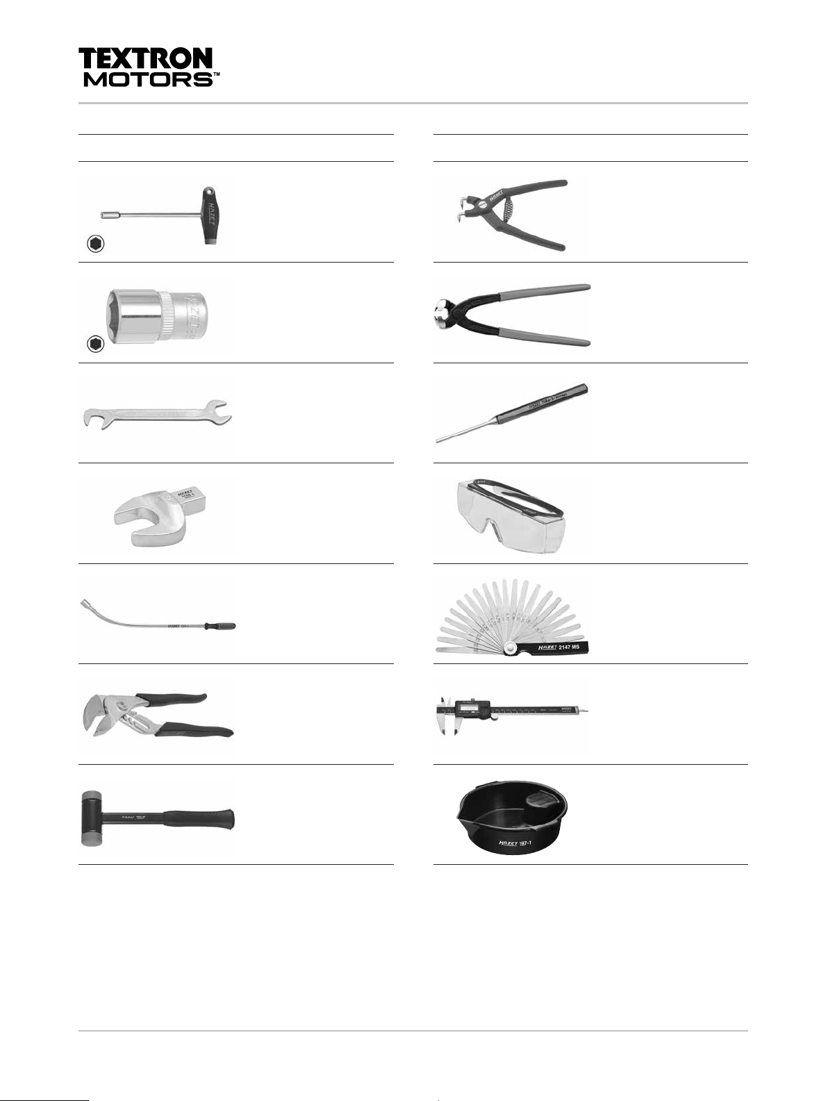
4.1.3 Commercially available workshop equipment and standard tools
Abbildung Bezeichnung
Workshop crane with
carrying strap
Minimum lifting
capacity 300 kg
[650 lb]
Engine stand
Minimum lifting capacity
300 kg [650 lb]
Mounting bolts M6 and
M10
Torque wrench
0,5 – 80 Nm
[0.4 – 59 lbf ft]
with extension and
insert adapter
Reversible ratchet
with extension and
insert adapter
Abbildung Bezeichnung
Torx® screwdriver
T20, T30, T45
Torx® screwdriver
socket
T20, T30, T45
Hexagon screwdriver
4, 5, 6, 7, 8
6-point socket
4, 5, 6, 7, 8
In addition to the Textron Motors special tools, you will require the following tools and accessories. The
figures are only examples of suitable tools. All tools and accessories are available from specialist retailers.
Textron Motors offers a diagnostic case that
contains the Textron Motors Diagnostic Tool. The
Textron Motors Diagnostic Tool is designed for fault
diagnostics and service tasks for Textron engines
using a Synerject engine management system.
Visit your local vehicle dealer or our web site
www.weber-motor.com for more information.
4.1.2 Textron Motors Diagnostic Tool
19RLF MPE850 Rev A | 409135 |
4Tools and accessories
4.1 Equipment workshop
Abbildung Bezeichnung
Hexagon nut-driver
7
6-point socket wrench
7, 10, 12, 14
Open-end wrench
7, 12, 15, 19, 22, 24,
27
Insert open-end
wrench
7, 12, 15, 16, 19, 22,
24, 27
Bar magnet
Universal pliers
Plastic hammer
Abbildung Bezeichnung
Lockring pliers (bore
holes)
Clamp pincer
Pin punch
5, 7, 8
Protective glasses
Feeler gauge
0,05 – 2 mm
Caliper
Measuring accuracy
0,05 mm
Drip tray
20 RLF MPE850 Rev A | 409135 |
4Tools and accessories
4.1 Equipment workshop
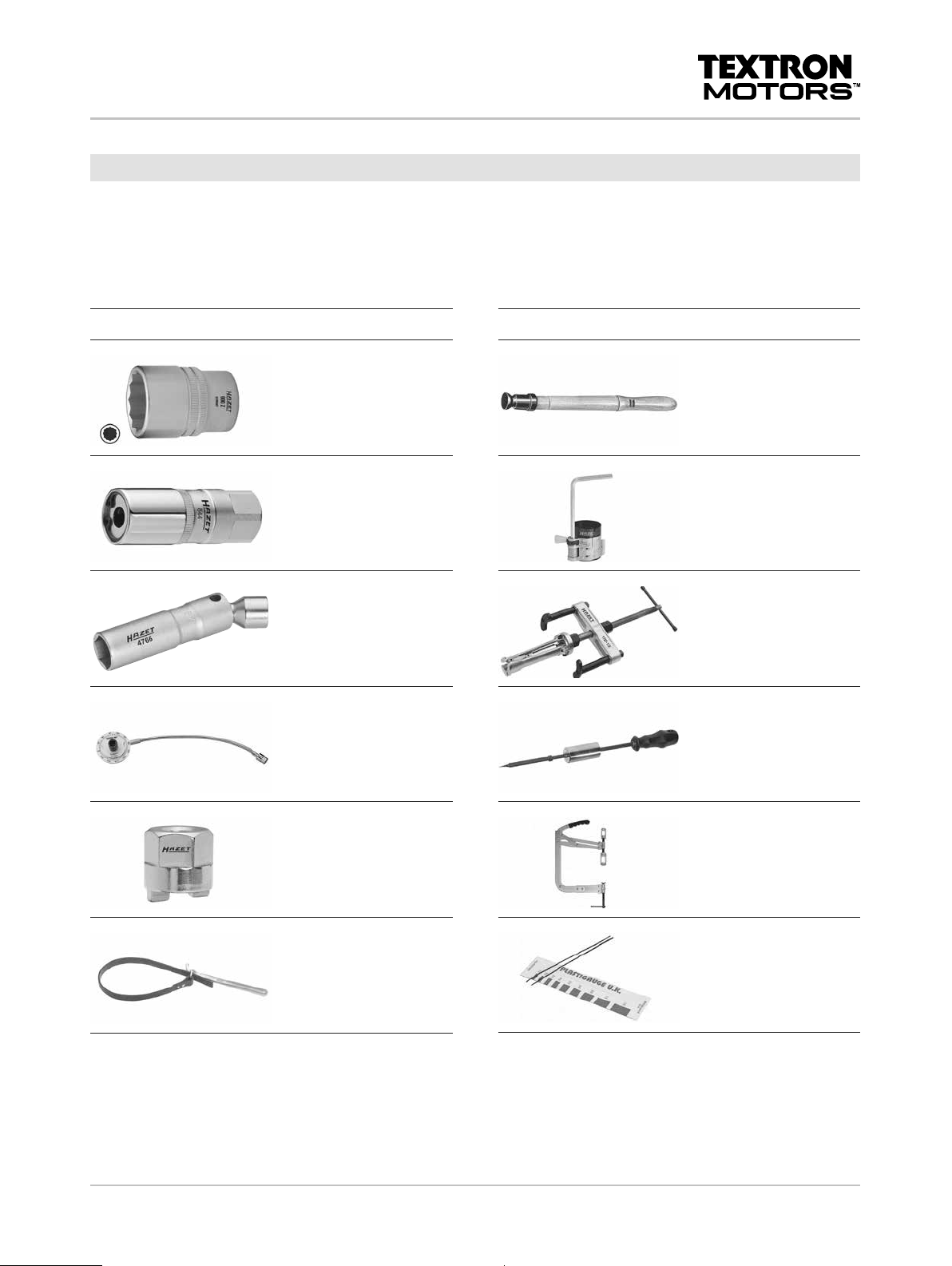
4.1.4 Commercially available special tools
Abbildung Bezeichnung
12-point socket
wrench
12
Stud extractor
8, 10
Spark plug wrench
Wrench size 16 mm
[5/8“]
Diameter: maximum
22 mm [0.87 in]
Angle indicator
Crown wrench
Width of pins
maximum 3 mm
Universal strap wrench
Abbildung Bezeichnung
Valve refacer
Piston ring compressor
Cylinder liner puller
Oil seal slide hammer
Valve spring
compressor
Precision clearance
gauges
0,025 mm - 0,04 mm
In addition you will require the following commercially available special tools. In the working instructions will
be separately referred on these special tools. The figures are only examples of suitable tools. All tools and
accessories are available from specialist retailers.
Other manuals for MPE 850 OFF-ROAD
1
Table of contents
Other Textron Motors Engine manuals


Popular Engine manuals by other brands


Mazda
Mazda L8 Workshop manual

Simu
Simu T5 AUTOSHORT BHz Series Original instructions

Doosan
Doosan D1146 Installation operation & maintenance

Continental Motors
Continental Motors TSI0L-550-C Operation, maintenance & installation manual

Rotax
Rotax 914 F Maintenance manual

Hyundai Seasall
Hyundai Seasall S250S Workshop manual


