TG drives TGA-24-9/20 User manual

1
DIGITAL SERVOAMPLIFIER
TGA-24-9/20
Instruction manual
Edition 06/2012
servotechnics
2
Type description:
TGA-24-9/20 standard version
TGA-24-9/20-O1 optional communication connector X1 – 8 pin
TGA-24-9/20-O3 optional supply voltage 48VDC
TGA-24-9/20-O4 analog input
± 10V
TGA-24-9/20-O8 lite version design

3
Safety instructions
•Read this documentation before carying out instalation. Incorrect handling of the
servoamplifier can lead to personal injury or material damage.
•The servoamplifier contain electrostatically sensitive components which may be
damaged by incorrect handling. Ground yourself before touching the
servoamplifier.
•Do not open the units. Keep all cover and switchgear cabinet doors closed during
operation.
•Servoamplifiers may have hot cooling surfaces during operation.
•Never undo the electrical connections to the servoamplifier while it is live. There
is danger of electric arcing with damage to contacts.
European directives and standards
Servoamplifiers are components, which are intended to be incorporated into electrical
plants and machines for industrial use.
When the servoamplifiers are built into machines or plants, the intended operation of
the amplifier is forbidden until it has been established that the machine or plant
fulfills the requirements of the EC Directive on Machines 98/37/EC and the EC
Directive on EMC (89/336/EEC).
The manufacturer of of the machine or plant is responsible for ensuring that they
meet the limits which are required by the EMC regulations.
CE – conformance
Conformance with the EC Directive on EMC 89/336/EEC is mandatory for the
supply of servoamplifiers within the European Cummunity.
The servoamplifiers TGA-24 have been tested by an authorized testing laboratory in a
defined configuration with the system components which are described in this
documentation. Any divergence from the configuration anf installation described in
this documentation means that you will be responsible for the performance of new
measurements to ensure that the regulatory requirements are met.
Prescribed use of the servoamplifier
The servoamplifiers are components which are built into electrical equipment or
machines, and can only be used as integral components of such equipment.
The servoamplifiers TGA-24 is only intended to drive with specific brushless
synchronous servomotors, with closed-loop control of torque, speed and/or position.
The servoamplifiers may only be operated in a closed switchgear cabinet, taking into
account the ambient conditions in technical specification. Use only copper wire. Wire
size may be determined from EN60204.
We only guarantee the conformance of the servoamplifiers with the standards for
industrial areas, if the components (motors, cables, amplifiers etc) are delivered by
TG Drives s.r.o.
4
Technical data
Parameters Unit
Data
Rated supply voltage V = 24 (15 - 42)
option O3: 48
Rated installed load for S1 operation W 230
Rated output current A
rms
9
Peak output current (max. ca 5 s) A
rms
18,5
Overvoltage protection treshold (transil) V 47
Dissipation at rated load W 20
Fusing
Supply 24 VDC – internal
– external – T 10 A
– C 8 A
Inputs / outputs
Analog input, resolution 12 bit
Input resistance V 0 - 5
option O4: ±10
k
Ω
15
Digital inputs with adjustable function 24 VDC
qty 8
V low 0 .. 5 / high 7 .. 30
mA 6
Digital outputs with adjustable function,
24 VDC, PNP
qty 4
V max. 42
mA 25
Counter inputs for IRC or stepper-motor signals
– 5V (RS422)
Connectors
Control signals
–
Interhart 3.81, 1.5mm
2
Power – Interhart 5.08, 2.5mm
2
Resolver input – Interhart 3.81, 1.5mm
2
Communication – SubD 9-pole plug
option O1
8-pole Interhart 3.81
Mechanical
Weight kg 0.6
RoDimensions without connectors mm 157
×
86
×
40
Environment
Operating temperature °C 0 - 40
Relative humidity % max. 85

5
Instalation
Dimensions
Material: 2 or 4 screws M4
6
Interfaces description
7
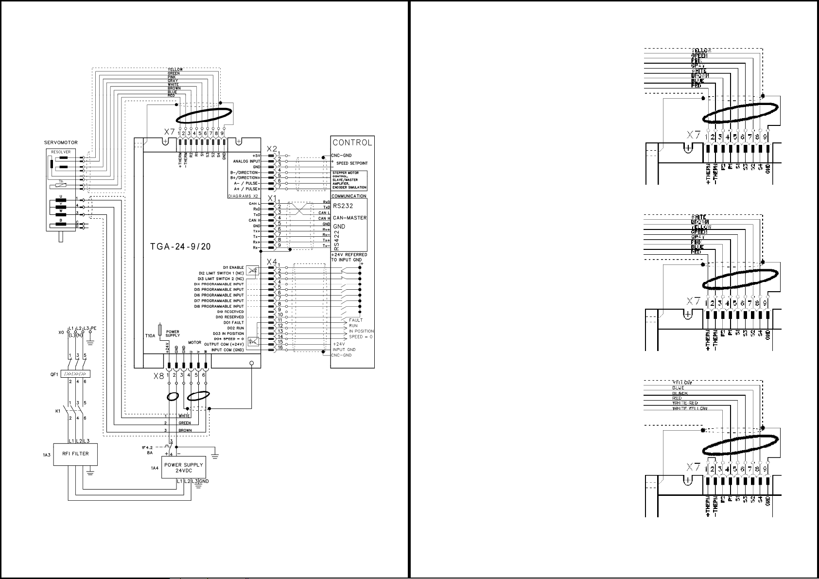
Recommended connection diagram
The ferrite rings use to decrease the
electromagnetic noice.
The unscreened ends of the cabels should
be as short as possible.
8
Resolver cable connection (X7)
The resolver cable connection for
TGT1,TGT2, TGT3,TGH2,TGH3
servomotors with the cable glands
The resolver cable connection for
TGT1,TGT2, TGT3,TGH2,TGH3
servomotors with the round
connectors
The resolver cable connection for
TGH0 servomotors with the flying
leads
9
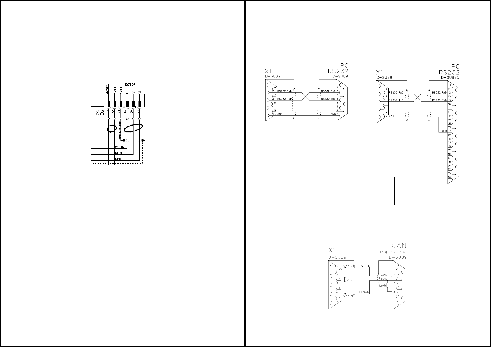
Motor cable connection (X8)
Motor cable connection for TGT1, TGT2, TGT3, TGH2 and TGH3 servomotors is
described in the chapter Recommended connection diagram (page 7). For TGH0
(only) with the flying leads is valid following motor connection:
10
RS232 interface, PC connection (X1)
The setting of the regulator parameters, inputs/outputs setting, position control and
position profiles can be carried out with an ordinary commercial PC.
Connect the PC interface (X1) of servoamplifier while the supply to the equipment is
switched off via a normal commercial 3-core null-modem cable to a serial interface
on the PC (see the diagrams below).
CAN-BUS interface
To meet ISO11898 you should use a bus cable
with a characteristic impedance of 120 Ω.
The maximum usable cable length for reliable communication
decreases with increasing transmission speed.
Cable length, depending on the transmission rate
Transmission rate (kbaud) max. cable lngth (m)
1 000 20
500 70
250 115
For EMC reasons, the SubD connector housing must fulfill the following conditions:
−metal or metalized housing
−provision for cable shielding connection
in housing, large-area connection

11
Connection to stepper-motor controller
(X2)
This interface can be used to connect the
servoamplifier to a stepper-motor controller
with 5V signal level. The value of R
according to line impedance: 150Ω– 1kΩ.
Interface for encoder input (X2)
This interface can be used to operate
the servoamplifier as a slave,
mastered by an encoder with RS422
signals level in gearing mode or by
another servoamplifier (electronic
gearing)
Interface for encoder simulation
(X2)
This interface can be used to output
incremental position value (RS422
signals level) in all of the operation
modes as feedback for the control
system or as setpoint position in
Master-Slave operation.
TG Drives, s.r.o.
Jeneweinova 37
617 00 Brno
Czech republic
www.tgdrives.com
phone: 00420 545 234 935
fax:
00420 545 234 735
This manual suits for next models
4
Table of contents


