TGB BLADE 1000 EPS IRS 4X4 User manual
1
BLADE 1000 EPS IRS 4X4
BLADE 1000 EPS SE IRS 4X4
Recreation Utility Vehicle
Assembly Man al

2
Foreword
This Assembly Manual contains the
information required for the correct assembly
of this TGB vehicle prior to delivery to the
customer. Since some external parts of the
vehicle have been removed at TGB factory for
the convenience of pac ing, assembly by the
TGB dealer is required. It should be noted that
the assembled vehicle should be thoroughly
cleaned, chec ed, and adjusted prior to
delivery to the customer.
If the style and construction of the TGB vehicle
are different from that of the photos, pictures
shown in this manual, the actual vehicle shall
prevail. Specifications are subject to change
without notice.
NOTICE
The service specifications given in this
assembly manual are based on the model as
manufactured. Modifications and significant
changes in specifications and/or procedures
will be forwarded to authorized
dealers.
The procedures below are described in the
order that the procedures are carried out
correctly and completely. Failure to do so can
result in poor performance and possible harm
to the vehicle and/or rider.
Particularly important information is
distinguished in this manual by the following
notations.
Warning
Means that serious injury or even death may
result if procedures are not followed.
Caution
Means that equipment damages may result if
procedures are not followed.
Please see the content for quic having the
special parts and system information.

3
Table of Contents
PAGE
CONTENT
5 Symbols Used on Outer Cover
6 Crate Handling
6-7 Uncrating
8-11
Parts Chec
12-13
Assembly (Shock Absorber)
13 Assembly (Rear A-arm Protector Cover)
13 Assembly (Wheels)
13-14
Assembly (Han lebar)
14 Assembly (Han lebar Cover / Han Guar )
15 Assembly (Shift Hol er)
15 Assembly (Front Bumper)
15 Assembly (Rear Han Hol )
15 Assembly (Rear Carrier)

4
Table of Contents
PAGE
CONTENT
16 Assembly (Muffler Ornamental Cover)
16 Assembly (Seat)
16 Assembly (Battery)

5
Symbols Used on O ter Cover
(1) Indicates correct upright position of the transport pac age.
(2) Transport pac age must be ept away from rain.
(3) Contents of the transport pac age are fragile, therefore the pac age must be handled with care.
(4) Up to 4 of the transport pac ages can be piled up.
(5) Do not insert from the symbol position of the transport pac age.
(6) Indicates correct insert position of the transport pac age.
(1)
(2)
(3)
(4)
(5)
6
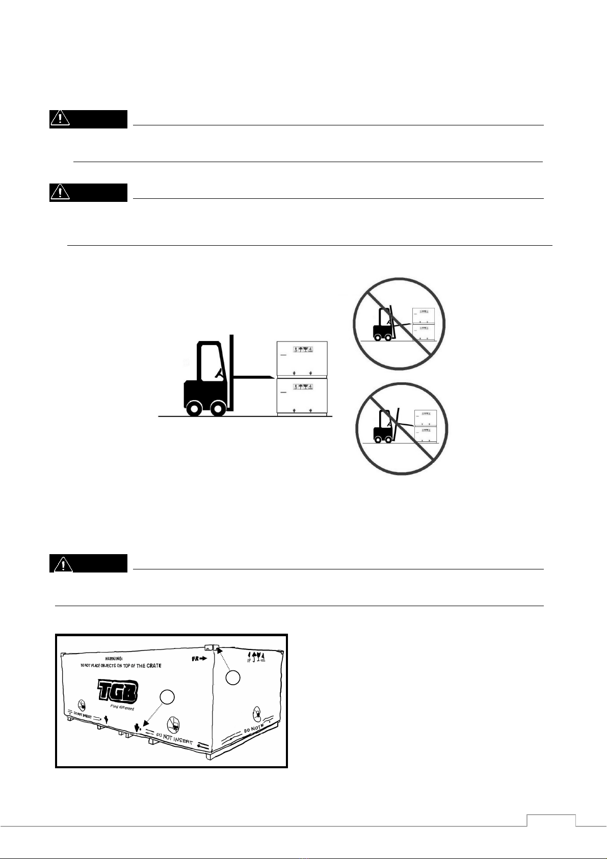
Crate Handling
Warning
1. Always handling the crated vehicle by a for lift, include stac ing/un-stac ing and storing.
2. Never stac ing up over the indicated high shown on the crate outer cover.
Caution
1.
Insert the for according to the indication position where shown on the crate outer cover.
2. Insert the for as shown below, the for must be horizontal into the crate pallet. The operation
with angles will damage the vehicle and created components.
Uncrating
Warning
Crates have sharp edges and may have nails or screws that can cause cuts and injury. Always wear
protective gloves, boots and eye protection when uncrating to prevent injury.
1. Remove 4 corner cage ends (A), and rivets
(B), and then remove the outer cover.
A
B

7
2. Remove top cage braces (A), and be careful
to avoid damage to the vehicle plastics and
the seat leather during the action.
3. Remove the bolts (A), and then lay down LH
& RH side diagonal braces (B) to disengage
its soc ets from the pallet.
Warning
Remove the bolts while holding the frame.
4. Lay down Front & Rear diagonal braces (A)
to disengage its soc ets from the pallet.
5. Remove the bolt and rear carrier brac et (A)
which be fixed the vehicle on the pallet.
A
A
B
A
A

8
Parts Check
Note
There may be minor differences in appearance between these illustrations and the actual
vehicle parts.
Remove the parts and chec the crate base and pac aged materials carefully for lost parts.
Chec the parts against the illustrations. In the following charts under Remar s, D=diameter in
millimeters, and L=length in millimeters, and P=Pitch. In the following charts under
Qty,( )component of assembly parts.
NO Part Name Qty Remar
1 Front Wheel Assy. 2 AT 26 x 8 - 14
Rear Wheel Assy. 2 AT 26 x 10 - 14
Wheel Nut 16
Rubber Cap 4
2 Battery 1 12V 18AH
3 Front Bumper Comp. 1
4 Rear Hand Hold 1
1
2
3
4

9
NO Part Name Qty Remar
1 Rear Shoc Absorber 2
Shoc Absorber Bolts 4 D=10, L=48, P=1.25
Shoc Absorber Nuts 4 D=10, P=1.25
2 Rear A-arm Protector Cover (LH) 1
Rear A-arm Protector Cover (RH) 1
Rear A-arm Protector Cover Bolts 4 D=6, L=16
3 Muffler Ornamental Cover 1
Hex. Soc et Bolts 3
4 Rear Carrier Comp. 1
Bolt 4 D=8, L=18, P=1.25
Passenger Hand Holder 2
Soc et Bolt 11 D=8, L=20
Spring Washer 11 φ8.2 x 11.4 x 2.0t
Seat Bac Cushion Comp. 1
Brac et 1
Rubber Bush 1
Spring Washer 1 Φ6.2 x 11.5 x 1.5t
Screw 1 D=6
1
3
4
2

10
NO Part Name Qty Remar
1 Handlebar Upper Brac et 2
Handlebar Lower Brac et 2
Bottom Brac et 1
Bolts 4 D=6, L=16, P=1.0
Pan Head Screw 1 D=6, L=16
Bolts 4 D=8, L=80, P=1.25
2 Fuel Cap 1
3 Shift Shaft Holder 1
4 Tool Bag 1
4
1
3
2

11
NO Part Name Qty Remar
1 Handlebar Front Cover 1
Handlebar Rear Cover comp. 1
Hand Guards Brac et (RH) 1
Hand Guards Brac et (LH) 1
Flange Screws 4 D=5, L=16
Bolt 1 D=8, P=1.25 (Right-Handed Thread)
Bolt 1 D=8, P=1.25 (Lift-Handed Thread)
Washers 2 φ8.4 x 15.5 x 1.2t
Tapping Screw 4 D=4, L=16
Tapping Screw 4 D=4, L=12
Bolt 1 D=5, L=8
2 Driver Seat 1
Passenger Seat 1
3 Owner’s Manual 1
4 Right Glove Box Cover 1
Left Glove Box Cover 1
2
3
1
4

12
Assembly
After opening the crate, lift the vehicle out from the pac ing crate, and place the vehicle on a
suitable rac , or using jac s to raise the vehicle for assembling process.
Warning
Torque wrench tightening specifications must be adhered to.
Warning
1. When raising your vehicle ma e sure to observe the following to reduce the possibility of death or
serious injury.
2. Lift up the vehicle using a floor jac such as the one shown in the illustration.
3. Always use floor jac and ATV jac stands on a solid, flat, level surface.
4. Do not start the engine while the vehicle is supported by floor jac .
5. Do not raise the vehicle while someone is in the vehicle.
6. When raising the vehicle, do not place any objects on top of or underneath the floor jac .
1. Front Shoc Absorber
Install the below flange bolt (A) from front
to rear, and then tighten the nut (B) to
450~550 kgf cm torque.
2. Rear Shoc Absorber
Ta e off the bolt (A) from upper mounting
point, and fix the rear shoc absorber to the
upper mounting point. Just screw in few
threads by hand. When lower mounting
point are fixed, and then tighten the bolt to
450~550 kgf cm torque.
B
A
A

13
Install the below flange bolt (A) from rear to
front, and then tighten the nut (B) to 450~550
kgf cm torque.
3. Rear A-arm Protector Cover
There are mar s (LH / RH) inside the a-arm
protector cover, according to the mar to
assemble the protector cover to the
corresponding a-arm.
4. Wheels
Install the wheel, ma e sure the air valve is
facing out, and the arrow mar (if exist) on
the tire point toward to rotating direction
of the wheel. Tighten the nuts (A) with
680~720 kgf cm tighten torque and then
plug the rubber cap (B).
Warning
Install the nut with its tapered side towards
the wheel.
5. Handlebar
Place the bottom brac et (A) on the shaft
axle, and pre-fix the handlebar on the
bottom brac et by handlebar brac ets (B).
Adjust the handlebar to the center position,
and align the punch mar (C) on the handle
bar with the hole (D) on the handlebar
upper brac et to get the correct assembly
angle. Tighten the front bolts of the holder
first and then the rear bolts. The tighten
torque specification is 300~350 kgf cm.
A
B
A
B
A
B
C
D

14
Assemble the master cylinder on the left
handlebar and close to switch assy., and
ma e the top cover of the master cylinder
parallel to the ground. And then tighten the
bolt on the upper side of the master cylinder
brac et, and then the lower side bolt. Ma e
sure the “UP” mar (A) on the brac et is
pointed upwards.
6. Handlebar Cover / Hand Guard
Ta e off the 5 bolts on the handlebar
bottom brac et, and assemble the rear
handlebar cover comp. to the bottom
brac et by those bolts. Before assembling,
connect all the corresponding wires
according to the wire color. It includes the
speedometer wires, main switch wires and
rear differential controller wire.
Fix the LH hand guard brac et (A) on the
master cylinder by the right-handed thread
bolt, and fix the RH hand guard brac et on
the brac et located at the right handlebar
by the left-handed thread bolt. Place the
washers between the bolts and brac et to
get more effective area.
Assemble the front handlebar cover to the
rear cover comp., with the tapping screws
(the 12mm length screws (A) are used for
the inner fixing points, and the 16mm
length screws (B) are used for the outer
fixing points). And then use the flange
screws to fix the front cover and the
brac ets.
Note
Releasing the brac et of master cylinder
and the brac et located on left handlebar,
and adjust the angle to achieve better
assembly adaptation.
A
A
A
B

15
7. Shift Holder
Screw the shift holder into the shift axle (A)
with appropriate depth, and tighten the nut
(B) under on the axle.
8. Front Bumper
Ta e off the 4 bolts and washers on the
front lower shield (A), and assemble bac
with front bumper. For easy assembly,
please fix the lower 2 bolts first, and then
fix the upper bolts.
9. Rear Hand Hold
Ta e off the bolts (A) of the left and right
side rear bumper brac ets (B), and
assemble bac with the rear hand hold (C),
the hand hold have to be fixed between the
frame and the rear bumper brac ets.
10. Rear Carrier
Ma e the front support tube of the rear
carrier through the 2 holes on the top of
rear vehicle plastic fender. And bolted to
the mounting points of frame (A) and to the
rear hand hold (B). For ease of operation,
seat bac cushion (C) and passenger hand
holder (D) can be pre-assembled before the
rear carrier being fitted to the vehicle.
Caution
When install the passenger hand holder,
ma e the high end forward to front to get
better comfort.
B
A
A
A
B
C
A
B
C
D
16
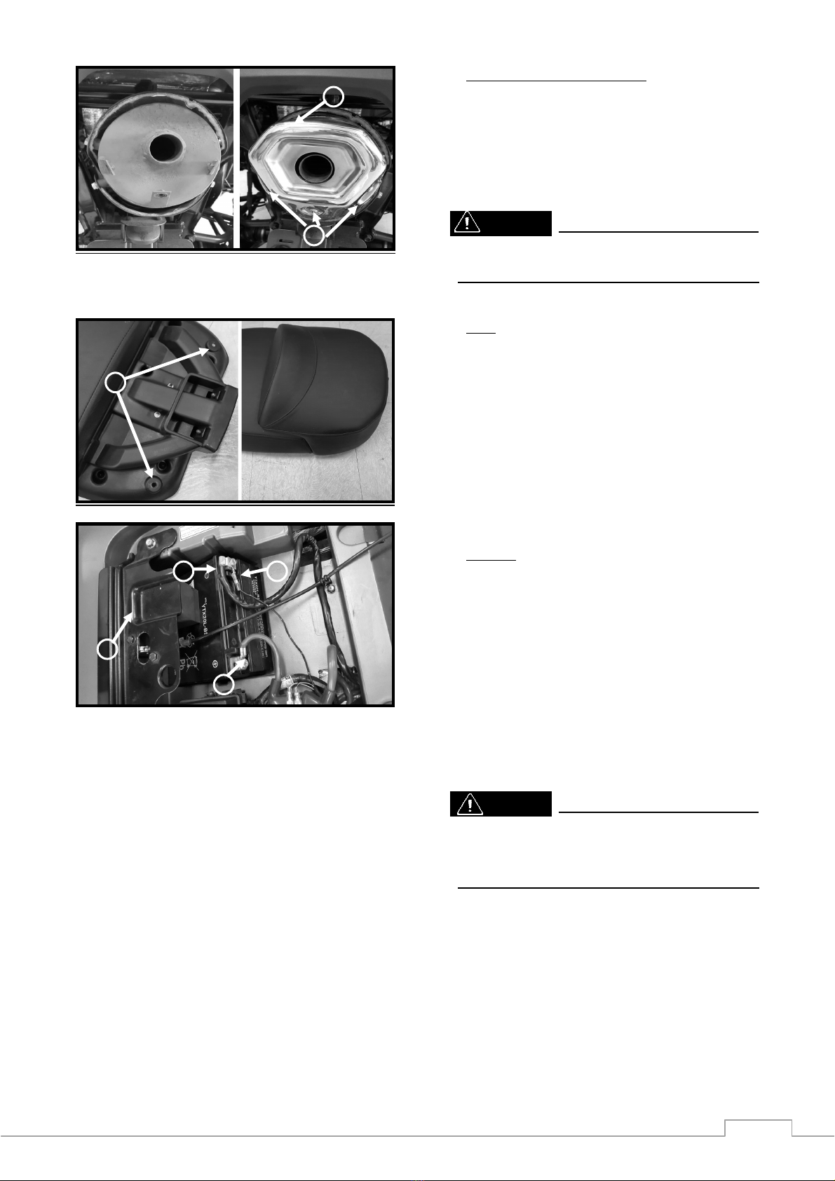
11. Muffler Ornamental Cover
The ornamental cover (A) with slight
adjustable ability, please adjust to the
correct position to cover the s ew deviation.
And then tighten the 3 (B) bolts.
Warning
Never operate while the muffler with high
temperature.
12. Seat
Ta e off the 2 nuts on the passenger seat
and then assemble to the mounting points
(A) on the main seat. Please carry out this
operation on a soft surface to avoid
damage to the seat leather.
13. Battery
Remove the battery mounting brac et (A)
and place the battery in the positioning,
ma e the positive (+) be on the left side of
the vehicle, and then re-tighten the brac et
to secure the battery. Connecting the red
cable (B) to positive (+), and then
connecting the two blac cables (C,D) to
negative (-).
Caution
Follow the preparation guide in the battery
pac age to ready the battery before
mounting to the vehicle.
B
A
B
A
B
C D
This manual suits for next models
1
Table of contents
Other TGB Offroad Vehicle manuals


