TGB EST 1000 User manual
EST1000
SERVICEMANUAL
TAIWANGOLDENBEE CO.,LTD.

Thisservice manualcontainsthetechnicaldataofeachcomponent
inspectionandrepairsfor the Blade1000.The manualis
shown withillustrations andfocusedon ServiceProcedures”,
OperationKeyPoints”,and InspectionAdjustment”sothatprovides
technicianwithservice guidelines.
If the styleandconstructionoftheBlade1000aredifferent
fromthatof thephotos,picturesshown inthismanual,theactual
vehicleshall prevail.Specificationsaresubjecttochangewithout
notice.
Thisservice manualdescribesbasicinformationof differentsystem
partsandsysteminspection&service forBlade1000.In
addition,please refertothemanualcontentsindetailedforthe
modelyouservicedininspectionandadjustment.
Please seethecontentforquick havingthe specialpartsandsystem
information.

1. GENERAL INFORMATION
1-2
PAGE
CONTENT
1
GENERALINFORMATION
2
SERVICEMAINTENANCEINFORMATION
3 LUBRICATIONSYSTEM
4-1
FUELSYSTEM
4-2
FUELINJECTIONSYSTEM
5-1
ENGINEASSEMBLY
5-2
ENGINETOPEND
5-3
ENGINEBOTTOM END
5
-
4
TRANSMISSIONBEARBOX
5
-
5
CONTINUOUSLY VARIABLETRANSMISSION
6 DRIVESYSTEM
7-1
STEERINGSYSTEM &SUSPENSION
7-2
ELECTRICPOWERSTEERING
7-3
BRAKESYSTEM &BODYCOVER
8-1
ELECTRICSYSTEM
8-2
ELECTRICDIAGRAM
1. GENERAL INFORMATION
1-3
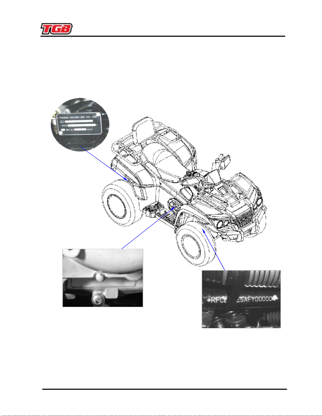
SERIALNUMBER
FrameNumberandEngineNumber
TST*000001*

2.MAINTENANCEINFORMATION
2
-
1
PrecautionsinOperation 2-1
PeriodicalMaintenanceSchedule 2-2
FuelLines 2-3
Acceleration Operation 2-3
AirCleaner 2-3
SparkPlug 2-3
ValveClearance 2-4
CarburetorIdleSpeedAdjustment 2-5
Ignition System 2-6
CylinderCompressionPressure 2-6
DriveBelt 2-7
BrakeSystem(DiskBrake) 2-8
BrakeLight Switch/StartingInhibitor
Switch 2-9
HeadlightBeamDistance 2-10
ClutchDiscWear 2-10
Cushion 2-10
SteeringHandle 2-11
Wheel/Tire 2-11
Nuts,BoltsTightness 2-11
SpecialTools List 2-12
Specification
Fuel Tank Capacity
2300c.c.
Oil &FilterChange
2000
c.c.
Oilchange
1800c.c.
EngineOil
NewEngine
2300c.c.
BearBox Capacity
900cc
Front Capacity
350
c.c.
TransmissionGearoil
Rear Capacity
500
c.c.
Engine +Radiator
2600c.c.
Capacity of coolant
Reservoirupper
1100c.c.
Clearanceof throttlevalve
1~3mm
Type
NGKDCPR8E
Spark Plug Gap
0.7~0.8
mm
Idling speed
1250±100 rpm
Cylindercompression pressure
9 ±1kgf/cm²
Valveclearance
IN:0.10 ±0.02mm
EX:0.15 ±0.02
mm
Front
AT25x8-12 AT26x8-14
Tiredimension
Rear
AT25x10-12 AT26x10-14
Tirepressure
7psi
Battery
12V18Ah(type: MFbattery)
PDFcreated withpdfFactoryProtrialversion www.pdffactory.com
Table of contents
Other TGB Offroad Vehicle manuals


