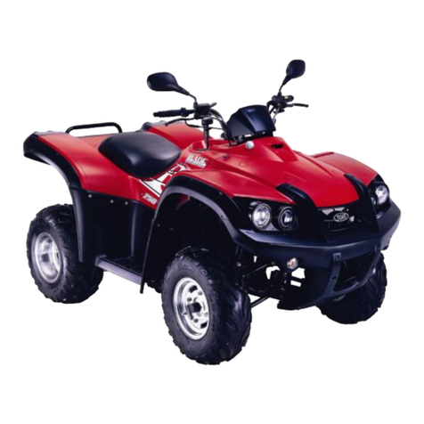
TGB BLADE 425 User manual

BLADE425/400
SERVICE MANUAL

Homepag
e
Contents
FORWARD
Thisservicemanualcontainsthetechnicaldataofeachcomponent inspectionand
repair for the
BLADE
425/400ATV.Themanualisshownwithillustrations
andfocusedon ServiceProcedures”, OperationKeyPoints”,and Inspection
Adjustment”sothatprovidestechnicianwithserviceguidelines.
If thestyleandconstructionof theATV,
BLADE
425/400,aredifferent from that
of thephotos,picturesshowninthismanual, theactualvehicleshall prevail.
Specificationsaresubject tochangewithoutnotice.
Service Department
TAIWANGOLDENBEE CO., LTD.

HomepageContents
HOWTOUSETHIS MANUAL
Thisservicemanualdescribesbasicinformationofdifferentsystempartsand
system inspection&servicefor
BLADE
425/400ATV.
Inaddition,
pleaserefer tothemanualcontentsindetailedfor themodelyouservicedin
inspectionandadjustment.
Thefirstchaptercoversgeneralinformationandtroublediagnosis.
Thesecondchaptercoversservicemaintenanceinformationandspecialtools
manual.
The third tothe 11thchapterscoverengine anddrivingsystems.
The 12thchapter iscooling system.
The 13thtothe16thchapteriscontained the partssetofassemblyframebody.
The 17thchapter iselectricalequipment.
The 18thchapter iswiringdiagram.
Pleaseseeindexof content forquickhavingthespecialpartsandsystem
information.

Homepage
CONTENTS
PageContentIndex
1-1~1-18
GENERALINFORMATION
1
2-1~2-14
SERVICE MAINTENANCE INFORMATION
2
3-1~3-7
LUBRICATIONSYSTEM
3
4-1~4-12
FUELSYSTEM
4
5-1~5-14
ENGINE REMOVAL
5
6-1~6-16
CYLINDER HEAD/VALVE
6
7-1~7-8
CYLINDER/PISTON
7
8-1~8-14
V”TYPE BELTDRIVING SYSTEM/KICK-STARTER
8
9-1~9-11
FINALDRIVING MECHANISM
9
10-1~10-10
ALTERNATOR/STARTINGCLUTCH
10
11-1~11-20
CRANKSHAFT/ CRANKCASE
11
12-1~12-11
COOLING SYSTEM
12
13-1~13-9
BODY COVER
13
14-1~14-14
FRONTBRAKE AND FRONTWHEEL
14
15-1~15-10
STEERING/FRONTSUSPENSION
15
16-1~16-15
REAR BRAKE/REAR WHEEL/REAR CUSHION
16
17-1~17-22
ELECTRICALEQUIPMENT
17
18-1~18-2
ELECTRICALDIAGRAM
18

SERIALNUMBER Homepage Contents
Framenumber
Enginenumber

HomepageContents
1. GENERALINFORMATION
SymbolsandMarks............................. 1-1
General Safety..................................... 1-2
ServicePrecautions............................ 1-3
Specifications...................................... 1-9
Symbolsand Marks
TorqueValues .................................... 1-10
1
Troubles Diagnosis............................1-12
LubricationPoints............................. 1-17
Symbolsand marksareusedinthismanualtoindicatewhat andwherethe specialserviceareneeded,in
casesupplementalinformationisproceduresneeded
forthesesymbolsand marks, explanationswillbe
addedtothe text insteadofusingthe symbolsormarks.
Warning
Meansthatseriousinjuryoreven deathmayresult ifproceduresarenot
followed.
Caution
Meansthatequipmentdamagesmayresult ifproceduresarenotfollowed.
Engine
oil
LimitstouseSAE10W-40 APISGclass oil.
Warrantywill notcoverthe
damage thatcausedbynot applywiththelimitedengineoil.
Grease
KingMateG-3isrecommended.
Locking
sealant
Applysealant;mediumstrengthsealantshouldbeused unlessotherwise
specified.
Oil
seal
Applywithlubricant.
Renew
Replacewithanewpartbeforeinstallation.
Brake
fluid
Userecommended brakefluidDOT4orWELLRUNbrakefluid.
Special
tools
Specialtools
Correct
Meaningcorrectinstallation.
Wrong
Meaningwrong installation.
Indication
Indicationofcomponents.
Directions
Indicatesposition andoperationdirections
Componentsassemblydirectionseachother.
Indicateswherethe boltinstallation direction,---meansthatbolt
crossthroughthe component(invisibility)
1-1

To thischaptercontents
1. GENERALINFORMATION
GeneralSafety
Carbonmonoxide
If youmust runyourengine,ensurethe placeis
wellventilated.Neverrun yourengine inaclosed
area. Runyourengineinan openarea,ifyouhave
torunyourengine inaclosed area,be suretouse
anextractor.
Caution
Exhaustcontainstoxicgaswhichmaycauseone
toloseconsciousnessandeven resultindeath.
Gasoline
Gasolineisalowignition pointand explosive
material.Workinawell-ventilated place, noflame
orsparkshouldbeallowed inthe workplaceor
wheregasolineisbeingstored.
Caution
Gasolineishighlyflammable,and mayexplode
undersomeconditions,keep itawayfrom
children.
Usedengineoil
Caution
Prolonged contact withused engine oil (or
transmissionoil)maycauseskincanceralthoughit
mightnot beverified.
Werecommend thatyouwashyourhandswith
soap and waterrightaftercontacting.Keepthe
used oil beyondreachofchildren.
Hotcomponents
Caution
Componentsoftheengineand exhaust system
can becomeextremelyhotafterenginerunning.
Theyremainveryhotevenaftertheenginehas
beenstoppedforsometime. Whenperforming
serviceworkontheseparts, wearinsulated
glovesandwaituntil cooling off.
Battery
Caution
•
Batteryemitsexplosivegases;flameisstrictly
prohibited. Keepstheplacewell ventilated
when chargingthe battery.
•
Batterycontainssulfuricacid(electrolyte)
whichcan causeseriousburnssobe careful
donotbesprayon youreyesorskin.If you
get batteryacidonyourskin,flushit off
immediatelywithwater.Ifyougetbatteryacid
inyoureyes,flushit offimmediatelywithwater
andthengotohospitaltosee an
ophthalmologist.
•
If youswallowitbymistake, drinkalotof
waterormilk,andtakesomelaxativesuchas
castoroilorvegetableoil and thengo toseea
doctor.
•
Keepelectrolytebeyondreachofchildren.
Brake shoe
Donot usean airhoseoradrybrushtoclean
componentsofthebrakesystem; useavacuum
cleanerorthe equivalenttoavoiddustflying.
Caution
Inhalingbrakeshoe orpadashmaycause
disordersandcancerofthe breathingsystem
Brake fluid
Caution
Spillingbrakefluidon painted,plastic,orrubber
partsmaycausedamage totheparts.Placea
clean towelonthe above-mentioned partsfor
protectionwhen servicingthebrakesystem.
Keepthebrakefluidbeyond reachofchildren.
1-2

To thischaptercontents
1. GENERALINFORMATION
Service Precautions
●
AlwaysusewithTGBgenuinepartsand
recommended oils.Using non-designed partsfor
TGB ATV maydamage the ATV.
●
Specialtoolsaredesignedforremoveand
install ofcomponentswithoutdamagingthe
partsbeingworkedon.Usingwrong toolsmay
result inpartsdamaged.
●
When servicingthisATV,useonlymetrictools.
Metricbolts,nuts, andscrewsarenot
interchangeablewiththeEnglishsystem, using
wrong toolsandfastenersmaydamagethis
vehicle.
●
Clean the outside ofthepartsorthecoverbefore
removing itfromthe ATV. Otherwise,dirtand
depositaccumulated onthe part'ssurfacemayfall
intothe engine, chassis,orbrakesystemtocause
damage.
●
Washandcleanpartswithhigh ignitionpoint
solvent, andblowdrywithcompressedair.Pay
specialattentiontoO-ringsoroil sealsbecause
mostcleaningagentshaveanadverseeffecton
them.
●
Neverbendortwist acontrolcabletoprevent
unsmoothcontroland prematurewornout.
●
Rubberpartsmaybecomedeteriorated whenold,
and
prone tobedamaged bysolvent andoil.
Checkthesepartsbeforeinstallation tomakesure
thattheyareingoodcondition, replaceif
necessary.
●
When looseningacomponent whichhas
differentsized fasteners, operatewitha
diagonalpatternandworkfrominsideout.
Loosen thesmall fastenersfirst.Ifthe bigger
onesareloosenfirst,smallfastenersmay
receivetoomuchstress.
●
Storecomplexcomponentssuchas
transmissionpartsintheproperassembleorder
andtiethemtogetherwithawireforeaseof
installationlater.
●
Notethereassemblepositionofthe important
componentsbeforedisassembling themto
ensuretheywill be reassembled incorrect
dimensions(depth,distanceorposition).
●
Componentsnottobe reusedshouldbe
replacedwhen disassembled includinggaskets
metalsealrings, O-rings, oil seals,snaprings,
andsplitpins.
1-3

To thischaptercontents
1. GENERALINFORMATION
●
The lengthofboltsand screwsforassemblies,
coverplatesorboxesisdifferentfromoneanother,
besuretheyarecorrectlyinstalled.Incaseof
confusion,Inserttheboltintotheholetocompare
itslengthwithotherbolts, if itslengthoutside the
holeisthe samewithotherbolts, it isacorrect
bolt.Boltsforthesameassemblyshouldhavethe
samelength.
●
Tightenassemblieswithdifferentdimension
fastenersasfollows: Tighten all the fasteners
withfingers,thentightenthebigoneswith
specialtoolfirstdiagonallyfrominsidetoward
outside, importantcomponentsshouldbe
tightened2to3timeswithappropriate
incrementstoavoidwarpunlessotherwise
indicated.Boltsand fastenersshouldbekept
clean and dry.Donot applyoiltothethreads.
●
When oil sealisinstalled,fillthegroovewith
grease, install the oil sealwiththe nameofthe
manufacturerfacing outside,andcheckthe shaft
onwhichtheoil sealistobeinstalledfor
smoothnessandforburrsthatmaydamage the
oil seal.
●
Removeresiduesoftheoldgasketorsealant
beforereinstallation,grind withagrindstone if
the contactsurfacehasanydamage.
●
The endsofrubberhoses(forfuel,vacuum,or
coolant)shouldbe pushedasfarastheycan go
totheirconnectionssothatthereisenough room
belowtheenlargedendsfortightening the
clamps.
Groove
Clamp
Connector
●
Rubberand plasticbootsshouldbe properly
reinstalled tothe originalcorrectpositionsas
designed.
Boots
●
The toolshouldbepressedagainsttwo(inner
andouter) bearing raceswhen removingaball
bearing.Damage mayresultifthetoolispressed
againstonlyonerace(eitherinnerraceorouter
race).Inthiscase,the bearing shouldbe
replaced. Toavoiddamaging thebearing, use
equalforceon bothraces.
Manufacturer'sname
1-4
Bothofthese examplescanresultin
bearing damage.

To thischaptercontents
1. GENERALINFORMATION
●
Lubricatetherotationfacewithspecified
lubricantonthelubricationpointsbefore
assembling.
●
Checkifpositionsandoperation forinstalled
partsisincorrect andproperly.
●
Makesureservicesafetyeachotherwhen
conductingbytwopersons.
●
Notethat donotletpartsfall down.
●
Afterservicecompleted, makesureall
connectionpointsissecured.
Batterypositive(+)cableshouldbeconnected
firstly.
●
Andthetwopostsof batteryhavetobegreased
afterconnected thecables.
●
Makesurethatthebatterypostcapsare
locatedinproperlyafterthe batterypostshad
beenserviced.
●
Iffuseburned, ithastofindoutthecauseand
solvedit.
Andthenreplacewithspecified
capacityfuse.
●
Beforebatteryremovaloperation, it hasto
removethe batterynegative(-)cablefirstly. Notre
toolslikeopen-end wrenchdonotcontact with
bodytopreventfromcircuitshortand create
spark.
Capacity
verification
1-5

To thischapterc
ontents
1. GENERALINFORMATION
●
When separatingaconnector,it lockerhastobe
unlocked firstly.
Then,conducttheservice
operation.
●
Donot pullthe wiresasremovingaconnector
orwires.
Holdtheconnectorbody.
●
Makesureifthe connectorpinsarebent,
extrudedorloosen.
●
Insertthe connectorcompletely.
If therearetwolockersontwoconnectorsides,
makesurethe lockersarelockedinproperly.
Checkifanywireloose.
●
Checkiftheconnectoriscoveredbythetwin
connectorboot completelyandsecured
properly.
●
Beforeterminalconnection,checkifthe boot is
crackorthe terminalisloose.
1-6
●
Insertthe terminalcompletely.
Checkiftheterminaliscovered bytheboot.
Donotletbootopenfacingup.
●
Securewiresandwireharnessestothe frame
withrespectivewirebandsatthe designated
locations. Tighten the bandssothatonlythe
insulated surfacescontactthe wiresorwire
harnesses.
●
Wirebandandwireharnesshavetobe
clamped secured properly.
●
Donotsqueezewiresagainstthe weldorits
clamp.

To thischaptercontents
1. GENERALINFORMATION
●
Donotletthewireharnesscontact withrotating,
movingorvibratingcomponentsasroutingthe
harness.
●
Keepwireharnessesfarawayfromthehot
parts.
NeverTouch
●
Routewireharnessestoavoidsharpedgesor
cornersandalsoavoidtheprojectedendsof
boltsandscrews.
●
Routeharnessessothattheyneitherpulltoo
tightnorhaveexcessiveslack.
●
Protect wiresorwireharnesseswithelectrical
tape ortube iftheycontact asharpedgeor
corner.Thoroughlycleanthesurfacewhere
tape istobe applied.
●
Securetherubberbootfirmlyasapplyingit on
wireharness.
●
Neverusewiresorharnesseswhichinsulation
hasbeenbroken.
Wrapelectricaltapearound
the damagedpartsorreplacethem.
●
Neverclamporsqueezethewireharnessas
installing othercomponents.
Neverclampor
squeezethewire
harness
Nevertootight
1-7

To thischaptercontents
1. GENERALINFORMATION
●
Donotletthewireharnessbeentwistedas
installation.
●
Wireharnessesrouted along the handlebar
shouldnotbe pulled tootight orhaveexcessive
slack,berubbedagainstorinterferewithadjacent
orsurrounding partsinall steeringpositions.
●
Beforeoperatingatest instrument, operator
shouldread the operationmanualofthe
instrument.Andthen,conducttestin
accordancewiththeinstruction.
●
Withsand papertoclean ruston connector
pins/terminalsiffound.
Andthen conduct
connectionoperation later.
Cleanrust
Doyou knowhowtosetthe
instrumenttoits
measurementpositionand
theinsertlocationsofits
twoprobes?
1-8

To thischaptercontents
1. GENERALINFORMATION
Specifications
MAKER
TGB
MODEL
FBE
Overall Length 2290 mm FrontDoublearm
Overall Width 1154 mm
Suspension
System Rear Unit Swing
Overall Height 1242 mm Front185/88-12
WheelBase 1268 mm
Tire
Specifications Rear 270/60-12
Front940mm Rim Aluminum
Wheeltread
Rear 890mm Front
Disk(Ø180mm)
Front170kg BrakeSystem Rear
Disk
(Ø200mm)
Rear 145kg Max.SpeedAbove92km/hr
Curb
Weight Total315kg Performance
ClimbAbility
Below25゚
Passengers/weightTwo/ 150kg
Front205kg
Primary
Reduction Belt
Rear 280kg
Weight Dimension
Total
Weight Total485kg
Secondary
Reduction Gear/ Shaft
Type 4-StrokeEngine Clutch Centrifugal, drytype
Installationand
arrangement Vertical,below
center, incline
Reduction
Transmission C.V.T.,autospeed
change
FuelUsed Above92unleaded Speedometer 0~ 300km/hr
Cycle/Cooling 4-stroke/Watercooled
Horn 93 ~ 112dB/A
Bore
Ø86
mm
Muffler
Expansion &Pulse
Type
Stroke
69.4
mm
ExhaustPipe Position
andDirection
Leftside,and
Backward
Cylinder
Number/
Arrangement
SingleCylinder
Lubrication System
Forcedcirculation&
splashing
Displacement
403.1cc
SolidParticulate
Compression Ratio
9.2: 1
CO
Below7.0g/km
Max. HP
14.9kw/ 6500rpm
HC
Below1.5g/km
Max. Torque
25.5Nm/4000rpm
Exhaust
Concentration
Nox
Below0.4g/km
Ignition
C.D.I.
E.E.C.
StartingSystem
Electricalstarter
P.C.V.
Engine
Airfiltration
Sponge
Catalyticreactioncontrol
system
1-9

1. GENERALINFORMATION
Torque Values
The torquevalueslistedinabovetableareformoreimportanttighten torquevalues. Pleaseseestandard
valuesfornotlisted inthe table.
StandardTorqueValues forReference
Type
TightenTorque
Type
TightenTorque
5mmbolt
、
nut
0.45~0.6kgf-m
5mm screw
0.35~0.5kgf-m
6mmbolt
、
nut
0.8~1.2kgf-m
6mm screw
、
SHnut
0.7~1.1kgf-m
8mmbolt
、
nut
1.8~2.5kgf-m
6mmbolt
、
nut
1.0~1.4kgf-m
10mm bolt
、
nut
3.0~4.0kgf-m
8mmbolt
、
nut
2.4~3.0kgf-m
12mm bolt
、
nut
5.0~6.0kgf-m
10mm bolt
、
nut
3.5~4.5kgf-m
EngineTorqueValues
Item
Q’ty
ThreadDia. (mm)
TorqueValue(kgf-m)
Remarks
Cylinderstudbolt
4
10
1.0~1.4
Cylinderheadnut
4
8
3.6~4.0
Cylinderheadright bolt
2
8
2.0~2.4
Cylinderheadside coverbolt
2
6
1.0~1.4
Cylinderheadcoverbolt
4
6
1.0~1.4
Cylinderheadstudbolt(inlet pipe)
2
6
1.0~1.4
Cylinderheadstudbolt(EX. pipe)
2
8
2.4~3.0
Airinjectpipe bolt
4
6
1.0~1.4
Airinjectreed valvebolt
2
3
0.07~0.09
Tappetadjustmentscrewnut
4
5
0.7~1.1
Applyoil tothread
Sparkplug
1
10
1.0~1.2
Tensionerlifterbolt
2
6
1.0~1.4
Carburetorinsulatorbolt
2
6
0.7~1.1
Oil pumpscrew
2
3
0.1~0.3
Waterpumpimpeller
1
7
1.0~1.4
Engineleftcoverbolt
9
6
1.1~1.5
Engineoil drainingbolt
1
12
3.5~4.5
Engineoil strainercap
1
30
1.3~1.7
Missiondrainingbolt
1
8
1.1~1.5
Missionfillingbolt
1
12
3.5~4.5
Shiftdrumfixing bolt
1
14
3.5~4.5
Clutchdrivingplatenut
1
28
5.0~6.0
Clutchouternut
1
14
5.0~6.0
Drivefacenut
1
14
8.5~10.5
ACG. Flywheelnut
1
14
5.0~6.0
Crankcasebolts
7
6
0.8~1.2
Missioncasebolt
7
8
2.6~3.0
1-10

To thischaptercontents
1. GENERALINFORMATION
FrameTorqueValues
Item
Q’ty
ThreadDia. (mm)
TorqueValue(kgf-m)
Remarks
Handlebarupperholderbolt
4
6
2.40
Steeringshaftnut
1
10
5.00
Steeringtie-rod nut
4
10
5.00
Knucklenut
2
10
5.00
Steeringshaftholderbolt
2
8
3.40
Tierodlocknut
4
10
3.60
Handlebarunderholdernut
2
8
4.00
Frontwheelnut
8
10
2.40
Frontaxlecastlenut
2
14
5.00
Rearaxlecastlenut
2
14
5.00
Rearwheelnut
8
10
2.40
Engine hangernut
4
12
8.50
Rearaxleholderbolt
4
12
9.20
Drivegearbolt
2
10
4.6
Driven gearnut
4
10
4.6
Swingarmpivotbolt
1
14
9.20
Frontsuspensionarmnut
4
10
5.00
Front
/ Rearcushion mountingbolt
6
10
4.60
Brakelevernut
2
6
1.00
Brakehosebolt
13
10
3.50
Brakecaliperbolt
6
6
3.25
Brakediskmounting bolt
11
8
4.25
Air-bleed valve
3
5
0.50
Exhaust mufflermounting bolt
2
8
3.00
Exhaust mufflerconnectionnut
2
7
1.20
1-11

To thischaptercontents
1. GENERALINFORMATION
TroublesDiagnosis
A. Enginehardtostartorcannotbestarted
Checkandadjustment
Faultcondition
Probablecauses
Loosencarburetordrainboltto
check ifthereisgasolineinside
thecarburetor
Fuelsuppliedtom
carburetorsufficient
Removesparkplug, install it
intosparkplugcap,andperforma
sparktestagainst engineground.
Nofuelissupplied to
carburetor
Nofuelinfueltank
Check ifthepipes, fueltanktocarburetor
andintakevacuum, areclogged.
Float valveclogged
Linesinfueltankevaporation
systemclogged
Malfunction of fuelpump
Loosenordamaged fuelpump
vacuumhose
Fuelfilterclogged
Malfunction ofsparkplug
Sparkplugfoul
Checkif sparks Weaksparks,nosparkat
all
Performcylindercompression
pressuretest.
Malfunction ofCDI set
Malfunction ofACgenerator
Ignitioncoil isinopen orshort circuit
Ignitioncoil leadsopenorshortcircuit
Malfunction of mainswitch
Cylindercompression
pressurenormal
Re-startbyfollowingthestarting
procedures
Lowcompression
pressureornopressure
Pistonringseized
Malfunctionofcylindervalves
Worncylinderand pistonring
Cylindergasketleak
Sand holeincompressionparts
Noignition Therearesomesignsof
ignition;nutenginecan
notbestarted
Malfunction of throttlevalveoperation
Airsuckedintointakemanifold
Incorrect ignitiontiming
Removethesparkplug again
andcheckit.
DrysparkplugWetsparkplug
Fuellevelincarburetortoohigh
Malfunction of throttlevalveoperation
Throttlevalveopeningtoo wide
Removecarburetorafter30
minutesand connectahose
ontofuelrichcircuit. Then blow
thehosewithair
BlowinginnormalBlowingclogged
Malfunction ofautomaticby-starter
1-12

To thischapter
1. GENERALINFORMATION
B. Enginerunsluggish(Speeddoesnotpick up, lackofpower)
Check and adjustmentFaultcondition Probablecauses
.
Trygradualaccelerationand
check enginespeed
Enginespeedcanbe
increased.
Checkignition timing (Using
ignitionlamp)
Enginespeedcannot be
increased.
Aircleanerclogged
Poorfuelsupply
Linesinfueltankevaporation
systemclogged
Exhaustpipeclogged
Fuelnozzleclogged incarburetor.
Fuelnozzleclogged incarburetor.
Ignitiontiming correctIncorrectignition timing
Malfunction ofCDI
Malfunction ofACalternator
Checkcylindercompression
pressure(usingcompression
pressuregauge)
Compressionpressure
correct
Checkif carburetorjetis
clogged
Nocompressionpressure
Cylinder&pistonringwornout
Cylindergasket leaked
Sandholeincompressionparts
Valvedeterioration
Seized pistonring
Noclogged Clogged
Removeforeign
Removesparkplug
NofoulordiscolorationFouled anddiscoloration
Checkifengineoverheat
NormalEngineoverheat
Continuallydriveinacceleration
orhighspeed
NoknockKnock
Removedirt
Incorrectsparkplugheatrange
Pistonandcylinderwornout
Lean mixture
Poorfuelquality
Toomuchcarbondeposited
incombustionchamber
Ignitiontimingtooadvanced
Poorcircuiton thecoolingsystem
Toomuchcarbondeposited
incombustionchamber
Lean mixture
Poorfuelquality
Ignitiontimingtooadvanced
1-13
To thischaptercontents

1. GENERALINFORMATION
.
C. Enginerunssluggish(especiallyinlowspeedandidling)
Checkandadjustment
Faultcondition
Probablecauses
Checkignition timing (using
ignitionlamp)
NormalAbnormal
Incorrect ignitiontiming (malfunctionof
CDIorACalternator)
Adjust theairscrewof
carburetor
Good Poor
Airsuckedthroughcarburetor
gasket
Noairsucked Airsucked
Removesparkplug, install spark
plugintosparkplug capand
performsparktestagainst
engineground
Good sparkPoor
D. Enginerunssluggish(Highspeed)
Richmixture(loosen thescrew)
Leanmixture(tightenthescrew)
Poorheat insulationgasket
Carburetorlockloose
Poorintakegasket
PoorcarburetorO-ring
Vacuumhosecrack
Sparkplugfouled
Malfunction ofCDI
Malfunction ofACgenerator
Malfunction of ignitioncoil
Open orshortcircuit insparkplugleads
Malfunction of mainswitch
Checkandadjustment
Faultcondition
Probablecauses
Checkignition timing
NormalAbnormal
Malfunction ofCDI
Malfunction ofACalternator
Checkforfuelsupplyingsystem
inautomaticfuelcup
Good Abnormal
Insufficient fuelinfueltank
Fuelfilterclogged
Restrictedfueltankvent
Checkif carburetorclogged
Noclogged Clogged
Cleaning
1-14

To thischapter
contents
1. GENERALINFORMATION
.
E. Clutch, drivinganddrivingpulley
FAULT CONDITIONS
PROBABLECAUSES
Enginecanbestartedbut
motorcyclecannot bemoved.
Drivebelt wornoutordeformation
Rampplateof movabledrivefacedamaged
Drivingpulleyspring broken
Clutchweightsbroken
Driveslide-shaft geargroovebroken
Transmissiongeardamaged
Enginerunningandmisfireas
motorcycleinitialforwardmovingor
jumpingsuddenly(rearwheelrotating
asengineinrunning)
Clutchweightsspringbroken
Clutchouterstuckwithclutchweights
Connectionpartsinclutchandshaft wornout orburned
Poorinitialdriving(Poorclimbing
performance)
Drivebelt wornoutordeformation
Weight rollerwornout
Movabledrivefaceshaft wornout
Driven pulleyspringdeformation
Driven pulleyshaft wornout
Greased indrivebeltand driven face.
F. Poorhandling
FAULT CONDITIONS
PROBABLECAUSES
Steeringisheavy
Damagedsteeringbearing
Damagedsteeringshaft bushing
Onewheeliswobbling
Bent rim
Improperlyinstalled wheelhub
Excessivewheelbearing play
Bentswingarm
Bent frame
Swingarmpivotbushingexcessively
Worn
Vehiclepullstooneside
Bent tie-rod
Incorrect tie-rodadjustment
Reartieairpressureincorrect
Improperwheelalignment
Bent frame
1-15
To thischaptercon
This manual suits for next models
1
Table of contents
Other TGB Offroad Vehicle manuals

