TGB Blade 525 User manual

BLADE500/525
SERVICEMANUAL
TAIWANGOLDENBEE CO.,LTD.
PDFcreated withpdfFactoryProtrialversion www.pdffactory.com

Homepag
e
Contents
FORWARD
This service manual contains the technicaldata of each component inspection and
repair for the
BLADE
525/500 ATV.The manual is shown with illustrations
and focused on Service Procedures”, Operation Key Points”, and Inspection
Adjustment”sothat provides technician with service guidelines.
If the style and construction of the ATV,
BLADE
525/500, are different from that
of the photos, picturesshown in thismanual, the actual vehicleshallprevail.
Specifications are subject tochange without notice.
ServiceDepartment
TAIWAN GOLDENBEECO.,LTD.
PDFcreated withpdfFactoryProtrialversion www.pdffactory.com

Homepage Contents
HOW TOUSE THISMANUAL
This service manual describes basic information of different system parts and
systeminspection & service for
BLADE
525/500 ATV. In addition,
please refer tothe manual contents in detailed for the modelyou serviced in
inspection and adjustment.
The first chapter covers general information and trouble diagnosis.
The secondchapter covers service maintenance information and specialtools
manual.
The third tothe 11thchapterscoverengineand driving systems.
The 12thchapter iscooling system.
The 13thto the16thchapter iscontained thepartsset of assembly framebody.
The 17thchapter iselectrical equipment.
The 18thchapter iswiring diagram.
Please see index ofcontent for quickhavingthe specialpartsand system
information.
PDFcreated withpdfFactoryProtrialversion www.pdffactory.com

Homepage
CONTENTS
PageContent Index
1-1~1-18
GENERALINFORMATION
1
2-1~2-14
SERVICEMAINTENANCEINFORMATION
2
3-1~3-7
LUBRICATIONSYSTEM
3
4-1~4-12
FUELSYSTEM
4
5-1~5-14
ENGINEREMOVAL
5
6-1~6-16
CYLINDER HEAD/VALVE
6
7-1~7-8
CYLINDER/PISTON
7
8-1~8-14
V”TYPE BELTDRIVINGSYSTEM/KICK-STARTER
8
9-1~9-11
FINALDRIVINGMECHANISM
9
10-1~ 10-10
ALTERNATOR/STARTING CLUTCH
10
11-1~ 11-20
CRANKSHAFT/ CRANKCASE
11
12-1~ 12-11
COOLINGSYSTEM
12
13-1~ 13-9
BODYCOVER
13
14-1~ 14-14
FRONTBRAKEAND FRONTWHEEL
14
15-1~ 15-10
STEERING/FRONTSUSPENSION
15
16-1~ 16-15
REARBRAKE/REARWHEEL/REAR CUSHION
16
17-1~ 17-22
ELECTRICALEQUIPMENT
17
18-1~ 18-2
ELECTRICALDIAGRAM
18
PDFcreated withpdfFactoryProtrialversion www.pdffactory.com

SERIAL NUMBER Homepage Contents
Framenumber
Enginenumber
PDFcreated withpdfFactoryProtrialversion www.pdffactory.com

Homepage Contents
1. GENERALINFORMATION
Symbolsand Marks............................. 1-1
GeneralSafety..................................... 1-2
Service Precautions............................ 1-3
Specifications...................................... 1-9
SymbolsandMarks
TorqueValues.................................... 1-10
1
TroublesDiagnosis............................ 1-12
Lubrication Points.............................1-17
Symbolsandmarks areused inthis manualtoindicatewhat and wherethespecialserviceareneeded,in
casesupplementalinformationisproceduresneeded
forthesesymbols andmarks,explanations will be
addedtothe textinsteadof usingthesymbols ormarks.
Warning
Meansthatseriousinjuryorevendeathmay resultifproceduresarenot
followed.
Caution
Meansthatequipment damages may resultifproceduresarenotfollowed.
Engine
oil
Limits touseSAE 10W-40API SGclass oil.
Warrantywillnotcoverthe
damagethat caused bynotapplywiththelimited engine oil.
Grease
KingMateG-3is recommended.
Locking
sealant
Apply sealant;mediumstrengthsealant shouldbeused unlessotherwise
specified.
Oil
seal
Apply withlubricant.
Renew
Replacewithanewpart beforeinstallation.
Brake
fluid
Userecommended brakefluidDOT4orWELLRUNbrakefluid.
Special
tools
Specialtools
Correct
Meaningcorrect installation.
Wrong
Meaningwronginstallation.
Indication
Indicationof components.
Directions
Indicatespositionand operation directions
Components assemblydirectionseachother.
Indicates wheretheboltinstallation direction, --- means thatbolt
cross through thecomponent (invisibility)
1-1
PDFcreated withpdfFactoryProtrialversion www.pdffactory.com

Tothischaptercontents
1. GENERAL INFORMATION
GeneralSafety
Carbonmonoxide
If you mustrun yourengine,ensurethe placeis
well ventilated.Neverrunyourengine inaclosed
area.Run yourengine inanopenarea,if you have
torun yourengineinaclosedarea,be suretouse
an extractor.
Caution
Exhaust contains toxicgaswhichmay causeone
toloseconsciousness and evenresultindeath.
Gasoline
Gasoline isalowignitionpointandexplosive
material.Workinawell-ventilatedplace,no flame
orspark shouldbeallowed inthework placeor
wheregasolineis being stored.
Caution
Gasolineis highlyflammable,and mayexplode
undersomeconditions, keepitawayfrom
children.
Usedengineoil
Caution
Prolonged contactwithusedengine oil(or
transmissionoil)may causeskincanceralthough it
mightnot beverified.
Werecommend thatyou washyourhandswith
soapand waterrightaftercontacting.Keepthe
usedoilbeyondreachof children.
Hotcomponents
Caution
Components oftheengineandexhaust system
can becomeextremelyhotafterengine running.
They remainveryhot evenafterthe engine has
beenstopped forsometime. Whenperforming
serviceworkontheseparts,wearinsulated
glovesandwait untilcooling off.
Battery
Caution
‧
Battery emits explosivegases; flameis strictly
prohibited.Keeps theplacewellventilated
whenchargingthebattery.
‧
Battery contains sulfuric acid(electrolyte)
whichcan causeseriousburnssobe careful
do notbe sprayon youreyesorskin.If you
get batteryacidon yourskin,flushit off
immediately withwater.If you get batteryacid
inyoureyes,flushit off immediatelywithwater
andthengo tohospitaltosee an
ophthalmologist.
‧
If you swallowitby mistake, drinkalot of
waterormilk,and takesomelaxativesuchas
castoroil orvegetableoiland then gotoseea
doctor.
‧
Keep electrolytebeyondreachof children.
Brakeshoe
Donotusean airhoseoradry brushtoclean
components ofthebrakesystem; useavacuum
cleanerorthe equivalent toavoiddust flying.
Caution
Inhalingbrakeshoeorpad ashmay cause
disordersandcancerofthebreathingsystem
Brakefluid
Caution
Spillingbrakefluidonpainted, plastic,orrubber
parts may causedamage totheparts. Placea
cleantowelon theabove-mentioned parts for
protectionwhen servicing thebrakesystem.
Keep thebrakefluidbeyondreachof children.
1-2
PDFcreated withpdfFactoryProtrialversion www.pdffactory.com

To thischaptercontents
1. GENERALINFORMATION
ServicePrecautions
●
Always usewithTGBgenuineparts and
recommendedoils.Usingnon-designedpartsfor
TGBATVmaydamage theATV.
●
Specialtools aredesignedforremoveand
installof componentswithout damagingthe
parts beingworked on.Using wrong toolsmay
result inparts damaged.
●
Whenservicing this ATV,useonlymetrictools.
Metricbolts,nuts,andscrewsarenot
interchangeablewiththeEnglishsystem, using
wrongtools and fasteners may damagethis
vehicle.
●
Cleanthe outsideof the parts orthecoverbefore
removing it fromthe ATV. Otherwise,dirtand
depositaccumulated onthe part'ssurfacemay fall
intothe engine, chassis,orbrakesystemtocause
damage.
●
Washand clean parts withhigh ignitionpoint
solvent,andblowdrywithcompressedair.Pay
specialattentiontoO-ringsoroilsealsbecause
most cleaning agentshavean adverseeffect on
them.
●
Neverbend ortwist acontrolcabletoprevent
unsmoothcontroland prematurewornout.
●
Rubberpartsmaybecomedeterioratedwhen old,
and
pronetobe damaged by solventandoil.
Check theseparts beforeinstallation tomakesure
that they areingood condition,replaceif
necessary.
●
When loosening acomponentwhichhas
different sized fasteners, operatewitha
diagonalpatternand work frominside out.
Loosen thesmallfastenersfirst.Ifthe bigger
onesareloosenfirst,smallfasteners may
receivetoomuchstress.
●
Storecomplex componentssuchas
transmissionparts intheproperassembleorder
and tiethemtogetherwithawireforeaseof
installation later.
●
Notethe reassemblepositionof theimportant
components beforedisassembling themto
ensuretheywillbereassembledincorrect
dimensions (depth, distanceorposition).
●
Components nottobereusedshouldbe
replacedwhen disassembled includinggaskets
metalsealrings, O-rings,oilseals, snap rings,
and splitpins.
1-3
PDFcreated withpdfFactoryProtrialversion www.pdffactory.com

Tothischaptercontents
1. GENERAL INFORMATION
●
Thelengthofboltsand screws forassemblies,
coverplates orboxes isdifferentfromoneanother,
be surethey arecorrectlyinstalled.Incaseof
confusion, Insertthebolt intothe holetocompare
its lengthwithotherbolts,if its lengthout sidethe
holeisthesamewithotherbolts, itis acorrect
bolt. Bolts forthesameassembly shouldhavethe
samelength.
●
Tightenassemblies withdifferentdimension
fastenersas follows: Tighten all the fasteners
withfingers, thentightenthe bigones with
specialtoolfirstdiagonally frominsidetoward
outside,important components shouldbe
tightened 2to3times withappropriate
increments toavoidwarpunlessotherwise
indicated. Boltsandfastenersshouldbe kept
cleanand dry. Donot apply oiltothe threads.
●
Whenoilsealis installed,fillthegroovewith
grease,installthe oilsealwiththenameof the
manufacturerfacing outside,andcheck theshaft
on whichtheoilsealistobe installedfor
smoothness and forburrs that may damage the
oilseal.
●
Removeresiduesofthe oldgasketorsealant
beforereinstallation,grind withagrindstoneif
thecontact surfacehas anydamage.
●
Theends of rubberhoses(forfuel, vacuum, or
coolant)shouldbepushed asfaras they can go
totheirconnections sothatthereis enough room
belowthe enlarged endsfortightening the
clamps.
Groove
Clamp
Connector
●
Rubberand plasticbootsshouldbe properly
reinstalledtotheoriginalcorrect positionsas
designed.
Boots
●
Thetoolshouldbe pressedagainst two(inner
and outer) bearing raceswhen removingaball
bearing. Damage may resultif thetoolispressed
against only onerace(eitherinnerraceorouter
race).Inthis case, the bearingshouldbe
replaced. Toavoiddamaging thebearing, use
equalforceonbothraces.
Manufacturer'sname
1-4
Bothoftheseexamplescanresultin
bearing damage.
PDFcreated withpdfFactoryProtrialversion www.pdffactory.com

To thischaptercontents
1. GENERALINFORMATION
●
Lubricatethe rotationfacewithspecified
lubricantonthelubricationpoints before
assembling.
●
Checkifpositionsand operation forinstalled
parts isincorrect and properly.
●
Makesureservicesafetyeachotherwhen
conducting by twopersons.
●
Notethat donotletparts fall down.
●
Afterservicecompleted, makesureall
connectionpoints is secured.
Battery positive(+)cableshouldbeconnected
firstly.
●
Andthe twoposts ofbattery havetobegreased
afterconnected thecables.
●
Makesurethat thebattery post capsare
located inproperlyafterthe battery posts had
beenserviced.
●
If fuseburned,it has tofindout thecauseand
solved it.
Andthenreplacewithspecified
capacity fuse.
●
Beforebattery removaloperation,it has to
removethebatterynegative(-)cablefirstly. Notre
toolslikeopen-endwrenchdo notcontact with
body topreventfromcircuitshortandcreate
spark.
Capacity
verification
1-5
PDFcreated withpdfFactoryProtrialversion www.pdffactory.com

To thischapterc
ontents
1. GENERAL INFORMATION
●
Whenseparating aconnector, itlockerhastobe
unlockedfirstly.
Then, conduct theservice
operation.
●
Donotpullthe wiresasremoving aconnector
orwires.
Holdthe connectorbody.
●
Makesureif the connectorpins arebent,
extrudedorloosen.
●
Insert the connectorcompletely.
If therearetwolockerson twoconnectorsides,
makesurethe lockersarelockedinproperly.
Checkifany wireloose.
●
Checkif the connectoriscoveredby thetwin
connectorboot completelyand secured
properly.
●
Beforeterminalconnection,check if the bootis
crackorthe terminalis loose.
1-6
●
Insertthe terminalcompletely.
Check if theterminaliscovered bythe boot.
Donot letboot openfacingup.
●
Securewiresandwireharnessestothe frame
withrespectivewirebands at thedesignated
locations. Tightenthe bands sothat onlythe
insulated surfaces contact the wiresorwire
harnesses.
●
Wirebandandwireharnesshavetobe
clampedsecured properly.
●
Donot squeezewiresagainsttheweldorits
clamp.
PDFcreated withpdfFactoryProtrialversion www.pdffactory.com

To thischaptercontents
1. GENERALINFORMATION
●
Donotletthewireharness contactwithrotating,
movingorvibrating components as routing the
harness.
●
Keep wireharnesses faraway fromthehot
parts.
NeverTouch
●
Routewireharnesses toavoidsharpedgesor
cornersandalsoavoidtheprojectedendsof
bolts and screws.
●
Routeharnesses sothattheyneitherpull too
tightnorhaveexcessiveslack.
●
Protect wiresorwireharnesseswithelectrical
tapeortubeiftheycontact asharpedgeor
corner.Thoroughly clean thesurfacewhere
tapeistobe applied.
●
Securethe rubberbootfirmlyas applyingit on
wireharness.
●
Neverusewiresorharnesseswhichinsulation
hasbeenbroken.
Wrapelectricaltapearound
thedamaged parts orreplacethem.
●
Neverclamporsqueezethewireharnessas
installingothercomponents.
Never clampor
squeeze thewire
harness
Never tootight
1-7
PDFcreated withpdfFactoryProtrialversion www.pdffactory.com

To thischaptercontents
1. GENERAL INFORMATION
●
Donotletthewireharnessbeentwistedas
installation.
●
Wireharnessesrouted along thehandlebar
shouldnot bepulled tootight orhaveexcessive
slack, be rubbed againstorinterferewithadjacent
orsurroundingparts inallsteering positions.
●
Beforeoperatingatest instrument,operator
shouldread theoperationmanualofthe
instrument.And then, conduct test in
accordancewiththe instruction.
●
Withsand papertoclean rust onconnector
pins/terminalsiffound.
Andthen conduct
connectionoperation later.
Cleanrust
Doyouknow howtosetthe
instrumenttoits
measurement position and
the insert locationsof its
twoprobes?
1-8
PDFcreated withpdfFactoryProtrialversion www.pdffactory.com
To thischaptercontents
1. GENERALINFORMATION
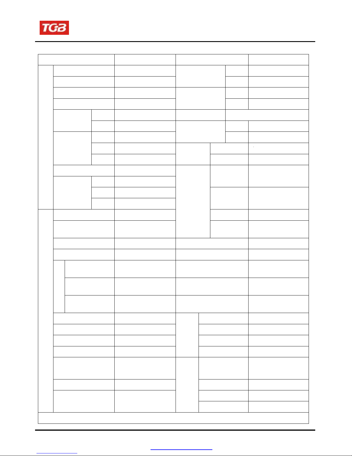
Specifications
MAKER
TGB
MODEL
FBG
Overall Length 2155mm Front Doublearm
Overall Width 1170mm
Suspension
System Rear UnitSwing
Overall Height 1205mm Front 25X8-12
WheelBase 1300mm
Tire
Specifications Rear 25X10-12
Front 930mm Rim Aluminum/ Steel
Wheeltread
Rear 940mm Front
Disk(Ø200mm)
Front 170kg BrakeSystem Rear
Disk
(Ø220mm)
Rear 145kg Max. Speed Above92 km/hr
Curb
Weight Total 315kg Performance
ClimbAbility
Below25゚
Passengers/weight Two/150 kg
Front 205kg
Primary
Reduction Belt
Rear 280kg
WeightDimension
Total
Weight Total 485kg
Secondary
Reduction Gear/ Shaft
Type 4-StrokeEngine Clutch Centrifugal,wettype
Installationand
arrangement Vertical,below
center,incline
Reduction
Transmission C.V.T.,autospeed
change
FuelUsed Above92 unleaded Speedometer 0~300 km/hr
Cycle/Cooling 4-stroke/Watercooled
Horn 93~112dB/A
Bore
Ø92
mm
Muffler
Expansion &Pulse
Type
Stroke
75.6
mm
ExhaustPipePosition
and Direction
Leftside,and
Backward
Cylinder
Number/
Arrangement
SingleCylinder
Lubrication System
Forcedcirculation&
splashing
Displacement
502.56cc
SolidParticulate
Compression Ratio
9.6
±
0.3
CO
Below7.0g/km
Max. HP
15.0kw /6500rpm
HC
Below1.5g/km
Max. Torque
26.6Nm/ 5000rpm
Exhaust
Concentration
Nox
Below0.4g/km
Ignition
C.D.I.
FrontLamps
(HI/LO)
12V55W×2
55W×2
StartingSystem
Electricalstarter
RearLamps 12V5W×1
BrakeLamps 12V21W×1
Engine
Airfiltration
Sponge
Lamps
TurnLamps 12V 10W
×
4
1-9
PDFcreated withpdfFactoryProtrialversion www.pdffactory.com

1. GENERAL INFORMATION
TorqueValues
Thetorque valueslistedinabovetableareformoreimportanttightentorque values. Pleasesee standard
valuesfornot listedinthetable.
StandardTorqueValues forReference
Type
TightenTorque
Type
TightenTorque
5mmbolt
nut
0.45~0.6kgf-m
5mm screw
0.35~0.5kgf-m
6mmbolt
nut
0.8~1.2kgf-m
6mm screw
SHnut
0.7~1.1kgf-m
8mmbolt
nut
1.8~2.5kgf-m
6mmbolt
nut
1.0~1.4kgf-m
10 mmbolt
nut
3.0~4.0kgf-m
8mmbolt
nut
2.4~3.0kgf-m
12 mmbolt
nut
5.0~6.0kgf-m
10mmbolt
nut
3.5~4.5kgf-m
EngineTorqueValues
Item
Q’ty
ThreadDia.(mm)
TorqueValue(kgf-m)
Remarks
Cylinderstud bolt
4
10
1.0~1.4
Cylinderheadnut
4
8
3.6~4.0
Cylinderheadright bolt
2
8
2.0~2.4
Cylinderheadsidecoverbolt
2
6
1.0~1.4
Cylinderheadcoverbolt
4
6
1.0~1.4
Cylinderheadstudbolt(inletpipe)
2
6
1.0~1.4
Cylinderheadstudbolt(EX.pipe)
2
8
2.4~3.0
Airinjectpipe bolt
4
6
1.0~1.4
Airinjectreedvalvebolt
2
3
0.07~0.09
Tappetadjustmentscrewnut
4
5
0.7~1.1
Apply oil tothread
Sparkplug
1
10
1.0~1.2
Tensionerlifterbolt
2
6
1.0~1.4
Carburetorinsulatorbolt
2
6
0.7~1.1
Oil pumpscrew
2
3
0.1~0.3
Waterpumpimpeller
1
7
1.0~1.4
Engineleftcoverbolt
9
6
1.1~1.5
Engineoildraining bolt
1
12
3.5~4.5
Engineoilstrainercap
1
30
1.3~1.7
Mission drainingbolt
1
8
1.1~1.5
Mission fillingbolt
1
12
3.5~4.5
Shiftdrumfixing bolt
1
14
3.5~4.5
Clutchdrivingplatenut
1
28
5.0~6.0
Clutchouternut
1
18
16~18
Drivefacenut
1
16
11.5~12
ACG. Flywheelnut
1
18
16~18
Crankcasebolts
7
6
0.8~1.2
Mission casebolt
7
8
2.6~3.0
1-10
PDFcreated withpdfFactoryProtrialversion www.pdffactory.com

To thischaptercontents
1. GENERALINFORMATION
FrameTorqueValues
Item
Q’ty
ThreadDia.(mm)
TorqueValue(kgf-m)
Remarks
Handlebarupperholderbolt
4
6
2.40
Steeringshaftnut
1
10
5.00
Steeringtie-rod nut
4
10
5.00
Knucklenut
2
10
5.00
Steeringshaftholderbolt
2
8
3.40
Tierodlocknut
4
10
3.60
Handlebarunderholdernut
2
8
4.00
Front wheelnut
8
10
2.40
Frontaxlecastlenut
2
14
5.00
Rearaxle castle nut
2
14
5.00
Rearwheel nut
8
10
2.40
Enginehangernut
4
12
8.50
Rearaxle holderbolt
4
12
9.20
Drivegearbolt
2
10
4.6
Driven gearnut
4
10
4.6
Swingarmpivotbolt
1
14
9.20
Frontsuspensionarmnut
4
10
5.00
Front
/ Rearcushion mountingbolt
6
10
4.60
Brakelevernut
2
6
1.00
Brakehosebolt
13
10
3.50
Brakecaliperbolt
6
6
3.25
Brakediskmountingbolt
11
8
4.25
Air-bleed valve
3
5
0.50
Exhaustmufflermountingbolt
2
8
3.00
Exhaustmufflerconnectionnut
2
7
1.20
1-11
PDFcreated withpdfFactoryProtrialversion www.pdffactory.com

To thischaptercontents
1. GENERAL INFORMATION
Troubles Diagnosis
A.Enginehardto startorcannot bestarted
Check andadjustment
Faultcondition
Probablecauses
Loosen carburetordrain bolt to
checkifthereisgasolineinside
thecarburetor
Fuelsupplied tom
carburetor sufficient
Removesparkplug, install it
into spark plugcap, and performa
sparktest against engineground.
Nofuel is supplied to
carburetor
No fuel in fueltank
Check ifthepipes,fuel tanktocarburetor
and intakevacuum,areclogged.
Float valve clogged
Lines infueltankevaporation
system clogged
Malfunctionof fuel pump
Loosen ordamagedfuel pump
vacuum hose
Fuelfilterclogged
Malfunctionof spark plug
Spark plug foul
Check if sparks Weak sparks, no sparkat
all
Performcylinder compression
pressure test.
Malfunctionof CDI set
Malfunctionof AC generator
Ignitioncoilis inopenor shortcircuit
Ignitioncoilleadsopenorshort circuit
Malfunctionof main switch
Cylinder compression
pressurenormal
Re-start byfollowing the starting
procedures
Lowcompression
pressureor no pressure
Piston ring seized
Malfunctionof cylindervalves
Worncylinderand piston ring
Cylindergasket leak
Sand hole in compressionparts
No ignition There aresomesigns of
ignition;nut engine can
notbestarted
Malfunctionof throttle valveoperation
Airsucked intointake manifold
Incorrect ignitiontiming
Remove thesparkplug again
andcheckit.
Dryspark plug Wet sparkplug
Fuellevelin carburetor too high
Malfunctionof throttle valveoperation
Throttlevalve openingtoowide
Remove carburetorafter30
minutesandconnect ahose
onto fuel rich circuit.Thenblow
thehosewithair
Blowing innormal Blowing clogged
Malfunctionof automatic by-starter
1-12
PDFcreated withpdfFactoryProtrialversion www.pdffactory.com

Tothischapter
1. GENERAL INFORMATION
B.Enginerun sluggish(Speeddoesnotpick up, lackofpower)
Checkandadjustment Faultcondition Probablecauses
.
Trygradualacceleration and
checkengine speed
Engine speedcan be
increased.
Check ignition timing (Using
ignitionlamp)
Engine speed cannot be
increased.
Air cleaner clogged
Poorfuel supply
Linesinfuel tankevaporation
system clogged
Exhaustpipeclogged
Fuelnozzle clogged in carburetor.
Fuelnozzle clogged in carburetor.
Ignitiontiming correct Incorrect ignitiontiming
Malfunctionof CDI
Malfunctionof AC alternator
Checkcylindercompression
pressure(usingcompression
pressuregauge)
Compressionpressure
correct
Check if carburetor jet is
clogged
No compressionpressure
Cylinder&piston ring worn out
Cylindergasket leaked
Sand hole in compressionparts
Valve deterioration
Seized piston ring
Noclogged Clogged
Removeforeign
Remove spark plug
Nofoulor discoloration Fouled and discoloration
Check if engine over heat
Normal Engine overheat
Continuallydriveinacceleration
orhighspeed
Noknock Knock
Remove dirt
Incorrect spark plug heatrange
Piston and cylinderworn out
Lean mixture
Poorfuel quality
Too muchcarbon deposited
in combustionchamber
Ignitiontiming too advanced
Poorcircuitonthecooling system
Too muchcarbon deposited
in combustionchamber
Lean mixture
Poorfuel quality
Ignitiontiming too advanced
1-13
To thischaptercontents
PDFcreated withpdfFactoryProtrialversion www.pdffactory.com

1. GENERAL INFORMATION
.
C.Enginerunssluggish(especiallyinlowspeedandidling)
Check and adjustment
Faultcondition
Probablecauses
Check ignition timing (using
ignitionlamp)
Normal Abnormal
Incorrect ignitiontiming (malfunction of
CDI orAC alternator)
Adjust the air screwof
carburetor
Good Poor
Air sucked through carburetor
gasket
Noair sucked Air sucked
Remove spark plug, installspark
plug into sparkplug cap and
perform sparktestagainst
engine ground
Good spark Poor
D.Enginerunssluggish(Highspeed)
Richmixture (loosenthescrew)
Lean mixture (tighten thescrew)
Poor heat insulationgasket
Carburetor lock loose
Poor intake gasket
Poorcarburetor O-ring
Vacuum hose crack
Spark plug fouled
Malfunctionof CDI
Malfunctionof AC generator
Malfunctionof ignitioncoil
Openor short circuit in spark plug leads
Malfunctionof main switch
Check andadjustment
Faultcondition
Probablecauses
Check ignition timing
Normal Abnormal
Malfunctionof CDI
Malfunctionof AC alternator
Check forfuel supplying system
in automatic fuelcup
Good Abnormal
Insufficient fuelinfueltank
Fuelfilterclogged
Restrictedfuel tankvent
Check if carburetor clogged
Noclogged Clogged
Cleaning
1-14
PDFcreated withpdfFactoryProtrialversion www.pdffactory.com

To thischapter
contents
1. GENERALINFORMATION
.
E. Clutch,driving anddriving pulley
FAULTCONDITIONS
PROBABLE CAUSES
Engine canbestarted but
motorcyclecannot be moved.
Drivebeltwornout or deformation
Ramp plateof movable driveface damaged
Driving pulleyspring broken
Clutchweights broken
Driveslide-shaftgear groovebroken
Transmission geardamaged
Engine running andmisfireas
motorcycle initialforwardmoving or
jumpingsuddenly(rearwheel rotating
as engineinrunning)
Clutchweights springbroken
Clutch outerstuckwithclutchweights
Connection parts inclutchand shaft wornoutorburned
Poorinitialdriving (Poor climbing
performance)
Drivebeltwornout or deformation
Weight roller wornout
Movable drivefaceshaft wornout
Drivenpulleyspring deformation
Drivenpulleyshaft wornout
Greasedindrive belt anddriven face.
F. Poorhandling
FAULTCONDITIONS
PROBABLE CAUSES
Steering isheavy
Damaged steering bearing
Damaged steering shaft bushing
One wheelis wobbling
Bent rim
Improperly installed wheelhub
Excessive wheel bearing play
Bent swing arm
Bent frame
Swing arm pivotbushing excessively
Worn
Vehicle pulls toone side
Bent tie-rod
Incorrect tie-rodadjustment
Reartieair pressure incorrect
Improperwheelalignment
Bent frame
1-15
To thischaptercon
PDFcreated withpdfFactoryProtrialversion www.pdffactory.com
Table of contents
Other TGB Offroad Vehicle manuals


