TGS WP-EWG-040U User manual
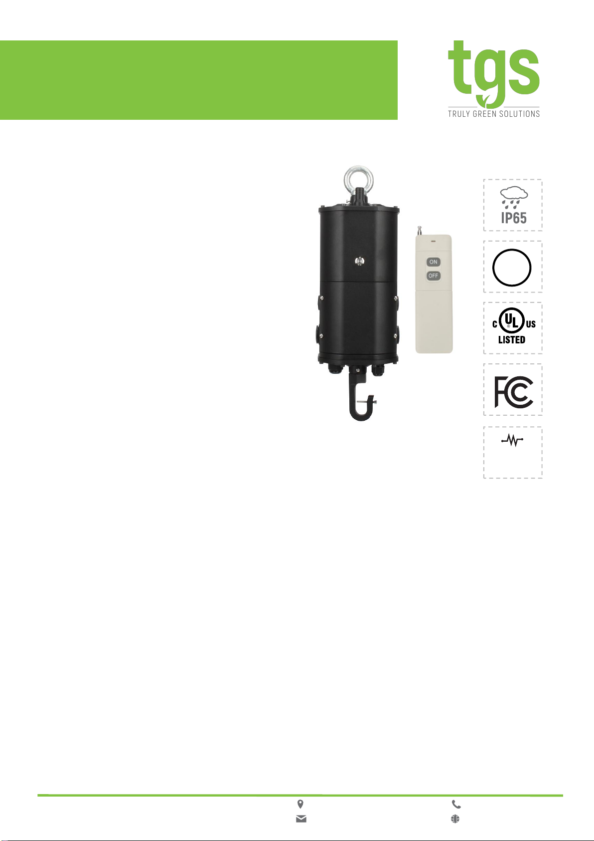
EMERGENCY INVERTER
WP-EWG-040U | for LED High Bay Lights
BC
Self
Diagnostic
General Description
The Emergency Inverter for LED High
Bay Lights, listed for field and factory
installation, provides constant power
output to the load during emergency
mode operation. They maintain
illumination in the emergency mode for
a minimum of 90 minutes. It is an ideal
emergency solution for Round/Circular
LED high bay fixtures.
Features and Benefits
• LiFePO4 safety batteries
• Link to the input of LED drivers
• High PF even during charging
• Safety rope prevent from dropping while
installation
• Remote test from a handheld controller
• Self-diagnostic every month and year
• RoHS compliant
• 5 years warranty
:9601 Variel Ave. Chatsworth, CA 91311
:info@trulygreensolu�ons.com
:818-206-4404
:www.trulygreensolu�ons.com
1
• Constant power output
• Universal input range
• Integrated junction box design
• Field and factory installation
• IP65 for dry, damp and wet location
• 40W & 90mins durable emergency
operating time
• Surge L-N:3KV; L&N-PE:3KV
• Protection: Over-Voltage ,Short-Circuit,
Over-Load, Open-Circuit

Ordering Information
Model Output Voltage Related Output Power Battery Capacity Emergency Time
WP-EWG-040U
120-200 Vdc
40 W
96 WH
90 mins
Input
Characteristics
Parameter
Min.
Typical
Max.
Remarks
Rated Input Voltage (Vac)
120
--
277
Input Voltage Range (Vac)
90
--
305
Input Frequency Range (Hz)
47
50/60
63
Max. Input Current(A)
--
--
0.2
120Vac, charging
Max. Input Power(W)
--
--
15
120Vac, charging
Input Surge Current(A)
--
--
10
277Vac/60Hz, cold start
Standby Power (W)
--
--
0.8
277Vac/60Hz, charged
Power Factor
0.9
--
--
Vin=120Vac/60Hz (charging)
THD
--
15%
20%
Vin=120-277Vac/60Hz
(charging)
Max. Load(W)
--
--
300
Min. dim power have to lower
than 36W
Output
Characteristics
Parameter
Min.
Typical
Max.
Remarks
No Load Output Voltage (Vac)
--
--
250
Emergency Output Power (W)
36
--
40
Constant power output
Instantaneous Output Power (W)
--
--
100
Emergency, cold start peak
output, last time 10 seconds
Power-up Time (S)
--
--
0.5
120Vac, charging
Response Time (S)
--
--
5
Switch from mains supply cuts
to Emergency output
Emergency Duration Time
90
--
--
Output Voltage (V)
120
--
200
approximate value, varies with
the battery voltage
Max. Load Current (mA)
--
--
350
Determined by the LED load,
load current=output power/
output voltage
:9601 Variel Ave. Chatsworth, CA 91311
:info@trulygreensolu�ons.com
:818-206-4404
:www.trulygreensolu�ons.com
2

Battery
Characteristics
Name
Parameter
Battery Type
LiFePO4
Battery Capacity
6000mAh/16V 96WH
Charging Time (H)
24 Hours
Max. Charging Interval (M)
12 Months
Environment Characteristics
Protection Characteristics
Parameter Status Min. Typica
lMax. Remarks
Over-Voltage Protection (V) ●-- -- 250
Short-Circuit Protection (mA) ●-- -- -- Power Off
Open-Circuit Protection (mA) ●-- -- -- Abnormal Indicator Light
Over-Load Protection (W)●-- -- 45 Power Off
Over-Temperature Protection (℃)x x x x
:9601 Variel Ave. Chatsworth, CA 91311
:info@trulygreensolu�ons.com
:818-206-4404
:www.trulygreensolu�ons.com
3
Parameter Min. Typical Max. Remarks
Work Temperature (℃)10 -- 50 Discharge time >=90mins
Work Humidity (RH) 10% -- 90%
Storage Temperature (℃) -20 -- 65
Storage Humidity (RH) 5% -- 95%
Altitude (m) -50 -- 3000
Cooling Method -- -- -- Air natural cooling

Other Characteristics
Parameter
Min.
Typical
Max.
Condition
Lifetime (H)
50000
--
--
MTBF (H)
--
200000
--
277Vac, Ta 25℃
(MIL-HDBK-217F)
Max. Installation Height (ft)
--
--
36
Weight (g)
3550
3700
3850
Dimension (Inch)
L4.92*W4.92*H11.22
Excluding the ring and hook
Remarks:
If not specified, all the above parameters are measured in the full load state of the product at Ta 25℃.
Safety Regulation
Certificate Approval
Marks Standard ValidRemarks
UL UL924North America
cUL CAN/CSA-C22.2 NO. 141Canada
BC BC CEC Title 20 California
:9601 Variel Ave. Chatsworth, CA 91311
:info@trulygreensolu�ons.com
:818-206-4404
:www.trulygreensolu�ons.com
4

Electromagnetic Compatibility
EMI/EMS Items
Standards
Judgement Basis
Conduction CE
FCC Part 15
Class B
Radiation RE
FCC Part 15
Class B
Harmonic Wave
IEC/EN 61000-3-2
Class C
Surge
UL924
L-N :3KV/2Ω,L&N-PE:3KV/2Ω
Ring-wave
ANSI C62.41
2.5KV/2Ω
Safety Test
Technical Requirements
Condition
Voltage
Withstand
Input-Ground
1500Vac/5mA/60S
No breakdown, no flashover
Output-Ground
1500Vac/5mA/60S
No breakdown, no flashover
Insulation Resistance
≥100Mohm
Input-Ground, Test Voltage 500Vdc
Leak Current
≤0.75mA
277Vac
Ground Resistance
≤0.1Ω
25A/1min
Remarks:
1. The power supply is considered as a component to be used in combination with the terminal equipment.
Because the Emergency Inverter is affected by the whole device, the terminal equipment manufacturer
shall confirm Emergency Inverter with the whole device.
2. During the voltage test, please short circuit the L-N, the positive and negative of output line, and the
positive and negative of dimming line
Safety Test Projects
Characteristic Curve
Peak Current (Ipk)
Time(t)
Time(T) 50% peak current (Ipk)
10% peak current (Ipk)
Input
Voltage
Ipk
Peak Current
T
(@10% Ipk)
T
(@50% Ipk)
120Vac
6A
700uS
500uS
277Vac
10A
400uS
200uS
Input Surge Current
:9601 Variel Ave. Chatsworth, CA 91311
:info@trulygreensolu�ons.com
:818-206-4404
:www.trulygreensolu�ons.com
5
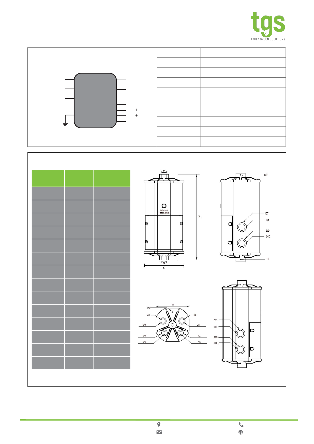
Structure
GND UL1015 18AWG Green 152mm
INPUT OUTPUT
AC-N UL1015 18AWG White 152mm
AC-L Un-Switch UL1015 18AWG Black 152mm
AC-N
AC-L Un-Switch
AC-L Wall Switch
AC-L Output
AC-L Wall Switch UL1015 18AWG White in Black 152mm
AC-N Output
LED AC-L Output UL1015 18AWG Blown 152mm
Emergency DIMMING
DIM Input AC-N Output UL1015 18AWG Blue 152mm
Driver DIM Input
GND DIM+ Input UL1015 18AWG Purple 152mm
DIM Output
DIM Output DIM- Input UL1015 18AWG Grey 152mm
DIM+ Output UL1015 18AWG Red 152mm
DIM- Output UL1015 18AWG Yellow 152mm
Name CodeSpec.
Length L 4.92 Inch
Width W 4.92 Inch
Height H 11.22 Inch
Fixed Hole D1 M12
Fixed Hole D2 G(PF) 1/2
Fixed Hole D3 1.26 Inch
Fixed Hole D4 0.87 Inch
Fixed Hole D5 G(PF) 1/4
Fixed Hole D6 6#-32*1/4
Fixed Hole D7 1.26 Inch
Fixed Hole D8 NPT 1/2
Fixed Hole D9 1.57 Inch
Fixed Hole D10NPT 3/4
Fixed Hole D116#-32* 5/8
:9601 Variel Ave. Chatsworth, CA 91311
:info@trulygreensolu�ons.com
:818-206-4404
:www.trulygreensolu�ons.com
6

Indicator
Diagnostic System
:9601 Variel Ave. Chatsworth, CA 91311
:info@trulygreensolu�ons.com
:818-206-4404
:www.trulygreensolu�ons.com
7
Parameter Remarks
Solid Green ON System OK/AC OK
None LED Off System NG, battery voltage is too low,
LED fixture is Short
Flashing Green (1s on, 1s off, cycling) Battery not detected, check battery connection
Flashing Green(0.1s on, 5s off, cycling) The Emergency inverter working in
Emergency mode
Discharge time is less than 90 minutes
(Self-diagnostic test), LED fixture is Open
Circuit, Over Load
Slow Flashing Green (5s on, 5s off, cycling)
Flashing Green (1s on, 1s off, 5 times) Disable Self-diagnostic test system
Flashing Green(1s on, 1s off, 3 times) Enable the Self-diagnostic test system
•Manual Diagnostic System
Under the normal charging mode, after the battery is charged for 12 hours or fully charged, long
press the test button for 3S and hold it, enter the manual test mode, release the button to exit the
manual diagnostic mode.
•Close / Start Self-diagnostic System
Under the Normal Charging Mode, press the button twice in two seconds, then press the button
longer than 2 sec. and less than 5 sec, then press the button twice in succession, the indicator light will be
on and off for 5 times (1 sec. interval), means disable the Self-Diagnostic Test System successfully. If you
want to enable the Self-Diagnostic Test System, repeat the operation, the indicator light will be on
and off for 3 times (1 sec. interval), means “Enable”.
•Enter Sleep Mode
Under Emergency Mode, press the test button 3 seconds, the Backup micro inverter will enter Sleep Mode
(Storage and transportation),and activate it by connecting to AC power.
•Reset
Under abnormal status, press and hold the test button >5 sec., power off, and re-connect to mains supply,
the System will be reset.
•Monthly Self-diagnostic
In the normal charging mode, the system performs a monthly self-diagnostic test every 30 days, the system
switches to the emergency mode for 30 sec., and automatically switches back to the normal
charging mode after 30 sec.
•Yearly Self-Diagnostic
In the normal charging mode, the system switches to the emergency mode every 360 days (after 11Monthly
self-diagnostic test) and works until the end of discharge. Automatically switches back to
normal charging mode after discharge.

Wiring Diagram
:9601 Variel Ave. Chatsworth, CA 91311
:info@trulygreensolu�ons.com
:818-206-4404
:www.trulygreensolu�ons.com

:9601 Variel Ave. Chatsworth, CA 91311
:info@trulygreensolu�ons.com
:818-206-4404
:www.trulygreensolu�ons.com
Wiring Diagram
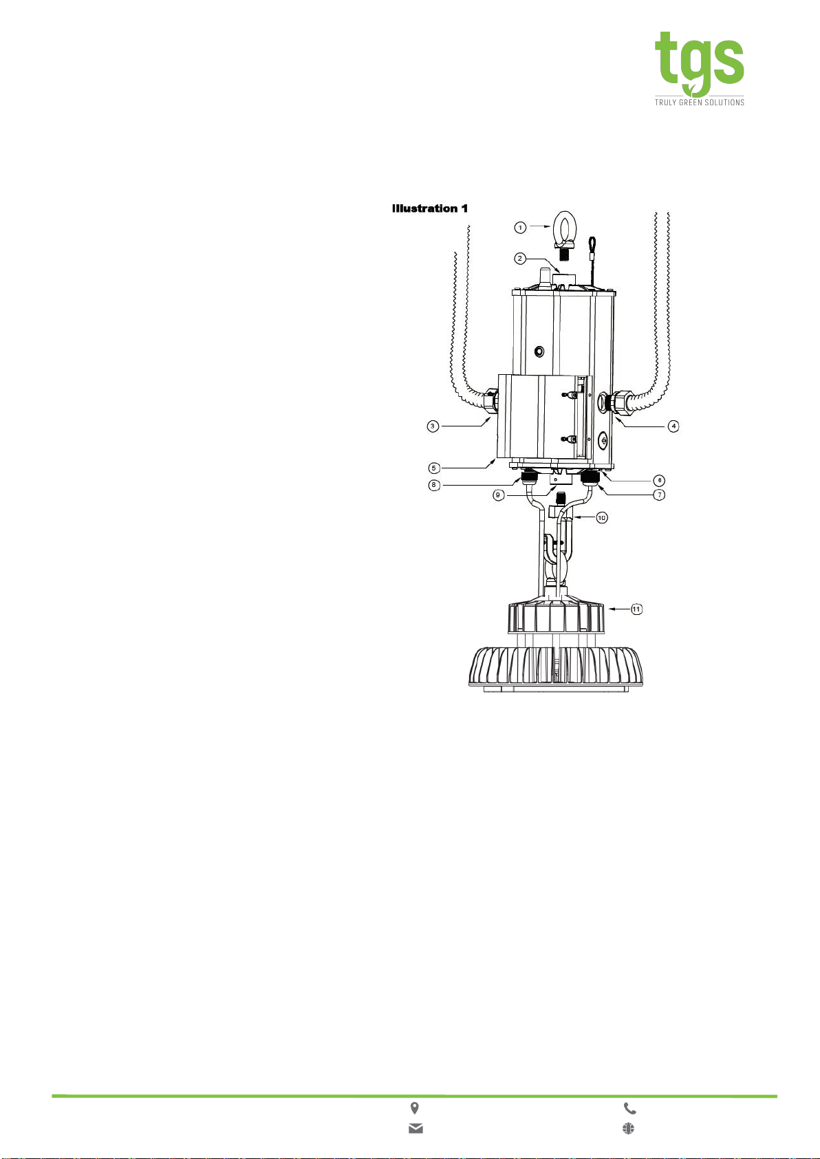
Installation Guideline
①Hanging ring bolt
②Thread mounted hole
③AC input wire protective tube
④Dimming wire protective tube
⑤Integrated junction box cover
⑥Safety rope
⑦LED Driver dimming wire
⑧LED Driver input wire
⑨Thread mounted hole
⑩Hanging hook bolt
⑪LED Driver of UFO highbay light
⑥
Attentions
Please use waterproof connectors in
position ③ and ④ for application in damp
location
:9601 Variel Ave. Chatsworth, CA 91311
:info@trulygreensolu�ons.com
:818-206-4404
:www.trulygreensolu�ons.com
8

Step One: Disconnect AC Power From Fixture
Disconnect all power source to the lighting fixture and ensure they are locked out during installation or
maintenance.
The AC driver must be source from the emergency inverter.
Select a suitable location for the emergency inverter an install such that its output leads can connect to the
input leads of the AC driver.
Step Two: Install The Emergency Inverter
Select a suitable location on the ceiling for the hangable device.
Install the ring bolt ①to the emergency inverters ②and fix it with screw.
Install the hook ⑩to the emergency inverter ⑨and fix it with screw.
Open the cover of the junction box ⑤.
Install the bushing ⑦(BN-M12-8 , Suitable for wire diameter 4-8mm, STYLE, SJTW, SJOW, SVT).
Install the bushing ⑧(BN-M12-8 , Suitable for wire diameter 4-8mm, STYLE, SJTW, SJOW, SVT).
Install the safety rope ⑥, the another end of the safety rope and ring bolt ①should fix together on the
fixing device on the ceiling.
Hang the emergency inverter to the hangable device on the ceiling.
Hang the LED lighting fixture ⑪to the hook of the emergency inverter.
Install the box cables on AC wires ③and dimming wires ④.
See Illustration 1, for typical installation and select appropriate mounting method.
NOTE:
1. Bushings are not installed on the emergency inverter at the factory, but packed in the kits bag.
2. Please use waterproof connectors in position ③ and ④ for application in wet location.
3. It is recommended to seal the dimming connector with an insulating sleeve, when the dimming function
is not necessary. To avoid the signal interfering with the dimming line, and cause damage to the power
supply.
4. Safety rope ⑥ is an optional component. If safety rope is not chosen then it is not needed for
installation.
5. Verify that the dimming wires of the luminaires and emergency inverter are connected properly,
Installation Guideline
:9601 Variel Ave. Chatsworth, CA 91311
:info@trulygreensolu�ons.com
:818-206-4404
:www.trulygreensolu�ons.com
9
Step Three: Wiring The Emergency Inverter
Use the wiring diagram located on page 5 as reference.
Connect the AC power source leads ( Switch and Un-Switch) to the input of the emergency inverter.
Connect the output leads of emergency inverter to the AC driver.
Wire the AC driver with the lamp in accordance with manufactures installation instructions.
Verify that all connections are in accordance with the National Electrical Code (NEC), Canadian Electrical
Code (CEC) and any local regulations.
Step Four: Lock Up The Cover Of Junction Box & Turn On Power
After installation is completed, turn on the power.
At this point, power sould be connected to both the AC driver and the emergency inverter, and the Charge
Indicator Light should illuminate indicating the battery is charging.
A short-term discharge test may be conducted after the emergency inverter has been chargin of 1 hour.
Charge for 24 hours before conducting a long-term discharge test.
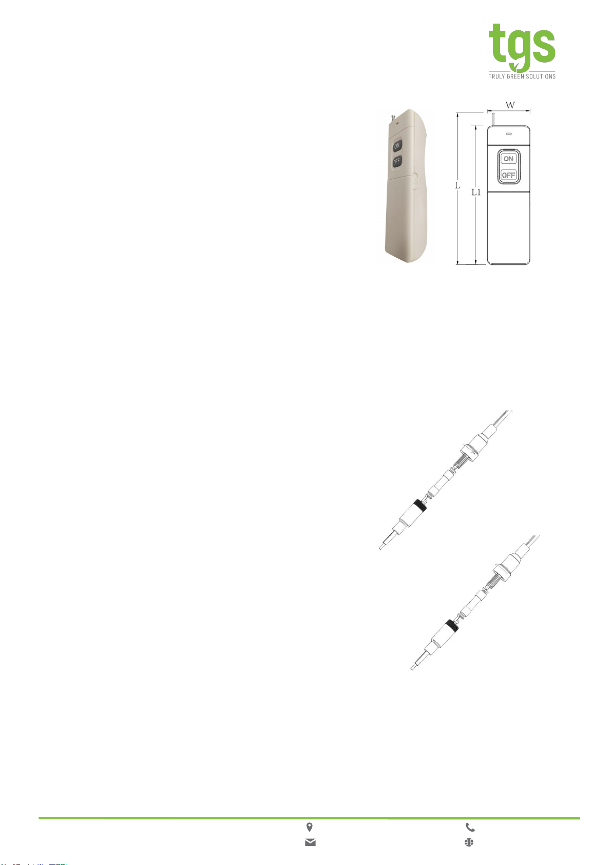
Remote Controller
Dimension(Inch)
L : 5.79
L1 : 5.35
W: 0.17
• Diagnosis
In the normal Charging Mode, after being charged
for 12 hours or fully charged, dial the switch on the
side(towards the antenna),pull out the antenna,
press the button ON, then it will enter Manual
Diagnostic Mode. Press OFF to exit.
• Controller Battery
6F22 9V aneroid battery or same specification
rechargeable battery.
• Remote Control Distance
No more than 20 meters, the received signal will be
better by pulling out the antenna.
Fuse Replacement
• Fuse Specifications
Time Lag Axial fuse(Glass Body or Ceramic Body)
Φ5 * 20mm, 10A/300V
• Purpose
To ensure the safety of products, the blown fuse
must be connected to the fixture live wire
(normal lighting switch control wire, black-into-white
wire). If short circuit occurs on luminaires, or
accidentally short-circuiting during wiring, that may
damage the fuse. Only operators with relevant
permits can open the fuse holder and replace it with
same specification fuse.
• Operation Method
Turn counterclockwise, open the fuse installation
box, take out the bad fuse, replace it with a new one,
and then turn clockwise to tighten.
Open: Counterclockwise
Close: clockwise
:9601 Variel Ave. Chatsworth, CA 91311
:info@trulygreensolu�ons.com
:818-206-4404
:www.trulygreensolu�ons.com
Light Output Calculation
To ensure sufficient light output in the end application, please estimate by doing the following:
a. Check the light efficacy(lm/w) of LED luminaire, which is provided by the luminaire manufacturer, test it
directly, check the test data from 3rd party test laboratory like UL, ETL etc., visit a 3rd party public
database (such as Design Lights Consortium, www.designlights.org etc.), or other comparable means.
b. Lumens can be calculated by multiplying the output power of the emergency inverter by the light efficacy
of the LED luminaire. In many cases, the actual lumen output in emergency mode will be greater than
what this calculation gives, however, it will provide a good reference for the lighting design.
c. Using the results of this calculation and industry standard lighting design tools, the expected illuminance
in the curve can be calculated.
Lumens In Emergency Mode = Lumens per Watt of Fixture * Output Power of Chosen Product
____________________(Lumens) = __________________(lm/W) * 40(W)
:9601 Variel Ave. Chatsworth, CA 91311
:info@trulygreensolu�ons.com
:818-206-4404
:www.trulygreensolu�ons.com
10
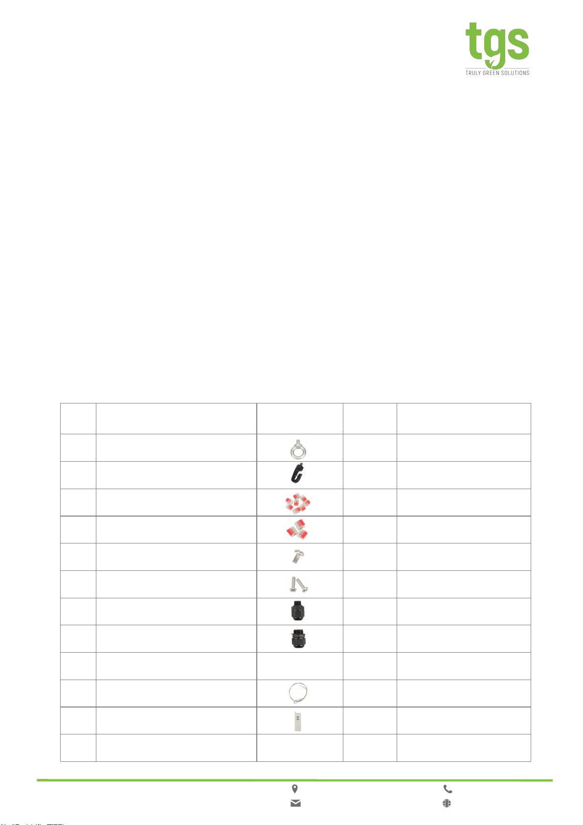
Accessories
# Name Referred
Photo
Quantit
yRemarks
1M12 Hanging Ring Bolt 1
2M12 Hanging Hook Bolt 1
3CM-221-2P Terminals 8
4CM-221-3P Terminals 3
56#-32*1/4 Screws 1
66#-32*5/8 Screws 2
7G(PF) ¼ Cable Grand Cord Grip 1
8G(PF) ½ Cable Grand Cord Grip 1
9Installation Manual Book -- 1
10 Stainless Steel Safety Rope 1Optional
11 Remote Controller 1Optional
12 6F22 9V Battery -- 1 Optional

Packaging
Name Parameter
Net Weight of
Singe Product 8.16 LB
Carton Size L14.57*W7.48*H13.38 Inch
Qty./Ctn 2 PCS
N.W./G.W of Carton 16.31 /18.08 LB
:9601 Variel Ave. Chatsworth, CA 91311
:info@trulygreensolu�ons.com
:818-206-4404
:www.trulygreensolu�ons.com
11
• It is recommended that the LED driver output should be directly connected to the LED light source, and
it is not appropriate to install other control devices between the output and the LED light source.
• If the product packaging is damaged, please confirm whether the product appearance is complete, and
cracks on the external structure of the product is not acceptable.
• This specification sheet will be subject to change without notice.
Shipment
Storage
RoHS
ATTENTIONS
•It is suitable for transportationby car, boat and airplane.
•Duringtransportation, it should be sheltered, sun-proof, and civilizedloadingand
unloading.
• Product storage should comply with GB 3873-83.
•If storage periodis les than a year, products should be re-examined.
• Products comply tothe European Standard 2011//65/EC

IMPORTANT SAFE GUARDS
When using electrical equipment and this lighting device basic
safety precaution should be followed at all times including but
not limited to the following:
PLEASE READ CAREFULLY AND FOLLOW ALL INSTRUCTIONS
FOR YOUR OWN SAFETY
WARNING: AC power must be turned off before proceeding with assembly or installation of emergency driver.
IMPORTANT: For use with non-dimming LED fixtures up to 40W. For use with LED fixtures(MAX 300W)
that utilize 0-10V dimming that are above 40W, but this inverter will be limited to 40W(Including driver).
IMPORTANT: An un-switched AC power source of 100Vac to 277Vac is required.
CAUTION: Make sure all electrical connections conform to the National Electrical Code and all applicable local
regulations.
CAUTION: Do not let power supply cords touch hot surfaces.
CAUTION: Do not mount near gas or electric heaters.
CAUTION: Use with grounded, UL Listed, dry or damp or wet location rated fixtures.
CAUTION: The equipment is intended for ordinary location and for permanent installation into one or more
Listed emergency luminaires.
CAUTION: Battery is a rechargeable LiFePO4 type and must be recycled or disposed of properly. Do not use
this emergency driver with accessory equipment other than recommended by the manufacturer; failure
to follow this may cause an unsafe condition. Servicing should only be performed by qualified service
personnel. Do not use this emergency driver for other than intended use. Not suitable for high-risk task area
lighting. Equipment should be mounted in locations and at heights where it will not readily be subjected to
tampering by unauthorized personnel.
IMPORTANT: Indicator (LED light) illuminated indicates battery in charge mode when AC power is applied. It
is recommended and required by applicable code to test emergency ballast to ensure proper function of the
system. Push the test switch every thirty (30) days to ensure the emergency driver is functioning by
illuminating the light source. Conduct a ninety (90) minutes discharge test once a year; LED light source
should be illuminated for a minimum of ninety (90) minutes .
TESTING SYSTEM: The emergency battery requires a charge minimum of 1 hour before testing the circuit. A
full charge requires 24 hours.
SAVE THESE INSTRUCTIONS
:9601 Variel Ave. Chatsworth, CA 91311
:info@trulygreensolu�ons.com
:818-206-4404
:www.trulygreensolu�ons.com
13
Other manuals for WP-EWG-040U
2
Table of contents
Other TGS Inverter manuals


 instruction manual")


