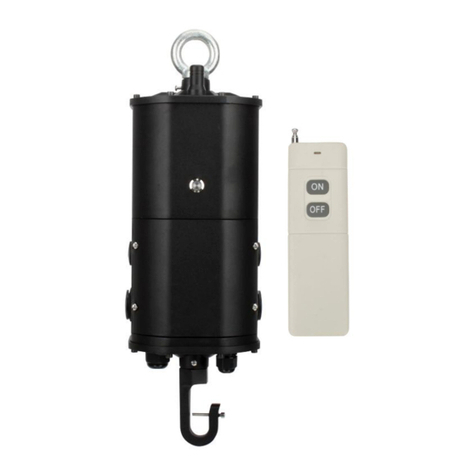
TGS WP-CEP-12C-200VPE User manual

WARNING: AC power must be off before proceeding with assembly or installation of emergency driver.
IMPORTANT: For use with non-dimming LED fixtures up to 12W. For use with LED fixtures(MAX 100W)
that utilize 0-10V dimming that are above 12W, but this inverter will be limited to 12W(Including driver).
IMPORTANT: An un-switched AC power source of 100Vac to 347Vac is required.
CAUTION: Make sure all electrical connections conform to the National Electrical Code and all
applicable local regulations.
CAUTION: Do not let power supply cords touch hot surfaces.
CAUTION: Do not mount near gas or electric heaters.
CAUTION: Use with grounded, UL Listed, dry location rated fixtures.
CAUTION: The equipment is intended for ordinary locations and for permanent installation into one or
more Listed emergency luminaires.
CAUTION: Battery is rechargeable Li-ion type and must be recycled or disposed of properly.
Do not use this emergency driver with accessory equipment other than recommended by manufacturer;
failure to follow this may cause an unsafe condition. Servicing should only be performed by qualified
service personnel. Do not use this emergency driver for other than intended use. Not suitable for high-risk
task area lighting. Equipment should be mounted in locations and at heights where it will not readily be
subjected to tampering by unauthorized personnel.
IMPORTANT: Indicator (LED light) illuminated indicates battery in charge mode when AC power is
applied. It is recommended and required by applicable code to test emergency LED Driver to ensure
proper function of the system; push the test switch every thirty (30) days to ensure the emergency driver
is functioning by illuminating the light source. Conduct a ninety (90) minutes discharge test one (1) time
per year; LED light source should be illuminated for a minimum of ninety (90) minutes .
TESTING SYSTEM: The emergency battery requires a charge minimum of one (1) hour before testing
the circuit. A full charge requires twenty four (24 Hours) .
Risk of Electric Shock
SAVE THESE INSTRUCTIONS
PLEASE READ CAREFULLY AND FOLLOW ALL
INSTRUCTIONS FOR YOUR OWN SAFETY
When using electrical equipment and this lighting device
basic safety precaution should be followed at all times
including but not limited to the following:
IMPORTANT SAFEGUARDS
Disconnect power at fuse or
circuit breaker before installing
or servicing
Installation And Operation Instructions
WP-CEP-12C-200VPE

PRODUCTION INFORMATION
Make sure that the luminaire used meets the voltage and current requirements in the
Product Information List and the illumination requirements in NFPA101.
•
Backup Inverter
•
Output Wattage: 12W
•
Universal Voltage: 100-347Vac, 50/60Hz
General Specifications
Input Voltage
Input Current
Input Power
Standby Input Power
Output Power(Emergency Mode)
Output Voltage Range
Number of Output Channels
RFI/EMI
Output Type
Service Life
100-347Vac, 50/60Hz
0.12A Max.
12W Max.
<0.8W (Finished charging)
Constant power
120-200Vdc
1 Channel
FCC Part 15 Class B
LED Class 1
50,000 hours
12W
Battery Type Li-ion 12.8Vdc
Battery Capacity Available
Battery Discharge Time
3000mAh(38.4WH)
90 Minutes Min.
Battery Recharge Time 24Hours
Driver Type
Maximum Load Power 100W(When dimming to a minimum, the power needs to be less than 12W)
Maximum standby time between Recharges 12 Month
Response time
≤5S
Ensure there will be sufficient light output in the end application. Estimate the egress lighting
illumination levels by doing the following:
a. Find the efficacy of the LED load. This can be provided by the luminaire manufacture. This number will be
given in lumens per watt (lm/w). It is the installer’s responsibility to validate the luminaire manufacturer’s efficacy
data. This can be accomplished by direct measurement, by review of independent 3rd party test data
(UL, ETL, etc.), accessing a public database of 3rd party data (such as Design Lights Consortium,
www.designlights.org), or other comparable means.
b. Lumens can be calculated by multiplying the output power of the backup inverter by the efficacy of the
LED load. In many cases the actual lumen output in emergency mode will be greater than this calculation gives,
however it will provide a good estimate for beginning the lighting design of the system.
C. Using the results of this calculation and industry standard lighting design tools, calculate the anticipated
illumination levels in the path of egress.
NOTE: This product has been designed to reliably interface with a wide selection of LED Drives. However,
compatibility cannot be guaranteed with all current and future LED systems. Compatibility testing of the end-use
system is suggested. Please contact the factory with any questions.
Lumens In Emergency Mode = Lumens per Watt of Fixture * Output Power of Choosen Product
_______________(Lumens) = __________________(lm/W) * 50(W)
TDB
Maximum mounting height

Input Surge Protection
Protections
Approvals / Class
2.5KV Ring Wave,L-N 3KV/1.5KA
Battery Over Discharge Protection
Output Short Circuit Protection
RoHS, UL8750 Listed, UL924 Listed, CEC Title 20
1. Manual Diagnostic Mode:
Under the normal charging mode, after the battery is charged for 12 hours or fully
charged, long press the test button for 3S and hold it, enter the manual test mode, release
the button to exit the manual diagnostic mode.
2. Enable / Disable Self-Diagnostic Test System:
Under the Normal Charging Mode, press the button twice in two seconds, then press
the button longer than 2S and less than 5S, then press the button twice in succession, the
indicator light will be on and off for 5 times (1S interval), means disable the Self-Diagnostic
Test System successfully. If you want to enable the Self-Diagnostic Test System, repeat
the operation, the indicator light will be on and off for 3 times (1S interval), means “Enable”.
3. Enter Sleep Mode:
Under EM mode, press the test button 3S, the Backup inverter will enter Sleep
Mode(Storage and transportation),and activate it by connecting to AC power.
●Solid Green ON
●
●
●
None LED OFF
●
Flashing Green, 1s on/1s off (cycle)
●
Slow Flashing Green, 5s on/5s off (cycle)
●
Flashing Green, 0.1s on/5s off (cycle)
Enable the Self-diagnostic test system.
Flashing Green, 1s on/1s off ( 5 times)
System OK/AC OK .
System NG,battery voltage is too low,
LED fixture is Short .
Battery not detected, check battery connection.
Discharge time is less than 90 minutes(Self-diagnostic test),
LED fixture is Open Circuit , Over Load .
EM working in Emergency mode.
Flashing Green, 1s on/1s off ( 3times)
Disable Self-diagnostic test system.
Dry, Damp Locations
4. Rest:
Under Error mode, press the test button 5S, the Backup inverter will Shutdown, and activate
it by connecting to AC power.
Ambient Operating Temperature Range
0°C to 50°C (32°F to 122°F)
In the normal charging mode, the system performs a monthly self-diagnostic test
every 30 days, the system switches to the emergency mode for 30S, and
automatically switches back to the normal charging mode after 30S.
Self-Diagnostic Test System
In the normal charging mode, the system switches to the emergency mode every
360 days (after 11 Months self-diagnostic test) and works until the end of
discharge. Automatically switches back to normal charging mode after discharge.
LED Indicators StatusTHE BACKUP INVERTER Status/Mode
TEST SWITCH INDICATOR STATUS:
TEST SWITCH OPERATION:

Wiring Diagram and Dimensions


> Disconnect all power sources to the lighting fixture and ensure they are locked out during installation or
maintenance.
> The AC driver must be sourced from the backup inverter.
> Select a suitable location for the backup inverter and install such that its output leads can connect to
the input leads of the AC driver.
Step #1 Disconnect AC Power From Fixture
Step #2 INSTALL THE BACKUP INVERTER
> Select a suitable location on the ceiling for hangable device.
> Install the ring bolt to the backup inverter and fix it with screw.
> Install the hook to the backup inverter and fix it with screw.
> Open the cover of junction box .
> Install the Bushing (BN-M12-8, E492547, ZHEJIAN BANGNAI ELECTRIC CO LTD
Suitable for wire diameter 4-8mm, STYLE,SJTW,SJOW,SVT )
> Install the Bushing (BN-M18-10, E492547, ZHEJIAN BANGNAI ELECTRIC CO LTD
Suitable for wire diameter 6-10mm, SJTW,SJOW,STYLE, SVT )
> Hang the backup inverter to the hangable device on the ceiling.
> Hang the LED ligthing fixture to the hook of the backup inverter.
> Install the Bx cables on AC wires and dimming wires .
> See Illustration 1, for typical installation and select appropriate mounting method
Step #3 WIRING THE BACKUP INVERTER
> Use the wiring diagram found on page 4 as reference.
> Connect the AC power source leads (Switched and Unswitched) to the input of the backup inverter.
> Connect the output leads of backup inverter to the AC driver.
> Wire the AC driver with the lamp in accordance with manufactures installation instructions.
> Make sure all connections are in accordance with the National Electrical Code, Canadian Electrical Code
> In a readily visible location, attach the label “Caution -This Unit Has More Than One Power Connection
Point. To Reduce The Risk Of Electric Shock, Disconnect Both The Branch Circuit-Breakers, Or Fuses And
DC Power Supply (Backup Inverter Connector) Before Servicing.”
and any local regulations.
Step #4 LOCK UP THE COVER OF JUCTION BOX & APPLY POWER
> After installation is complete, apply AC power .
> At this point, power should be connected to both the AC driver and the backup inverter, and the
Charging Indicator Light should illuminate indicating the battery is charging.
>A short-term discharge test may be conducted after the backup inverter has been charging for 1 hour.
Charge for 24 hours before conducting a long-term discharge test.
1 2
10 9
5
11
3
INSTALL STEPS
4
7
8

Illustration 1
Illustration 2
Table of contents
Other TGS Inverter manuals
Popular Inverter manuals by other brands

Weq
Weq AFW11 installation manual
Stober
Stober POSIDRIVE MDS 5000 Operation manual

Kaysun
Kaysun KSEF-22 DN5.0 Owners & installation manual
PAW
PAW SolarBloC midi Basic DN 20 Installation and commissioning instructions

Hitachi
Hitachi SJ700 Series Software manual

Chelion
Chelion iHome-B5-HD02 Series user manual
