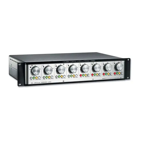
THÖRESS FFPre MKII User manual

THÖRESS
Full Function . Preamplifier
==========================
"FFPre MKII"
................................................................
I N S T R U C T I O N M A N U A L
Thank you for purchasing the THÖRESS Full Function Preamplifier (FFPre)!
You ha e acquired a ersatile acuum tube preamplifier incorporating a state-of-the-
art line control amplifier (2x12J5GT tubes) and a ground-breaking tube phono
equalizer (2x12JGT+2xPC86 tubes) in one chassis. The amplifier is built with
meticulous hand construction using our pro en point-to-point wiring techniques,
whereas much care has been taken in arranging each aspect of the internal
construction to ensure highest reliability, low noise performance and ease of ser ice
for many years to come. Please read the following explanations and instructions
carefully to get the most out of your FFPre.
INPUTS
The FFPre is equipped with a MC gain phono section with excellent signal-to-noise
performance implemented in purely acti e operation mode (no built-in step-up
transformers!) and three on-the-fly selectable phono inputs P1, P2, P3 with equal
gain status (65dB at 1kHz) yet different cartridge loading. Alternati ely, the FFPre is
a ailable with MM gain phono section (45dB at 1kHz) on demand. The standard
cartridge load pattern on the phono inputs of 3XMC and 3xMM units is
(P1, P2, P3)=(100, 200, 500) ohms and (P1, P2, P3)=(47, 47, 47)K
respecti ely.
The cartridge load values installed on the inputs of 3xMC units are printed on the rim of
the rear panel (under the lid) !
The phono inputs are complemented by three-line inputs with different gain and
input impedance characteristics as described below.
Normal Line Gain
The gain on input #6 is 26dB (20-times). This input presents a comparati ely high
input impedance of 80.000 ohm to the connected program source and is suitable for

classic line le el program sources such as phono preamplifiers, tape machines and
tuners.
Low Line Gain
Inputs #4 and #5 offer 18dB gain (8-times, 8dB lower gain compared to input #6) and
are meant for modern high-output digital sources such as CD/DVD players,
streamers or DAC-s. The input impedance on these inputs is 30.000 ohms.
Summarizing, the gain pattern on the inputs of the FFPre are
(MC, MC, MC; 18, 18; 26) dB and (MM, MM, MM; 18, 18; 26) dB
on 3xMC and 3xMM units respecti ely. Other gain patterns can be easily
implemented on demand, for example,
(MC, MC, MC; 10, 10; 18) dB or (MM, MM, MM; 18; 26, 26) dB.
OUTPUTS
The output impedance of the line section is sufficiently low (around 300 ohms) to
simultaneously dri e long cable lines and power amplifiers with an input impedance
as low as 10.000 ohms without compromising sound quality. The 3dB-down
frequency under 10.000 ohm loading is still well below the audio band (lower than
5Hz, line output coupling capacitor 3.3MFD).
The output of the line section is lead out through 2x2 RCA jack’s channel wise
connected in parallel (twin output). Thanks to the twin output it is possible to
simultaneously dri e a power amplifier and an acti e sub-woofer without further
adaptation in which case the effecti e load impedance (input loads of power
amplifier and subwoofer dri ing module in parallel) should preferably not come
significantly under 10.000 ohms. The twin output of the FFPre is also helpful for
proper dual-channel mono installation with SINGLE-COIL cartridges as described in a
dedicated paragraph of this manual.
Furthermore, the FFPre comprises a pass-through output (QUELLE) for the acti ated
input. This design choice ob iously allows to combine the internal phono section of
the FFPpre with an external line de ice.
The FFPre phono section can be tapped via the pass-through output!
In case of such an installation it is ad isable to connect the pass-through output to a
line input with high input impedance (equal or higher than 30.000 ohms) in order to
ensure a sufficiently low 3dB-down frequency of the low end response. The phono
output coupling capacitor (0.33MFD) has been chosen to gi e a 3dB-down frequency
of 5Hz when no additional external loading is imposed on the phono circuit ia the
pass-through output. In cases where line inputs with sufficiently high impedance are

not at disposal it is ad isable to install output coupling capacitors with higher
capacitance alues than 0.33MFD in the output of the phono circuit. For example, a
critically low effecti e load alue of 10.000 ohm would require a coupling
capacitance of 3.3MFD in order to maintain the original no-load 5Hz 3-dB-down
frequency, whereas 1MFD would gi e a still acceptable extension of the bass
response down to 15Hz.
Line amplification is performed by a unique single-stage, zero-feedback circuit
employing one 12J5GT acuum tube per channel (12SN7GT tubes in MKI units)
operated at high idle current. As a result of this purist concept the output signal is
phase-in erted (shifted by 180 degrees) relati e to the line and phono input signal.
Users who make a point of a formally correct o er-all signal phase can apply a simple
correcti e (in case it is known that all other components of the system offer phase
neutral operation).
To ensure a formall correct over-all phase of the signal in a setup including the FFPre the
loudspeakers must be connected to the power amplifier with reversed polarit (red
binding post of the amplifier connected to the black speaker terminal)!
PHONO EQUALIZATION
The gain of a phono pre-amplifier has to ary with frequency in order to restore the
pre-emphasis introduced to the signal during the record cutting process. Therefor a
phono pre-amplifier is sometimes called PHONO EQUALIZER (Phono Entzerrer). A
pre/de-emphasis characteristic is completely and unambiguously determined by a
set of edge frequencies (equi alent to so called time constants)
f1 > bass roll-off, f2 > bass turnover, f3 > treble roll-off.
The gain rises below f2 (bass boost) and falls off abo e f3 (treble attenuation/roll-
off) with a slope approaching 6dB/octa e. f2 determines the end point of the bass
boost. The difference between the arious pre/de-emphasis prescriptions
established by prominent record companies in the inception of high-fidelity audio is
rather small, often negligible, whereas in the most cases the crucial bass-turno er
frequency f2 equals 500 Hz. A few examples of prominent de-emphasis prescriptions
are gi en at the end of this manual.
The phono section of the FFPre performs highl accurate RIAA de-emphasis, (f1, f2, f3) =
(50, 500, 2124) Hz!
This most widely used equalization characteristic is gi en by the NEW
ORTHOPHONIC prescription established by RCA along with the microgroo e inyl
disc in the late 1940s, which later was appointed as phono playback standard.

PHONO CARTRIDGES
Early microgroo e records carry a monophonic signal written into a LATERALLY
excited triangular spiral groo e of constant depth. Such FIRST-GENERATION
microgroo es were originally meant to get tracked by a spherical 25-micron stylus
mounted to a MONO-FLEXIBLE cantile er (25-micron refers to the spike radius of the
diamond/sapphire tip). A mono-flexible cantile er is one which does not comply in
ertical direction.
By contrast, the groo e of a stereophonic record carries two signals (more or less
sharply separated from each other) coded LATERALLY AND VERTICALLY into the
groo e by also arying the depth of the groo e relati e to the record surface
(concomitant with the lateral groo e modulation). Consequently, stereophonic
cartridges are obligatorily fitted with an OMNI-FLEXIBLE cantile er, that is one which
complies in all degrees of freedom.
A phono cartridge with mono-flexible cantilever will seriousl and irrecoverabl damage
the groove when it is (accidentall ) used for tracking a stereophonic record!
A stereophonic cutting head produces a monophonic groo e when it is fed with
identical signals on both channels. A groo e obtained in this manner is significantly
narrower than a first-generation monophonic microgroo e, due to the new groo e
standards introduced for stereophony, whereas a 17-micron stylus was specified for
tracking such SECOND-GENERATION microgroo es. During the stereophonic era
more sophisticated stylus profiles (Shibata, Micro Ridge, Paratrace, Gyger, an-den-
Hull etc) ha e been de eloped from the humble spherical 17-micron stylus in order
to reduce tracking distortion and to enhance tracking ability of phono cartridges.
These modern stylus profiles pro ide the further ad antage of reduced record and
stylus wear on account of an increased contact area (line contact) between the
stylus tip and the groo e walls.
Phono cartridges with a sophisticated st lus profile tend to (drasticall ) outperform
humble cartridges fitted with a simple spherical st lus!
A phono cartridge with omni-flexible cantilever and a spherical 25-micron st lus can
faithfull track (NARROW) second-generation microgrooves, likel with reduced tracking
abilit , although this t pe of st lus was originall intended for tracking (WIDE) first-
generation microgrooves!
Conversel , ever phono cartridge with a spherical 17-micron st lus (or one of its modern
derivatives) can faithfull track (WIDE) first-generation microgrooves although this t pe
of st lus was originall intended for tracking (NAROW) second-generation microgrooves!
Stereophonic groo es are mono-compatible in a two-fold sense...
At first, e ery monophonic cartridge with omni-flexible cantile er (and a stylus
profile suitable for microgroo e reading) is able to faithfully track stereophonic

groo es whereas the fairly well separated R and L signals are con erted back into a
consistent mono signal. In this case the signal generator of the cartridge transforms
only the lateral excitations into signal. While ertical stylus mo ements do not
contribute to signal con ersion. Thus, monophonic cartridges ignore ertical stylus
mo ements e en when they are fitted with an omni-flexible cantile er. Secondly,
e ery stereophonic cartridge is able to read both, early and second-generation
monophonic microgroo es faithfully, whereas identical signals are de eloped in the
R and L channel generator coils. Hereby, the omni-flexible stylus, theoretically, is
exposed to lateral excitation only. Howe er, in reality ertical mo ements of the
stylus due to groo e imperfections (warp, dirt, scratches) are con erted into signal
and such add noise artifacts to the wanted cartridge output.
Ever stereophonic cartridge is capable of faithfull tracking both earl and second-
generation monophonic microgrooves, et it tends to produce more tracking noise than
dedicated mono cartridges!
Stereophonic cartridges with a sophisticated st lus are not onl suitable for faithfull
tracking (earl and second-generation) monophonic microgrooves but tend to
(drasticall ) outperform dedicated mono cartridges fitted with a humble spherical st lus!
The majority of currently produced high-grade monophonic MC cartridges are
deri ati es of stereophonic models and as such employ a dual-coil signal generator
(two separate generator coils terminating in 4=2x2 output terminals) with an omni-
flexible stylus. The only difference to the corresponding stereophonic ariants is that
the generator coils are not arranged at a 45-degree angle to the tracking plane, as it
is needed for stereophonic reading. Examples of omni-flexible dual-coil mono
cartridges are the AUDIO TECHNICA AT33-Mono, the LYRA mono cartridges and the
DYNAVECTOR DV-X1s-Mono.
Use a DYNAVECTOR DV-X1s-Mono for ultimate pla back of mono records with
microgroove coding!
Mono-flexible single-coil MC cartridges are currently produced by MIYAJIMA LAB in
Japan, all of which models (unfortunately) come with simple spherical stylus profiles.
The highly outstanding TEDESKA mono cartridges made in Berlin by Hyun Lee are
other examples of mono-flexible single-coil MC cartridges from current production.
Whereas the ORTOFON Mono CG-25 and the EMT OMD-25 are widely known classic
single-coil MC cartridges (pick-up heads). These old-timers offer an astonishingly
good sonic presentation e en when judged by today’s standards. Howe er, they
cause excessi e record and stylus wear due to their spherical diamond profiles and
tracking weights in excess of 4 grams, especially when combined with intage
tonearms without anti-skating facility. Their use is therefore questionable when
maximum sound quality and preser ation of aluable records is the main goal.
Ne ertheless, they will be an ob ious choice when it is aimed to compose a setup for
authentic monaural playback.

SINGLE-COIL MONO
A monophonic cartridge with DUAL-COIL generator outputs two copies of the
monophonic signal and therefor allows for dual-channel mono playback within the
regular stereophonic wiring scheme. Howe er, if the 4 input terminals of a
stereophonic phono preamplifier (hotL, groundL, hotR, groundR) with single-ended
(non-balanced) circuit topology are wired to a SINGLE-COIL cartridge through a
stereophonic tonearm cable, in an attempt to distribute the monophonic signal o er
the stereo channels for dual-channel mono playback, groundL and groundR will
una oidably meet at the cartridge terminals (2 contact pins) or within the cartridge
body (2x2 contact pins pairwise connected in parallel inside the cartridge body). This
unwanted conducti e connection will e oke residual hum in the amplifier due to the
so-called GROUND LOOP EFFECT. This is not a peculiarity of the FFPre but holds
generally for phono amplifiers with single-ended (non-balanced) circuit topology.
Single-coil phono cartridges cause residual hum when the are wired to both inputs of a
stereophonic phono preamplifier with non-balanced circuit topolog !
The FFPre allows for hum-free dual-channel mono playback with single-coil
cartridges on each indi idual phono input!
The key to hum-free dual-channel mono installation with single-coil cartridges in the
context of phono equipment with single-ended (non-balanced) circuitry is to
distribute the monophonic signal o er the R+L channels at the OUTPUT of the phono
preamplifier rather than at the cartridge terminals, in the manner described below.
Connect the L-plug of the (stereophonic) tonearm cable with the L-jack of the
chosen phono input, while the R-plug is let to hang freely, such a oiding a critical
conducti e connection between groundL and groundR. Isolate the armature of the
R-plug with the aid of a small glass test tube (or similar accessory) in order to
pre ent unwanted contacts. This installation permits hum-free amplification of the
monophonic signal in the L-section of the FFPre , while the R-section of the amplifier
runs at idle (is not fed with signal). Connect the ground wire of the tonearm cable to
the ground terminal of the chassis in the usual manner! Connect both plugs of the
interconnect cable (L+R power amplifier > FFPre) into the L-channel output jacks of
the FFPre (possible in iew of the twin output terminals of the FFPre). Now both
power amplifiers are dri en by the L-output signal of the FFPre (Y-connection). The
system is now ready for replaying mono records with single-coil cartridge in dual-
channel mono playback mode. Do not forget to restore the regular stereophonic
wiring scheme when the single-coil listening session is o er!
The s stem repla s the L-signal on both loudspeakers (rather than a consistent
stereophonic signal) when the s stem if fed with a stereophonic signal (from a
stereophonic cartridge or line level program source) while the s stem is wired for dual-

channel mono pla back in the above manner!
Some phono de ices with non-balanced circuit topology feature a so called MONO
SWITCH. Here the monophonic signal is distributed o er the channels at the input
(hence ground loop noise is induced), processed in the initial L and R amplifier stages
(distorted in each branch!), mixed together somewhere in the middle of the circuit
and then re-distributed o er both channels of the following circuitry, whereas the
ground loop noise introduced to the wanted signal in the initial amplifier stages
cancels away during the mixing process. Ob iously a clumsy and sound destructi e
concept!
Mono switches are sound destructive and go along with clums circuitr and are
therefore not helpful when ultimate sound qualit is the aim!
SUBSONIC ARTIFACTS
Coupling capacitor alues in the phono section of the FFPre ha e been carefully
chosen to ensure a low 3db down edge frequency at the low end while pro iding a
certain amount of attenuation of subsonic frequencies. Howe er, notably the phono
section of the FFPre does not incorporate dedicated subsonic filtering! The amplifier
will therefore pitilessly re eal subsonic artifacts which may ha e creeped in the
signal due to improper phono installation (turntable poorly isolated against structure
borne noise, too low resonant frequency of the tonearm-cartridge combination, or
comparable shortcomings).
The FFPre does not emplo high-slope subsonic filters!
High-slope subsonic filters do not solve but mask phono installation problems while
seriousl compromising sound qualit !
NOISE PERFORMANCE
Much care has been taken in arranging each aspect of the internal construction of
the FFPre so as to achie e an extraordinary signal-to-noise performance e en
though the phono amplifier operates in purely acti e manner (without the aid of
step-up transformers!). Howe er, electromagnetic stray fields emitted by mains
transformers or switching mode power supplies of other electronic de ices
positioned near the FFPre may, under unfortunate circumstances induce hum in the
amplifier ia electromagnetic interference. The phono section of the FFPre is
particularly susceptible to this kind of noise induction for ob ious reasons.
The FFPre requires considered placement for optimal signal-to-noise performance!
Place the FFPre on the right hand side of the rack in order to avoid/minimize
electromagnetic interference with other components of the setup!

Idle noise emitted by the FFPre line section may become audible in the system when
the gain of the power amplifier is rather high and not adjustable (as it is sometimes
the case with solid state de ices) or the loudspeaker is exceptionally efficient (horn
system), whereas a worst-case mismatch scenario will ob iously arise when both
conditions meet. In order to a oid idle noise issues and to ensure con eniently fine
olume adjustment, the gain of the power amplifier needs to be properly matched
to the line gain of the FFPre with respect to the efficiency of the loudspeaker. Proper
matching can be easily achie ed in case the power amplifier allows for gain
adjustment. In a matched scenario the olume controls rest near the middle position
for a saturated listening loudness (assuming that the program sources are connected
to line inputs with suitable gain figures).
Idle noise ma become audible in the s stem when the gain of the power amplifier is not
properl matched to the gain of the FFpre line section with respect to the efficienc of
the loudspeaker!
The input selector of the FFPre produces moderate switching noise when it is mo ed
in between the phono positions (P1, P2, P3) or from posP3 to pos4 or backwards,
particularly on (3xMC) units. This effect is not a peculiarity of our preamplifier and
would arise in the same manner with any kind of phono amplifier with on-the-fly
selectable inputs due to the extreme input sensiti ity of such de ices. The
magnitude of the noise emission is dependent on the gradation of the effecti e
impedances (internal impedance of the cartridge in parallel with the associated load
resistor) presented to the phono circuit on adjoining phono inputs. The noise
disturbances will ob iously remain inaudible and without impact when the olume
control is set to a low angle of rotation before mo ing the input selector.
Alwa s turn the volume controls to zero or at least to a ver low angle of rotation before
moving the input selector!
The FFPre outputs hiss when an open input (no cartridge connected) is switched
acti e, because in this case the thermal noise produced by the cartridge load resistor
Rmc is not shunted with the low impedance generator coils of a cartridge. The
magnitude of the hiss noise is proportional to the resistance alue of Rmc.
The FFPre is grounded in the sense that there is a conducti e connection between
the central zero point of the circuit and the ground terminal of the power inlet
module (and thus a conducti e connection between circuit zero potential and
earth/ground by means of the respecti e lead of the power chord). On rare
occasions, residual hum may arise in a setup with the FFPre due to the so called
ground loop effect, which typically comes into play when more than one component
of a system is grounded in the abo e sense.
Multiple grounding in a s stem can be resolved b interrupting abundant earth
connections either b adjusting ground lift switches or, in case ground lift switches are
not in place, b substituting 3-core power chords b 2-core parts!

The FFPre is equipped with six tubes (4x12J5GT+2xPC86 on MKII units and
4x12SN7GT+1xPCC88 on MKI units respecti ely). These tubes are unarguably among
the most linear amplification de ices e er de eloped in the history of electronic
technology. The amplifier comes with a set of new-old-stock tubes which ha e been
hand-picked to meet tight specifications.
The use of tubes with questionable characteristics ma lead to degraded noise and sonic
performance of the amplifier. Even serious damage ma occur in worst case scenarios!
Never switch on the amplifier unless ALL tubes have been installed!
Never pull a tube out of the socket while the amplifier is powered on!
Alwa s deinstall the tubes and wrap them up in the original protection case before
transporting or shipping the amplifier!
SETUP
To setup the FFPre power off all de ices of the system and proceed as follows.
0. Do not connect the amplifier to the mains until steps 1 to 8 ha e been taken.
1. Make sure that the frontal power switch (NETZ) rests in OFF (AUS) position.
2. Bring the master power switch on the power inlet module into the ON position.
Switch off the amplifier at the power inlet when the unit will not be used for a longer
period of time!
3. Ascertain that both olume control knobs rest in zero position or at least at a ery
low angle of rotation.
4. Remo e the top lid of the amplifier (eight metric 2.5 Allen-screws to release) and
install the tubes carefully. Ascertain that the guide pin of the octal base tubes is
properly aligned with the socket opening! Tighten the screws properly when
reinstalling the lid so as to ensure a proper conducti e connection between the lid
and the chassis. Take care to place the lid on the chassis with correct orientation (5
slot stars head-on, 4 stars on the rear side).
Never power on the FFPre unless ALL tubes have been installed!
Never pull a tube out of the socket while the amplifier is powered on!
Alwa s deinstall the tubes and wrap them up in the original protection case before
transporting or shipping the amplifier!
Keep the original crate (including the four soft foam inla s and the tube protection case)
for later use. It has been specificall designed for safe transport under rough conditions!
5. Bring the FFPre into its final position. Obser e the remarks made on optimal
positioning in the paragraph NOISE PERFORMANCE.
The FFPre requires considered placement for noise-free operation!

Place the FFPre on the RIGHT side of the rack to avoid/minimize electromagnetic
interference with other components of the s stem!
6. Connect phono cartridges to suitable phono inputs (P1, P2 or P3). Do not forget to
connect the ground wire of the tonearm cables to the ground terminal adjacent to
the phono inputs. If one or more single-coil cartridges is to be used in dual-channel
mono playback mode, follow the instructions gi en in the respecti e section of this
manual to ensure a proper installation. Note that the amplifier is internally grounded
in the sense that there is a conducti e connection between the central zero point of
the circuit and the ground terminal of the power inlet module (and thus a
conducti e connection between circuit zero and earth/ground by means of the
respecti e lead of the power chord).
7. Connect line le el program sources to suitable line le el inputs (4/5/6).
8. Connect the FFPre to the power amplifier (acti e loudspeaker, subwoofer).
Choose a reasonably low gain on the power amplifier in case this de ice allows for
gain adjustment. If our EHT mono block is used for power amplification, set the gain
selector to position 1 (lowest possible gain). Re-consider/adjust the gain setting on
the power amplifier after the setup has been completed until optimal gain matching
between the FFPre and the power amplifier is attained with respect to the efficiency
of the loudspeaker. This is the case when the olume controls of the FFPre rest close
to the middle position for con enient listening loudness.
9. Connect the FFPre to the mains with a 3-core power chord.
10. Power on the program sources.
11. Select the desired program source with the input selector.
12. Power on the program sources (while the FFPre is still powered off).
13. Switch on the FFPre while the power amplifier remains powered off. Wait for at
least 1 minute until the warm-up process on the amplifier has come to an end.
When powering on the s stem, alwa s switch on the program sources and the FFPre
before the power amplifier, observing a dela of at least 1 minute!
14. Complete the setup procedure by switching on the power amplifiers (acti e
speakers, subwoofer).
Never switch the FFPre on or off while the power amplifier is on!
When powering off the s stem, alwa s switch the FFPre and the program sources AFTER
the power amplifier, observing a dela of at least 30 seconds!
FUSE
The FFPre draws a current of 0.3A/0.6A from the 230Vac/115Vac mains
corresponding to a power consumption of 70 watts. It is protected with a
1A slow-blow 5x25mm fuse

in the power inlet module. On rare occasions, the fuse may blow at the switching-on
moment due to the current spike drawn by the mains transformer in this instant.
Should this condition arise more regularly it is ad isable to use a fuse with slightly
higher current rating.
ULTRASONIC RECORD CLEANING
Record cleaning is a crucial activit for all vin l lovers who wish to full exploit the sonic
capabilities of the FFPre!
Step 1
Roughly clean a lot of records with a microfiber cleaning fabric.
Step 2
Let the records rotate in the bath of an industrial grade (6 liter) ultrasonic cleaning
machine (USCM) for at least half an hour with the aid of the KUZMA rotator kit or
similar de ice. Use demineralized water and a few drops of dish cleaning
concentrate as cleaning fluid heated up to about 45deg Celsius. Use a EMAG 60HC
(Made in Germany) USCM for optimal cleaning results.
Setp 3
Take the records out of the bath one after another and acuumize them on a
con entional record cleaning machine such as the Nitty Gritty (platter with LP label
size) or Okki Nokki (rubber coated full size platter!) while they are still wet. Notably,
in case of the Okki Nokki the platter needs to get dried up before the record can be
flipped. The acuuming procedure is obligatory and must not be omitted. Air-drying
or blow-drying of the records after the ultrasonic cleaning treatment is highly
counterproducti e.
Step 4
Let the record air-dry for a little while and put it in a pristine slee e.
F A T U R O V R V I W
•Reference grade acuum tube line control amplifier and state-of-the-art acuum
tube phono equalizer within one chassis.
•Purely acti e MC gain phono section (70dB@1KHz) with excellent signal-to-noise
performance (no built-in step-up transformers). Alternati ely, MM gain
(45dB@1KHz) can be installed in the phono section on request.
•Highly accurate RIAA equalization (passi e de-emphasis implementation).
•Minimalist single-ended zero-feedback schematics throughout.
•Six inputs (3 phono + 3 line) with gain pattern (MC, MC, MC; 18, 18; 26) dB.
•Channel-separate manual olume control ia high-grade continuously- ariable
rotary potentiometers with low angle sensiti ity (con eniently fine olume
adjustment).

•2x line outputs with low output impedance.
•Pass-through output for the acti e input.
•Ultra low noise and leakage mains transformer produced in-house for 230Vac
(115Vac ia jumper setting), 100Vac (Japan), 120Vac (USA, Canada), 220Vac
(South Korea, China, Thailand, Indonesia), 240Vac (UK) or 245 Vac (Australia).
•Full hand c
•onstruction, point-to-point wiring throughout.
•Nonmagnetic aluminum casework, anodized printing on front and rear panel,
powder-coated lids.
•Dimensions: 434x434x154 mm, 154=134+20 (feet).
•Dimensions of the shipping box: 650x650x350 mm, weight 11.5 Kg.
................................................................
THÖRESS...
A Tribute to Professional Audio Components
from the Golden Age of the lectronic Tube !
................................................................
Table of contents
Other THÖRESS Amplifier manuals

THÖRESS
THÖRESS Full Function Integrated "Super"... User manual
THÖRESS
THÖRESS F2a11 User manual
THÖRESS
THÖRESS EHT Integrated Amplifier MKII User manual

THÖRESS
THÖRESS Parametric Phono Equalizer Series User manual

THÖRESS
THÖRESS 300B User manual

THÖRESS
THÖRESS SE845 Mono User manual
THÖRESS
THÖRESS EHT Mono Block User manual

THÖRESS
THÖRESS SE300B User manual
