Thames & Kosmos Code Gamer User manual
EXPERIMENT MANUAL
620141-03-090816
Franckh-Kosmos Verlags-GmbH & Co. KG, Pfizerstr. 5-7, 70184 Stuttgart, Germany | +49 (0) 711 2191-0 | www.kosmos.de
Thames & Kosmos, 301 Friendship St., Providence, RI, 02903, USA | 1-800-587-2872 | www.thamesandkosmos.com
Thames & Kosmos UK Ltd, Goudhurst, Kent, TN17 2QZ, United Kingdom | 01580 212000 | www.thamesandkosmos.co.uk
CodeGamer manual cover english.indd 1 8/9/16 10:04 AM
› › › IMPORTANT INFORMATION
Safety Information
WARNING!Only for use by children aged 10 years and older.
Instructions for parents or other supervising adults are included and
have to be observed. Keep the packaging and instructions as they
contain important information.
WARNING!Not suitable for children under 3 years. Choking hazard
— small parts may be swallowed or inhaled.
Safety for Experiments with the Rechargeable Battery
››› A lithium polymer rechargeable battery is required for
the experiments. Please use only the battery supplied
with the kit!
››› The rechargeable battery is only to be charged under
adult supervision.
››› Never perform experiments using household current!
The wires are not to be inserted into socket-outlets.
The high voltage can be extremely dangerous or fatal!
››› The battery is not to be short-circuited. It could
overheat and explode!
››› Do not connect the battery’s terminals to each other.
››› The battery is to be inserted with the correct polarity.
››› Avoid deforming the battery.
››› The battery is to be removed from the toy if it is
defective.
››› Keep the kit out of the reach of small children.
››› When assembling the device and installing the
battery, follow the instructions in this manual in
order to avoid destruction of components.
Dear Parents and Supervising Adults,
This experiment kit will introduce your child to the exciting world of
programming in a fun way.
Please be available to provide your child with help, advice, and
support.
It is natural to have questions about safety. This kit meets
U.S. and European safety standards. These standards impose
obligations on the manufacturer, but also stipulate that adults
should provide their children with advice and assistance during the
experiments.
Tell your child to read all the relevant instructions and
safety information, and to keep these materials on hand for
reference. Be sure to stress the importance of following all the rules
and information when performing the experiments.
We wish your child, and of course you as well, lots of fun
and success with the experiments!
Disposal of Electrical and Electronic Components
This product’s electronic parts are reusable and, for the
sake of protecting the environment, they should not be
thrown into the regular household trash at the end of
their lifespan. Instead, they must be delivered to a
collection location for electronic waste, as
indicated by the following symbol:
Please consult your local authorities for
the appropriate disposal location.
Disposal of Battery
The battery does not belong in the
household trash! In some states and
countries, it is required by law to deliver
batteries and rechargeable batteries to a local collection
location or to a store. This will ensure that they will be
disposed of in an environmentally responsible manner.
Batteries containing hazardous substances are identified
by this image or by chemical symbols (Cd = cadmium,
Hg = mercury, Pb = lead).
Simplified EU Declaration of Conformity
Thames & Kosmos hereby declares that the KosmoBits
radio communication unit model 620141 conforms to
Directive 2014/53/EU.
The complete text of the EU conformity declaration is
available at the following Internet address: http://
thamesandkosmos.com/codegamer/declaration.pdf
Safe Handling of Electronic Components
››› Avoid contact with metallic objects and fluids of any
kind!
››› After experimenting, pack all sensitive components in
the bags provided for them and keep them together
with the other parts in the experiment kit box.
››› If the KosmoBits hardware is not to be used for a long
period of time, please disconnect the battery’s
connection wire from the interaction board.
The toy is only to be connected to Class II equipment
bearing the following symbol:
Kosmos Quality and Safety
More than one hundred years of expertise in publishing science
experiment kits stand behind every product that bears the Kosmos
name. Kosmos experiment kits are designed by an experienced
team of specialists and tested with the utmost care during
development and production. With regard to product safety, these
experiment kits follow European and US safety standards, as well
as our own refined proprietary safety guidelines. By working
closely with our manufacturing partners and safety testing labs,
we are able to control all stages of production. While the majority
of our products are made in Germany, all of our products,
regardless of origin, follow the same rigid quality standards.
1st Edition 2016
© 2016 Franckh-Kosmos Verlags-GmbH & Co. KG,
Pfizerstr. 5-7, D-70184 Stuttgart, Tel. +49 (0) 711 2191-343
This work, including all its parts, is copyright protected. Any use outside the specific limits of
the copyright law without the consent of the publisher is prohibited and punishable by law.
This applies specifically to reproductions, translations, microfilming, and storage and
processing in electronic systems and networks. We do not guarantee that all material in this
work is free from copyright or other protection.
Project management: Jonathan Felder, Marc Gänssler, Sebastian Martin
Text and experiments: Felix Homann
Product development: Steffen Rothweiler
Manual design concept: Atelier Bea Klenk, Berlin
Layout and typesetting: Michael Schlegel, komuniki, Würzburg
Illustrations: Michael Schlegel, komuniki, Würzburg
Manual photos: picsfive (all pushpins); askaja (all paper clips); Jaimie Duplass (all tape strips)
(all © fotolia.com); 8vFanl (p. 61 bottom right); hopsalka (p. 61 top); krista (p. 2 bottom left, p.
21 bottom right); tepic (p. 20 bottom) (all © iStockphoto.com); Designua (p. 38 bottom) (©
shutterstock.com); leejeongsoo (p. 35 bottom); theSOARnet (p. 38 top); Petr Kratochvil (p. 33
top) (all © pixabay.com); Johannes (p. 2 center right, p. 21 top right); Willi Heidelbach (p. 27)
(all published under CC BY-SA 2.5, viewable under https://creativecommons.org/licenses/by-
sa/2.5/deed.de); Philip Steffan (p. 60 all, © Make magazine); all screenshots of the Arduino
program © Arduino; Andreas Resch, argfx, St. Ulrich am Waasen (front cover, p. 1 rendering
gamepad, p. 1 and p. 32 SensorBots); Michael Flaig, proStudios, Stuttgart (p. 1 additional
materials); Matthias Kaiser, Stuttgart (all other photos)
Packaging design concept, layout and typesetting: Michael Schlegel, komuniki, Würzburg
Packaging photos: Andreas Resch, argf x, St. Ulrich am Waasen (all renderings); Michael Flaig,
pro-studios, Stuttgart (materials photo)
The publisher has made every effort to locate the holders of image rights for all of the photos
used. If in any individual cases any holders of image rights have not been acknowledged, they
are asked to provide evidence to the publisher of their image rights so that they may be paid an
image fee in line with the industry standard.
Android, Google Play and the Google Play logo are trademarks of Google Inc.
Apple and the Apple Logo are trademarks of Apple Inc., registered in the USA and other
countries. App Store is a service mark of Apple Inc.
1st English Edition © 2016 Thames & Kosmos, LLC, Providence, RI, USA
Thames & Kosmos® is a registered trademark of Thames & Kosmos, LLC.
Translation: David Gamon; Editing: Camille Duhamel and Ted McGuire; Additional Graphics
and Layout: Dan Freitas
Distributed in North America by Thames & Kosmos, LLC. Providence, RI 02903
Phone: 800-587-2872; Web: www.thamesandkosmos.com
Distributed in United Kingdom by Thames & Kosmos UK , LP. Goudhurst, Kent TN17 2QZ
Phone: 01580 212000; Web: www.thamesandkosmos.co.uk
We reserve the right to make technical changes.
Printed in China / Imprimé en Chine
FCC Part 15 Statement
This device complies with Part 15 of the FCC
Rules. Operation is subject to the following
two conditions: (1) this device may not cause
harmful interference, and (2) this device must
accept any interference received, including
interference that may cause undesired
operation.
Warning: Changes or modifications to this unit
not expressly approved by the party
responsible for compliance could void the
user’s authority to operate the equipment.
NOTE: This equipment has been tested and
found to comply with the limits for a Class B
digital device, pursuant to part 15 of the FCC
Rules. These limits are designed to provide
reasonable protection against harmful
interference in a residential installation. This
equipment generates, uses and can radiate
radio frequency energy and, if not installed
and used in accordance with the instructions,
may cause harmful interference to radio
communications.
However, there is no guarantee that
interference will not occur in a particular
installation. If this equipment does cause
harmful interference to radio or television
reception, which can be determined by turning
the equipment off and on, the user is
encouraged to try to correct the interference
by one or more of the following measures:
• Reorient or relocate the receiving antenna.
• Increase the separation between the
equipment and receiver.
• Connect the equipment into an outlet on a
circuit different from that to which the receiver
is connected.
• Consult the dealer or an experienced radio/
TV technician for help.
Shielded cables must be used with this unit to
ensure compliance with the Class B FCC limits.
FCC RF Exposure Statement
To comply with the FCC RF exposure
compliance requirements, this device and its
antenna must not be co-located or operating
in conjunction with any other antenna or
transmitter.
For body worn operation, this device has been
tested and meets FCC RF exposure guidelines
when used with an accessory that contains no
metal and that positions the device a minimum
of 5 mm from the body. Use of other
accessories may not ensure compliance with
FCC RF exposure guidelines.
IC Statement
RSS-Gen & RSS-247 statement:
• This device complies with Industry Canada
licence-exempt RSS standard(s).
• Operation is subject to the following two
conditions: (1) this device may not cause
interference, and (2) this device must accept
any interference, including interference that
may cause undesired operation of the device.
• Le présent appareil est conforme aux CNR
d‘Industrie Canada applicables aux appareils
radio exempts de licence.
• L‘exploitation est autorisée aux deux
conditions suivantes : (1) l‘appareil ne doit pas
produire de brouillage, et (2) l‘utilisateur de
l‘appareil doit accepter tout brouillage
radioélectrique subi, même si le brouillage est
susceptible d‘en compromere le
fonctionnement.
RSS-102 Statement:
• This equipment complies with Industry
Canada radiation exposure limits set forth for
an uncontrolled environment.
• Cet équipement est conforme à l‘exposition
aux rayonnements Industry Canada limites
établies pour un environnement non contrôlé.
1000 1001
1101 101 00
100 10
1010
0
CodeGamer manual cover english.indd 2 8/9/16 10:04 AM
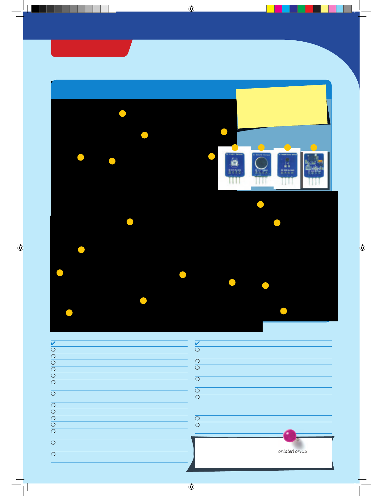
What’s inside your experiment kit:
Checklist: Find – Inspect – Check off
No. Description Quantity Item No.
1 KosmoDuino 1 717 982
2 Interaction board 1 717 981
3 Gamepad housing, top right 1 718 006
4 Gamepad housing, top left 1 718 007
5 Gamepad housing, bottom 1 718 005
6 Wheel with return spring 1 718 008
718 009
7 Buttons with rubber feet 1 718 010
718 011
8 Light sensor 1 717 985
9 Sound sensor 1 717 986
10 Temperature sensor 1 717 984
11 Motion sensor 1 717 983
12 Housing for sound sensor 1 718 000
718 004
13 Housing for light sensor 1 717 999
718 003
14 Housing for temperature sensor 1 717 997
718 001
No. Description Quantity Item No.
15 Housing for motion sensor 1 717 998
718 002
16 Breadboard 1 717 996
17 Jumper wires 10 717 990
male-female
18 Jumper wires 10 717 989
male-male
19 Resistors: 330 Ohm 5 717 991
20 LEDs: yellow 1 each 717 994
green 717 993
blue 717 995
red 717 992
21 Cable: USB to Micro-USB 1 717 988
22 Lithium polymer battery, 800 mAh 1 717 987
(not shown)
You will also need:
Smartphone or tablet with Android (4.3 or later) or iOS (Version
7 or later). The device must support Bluetooth 4 or higher. PC
with Internet access.
10
6
11
15
8
2
14
9
13
7
17
16
18 19
20
21 12
5
4
13
62 0141- 0 2-19 0716
GOOD TO KNOW! If you are missing any
parts, please contact Thames & Kosmos
customer service.
US: techsupport@thamesandkosmos.com
UK: techsupport@thamesandkosmos.co.uk
CodeGamer
› › › KIT CONTENTS
CodeGamer manual inside english.indd 1 7/19/16 12:31 PM

Safety Information .................................................. Inside front cover
Kit Contents..............................................................................................
Table of Contents.....................................................................................
How to get started with CodeGamer ......................................................
Assembling the gamepad and sensors
The CodeGamer app
The World of the Microcontroller .............................................................
First steps ......................................................................................................
Installation of the Arduino Software
Project : Blink! ..................................................................................................
Upload a program to your KosmoDuino
Project : Off switch ........................................................................................
Project : On switch .........................................................................................
The Interaction Board .....................................................................................
Project : Colored light .....................................................................
Project : At the push of a button ....................................................
Project : A blinking die .....................................................................
Project : Serial monitor .....................................................................
The for loop ...........................................................................................
Sensors ....................................................................................................
Project : Thermometer ........................................................................
Project : Finger disco ...........................................................................
Project : Cheep! ...................................................................................
Project : Random sounds! ..................................................................
Project : Siren ......................................................................................
Project : Musical scale .....................................................................
Project : Sensor organ ......................................................................
Project : The serial plotter .............................................................
Project : Clap switch ......................................................................
Project : Drawer monitor ..............................................................
Project : Looking inside the fridge ..............................................
Project : Ghostly eyes ...................................................................
Common Error Messages ...............................................................................
Notes ...................................................................................................................
Publisher’s Information .......................................................Inside back cover
TIP !
You will find additional information on
the “Check It Out” pages (21, 59-61)
and “Knowledge Base” pages (24-25,
35, 41-42, and 58).
› › › TABLE OF CONTENTS
1000 1001
1101 101 00
100 10
1010
0
CodeGamer manual inside english.indd 2 7/19/16 12:31 PM
1
2
3
4
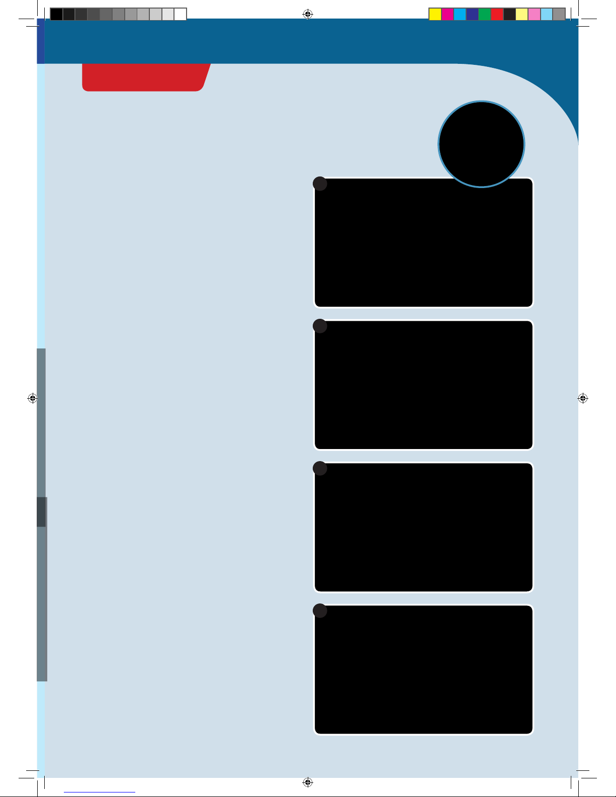
How to get started with CodeGamer
ASSEMBLING THE GAMEPAD
1. First of all, you will have to insert the little metal spring
into its correct location in the left area of the bottom part
of the housing. The spring will hold the wheel and ensure
that it always returns to its original position.
2. Next, you will have to insert the narrow axle of the
wheel into the rotation encoder hole. The rotation
encoder is attached to the interaction board and marked
there.
3. Connect the battery to the interaction board. The
attachment is on the bottom side. The battery’s plug is
shaped in such a way that it can only be connected in
the correct polarity direction. Do not force it!
4. Now place the battery in the lower housing of the
interaction board. Insert it so that it is securely mounted
and does not jiggle.
CodeGamer
GETTING STARTED
CodeGamer manual inside english.indd 3 7/19/16 12:31 PM
5
6
7
ASSEMBLING THE SENSORBOTS
1. Take one of the sensors and look for the housing with
the matching color (see page 1, “Kit Contents”). Insert
the sensor front side forward into the half of the housing
with the eyes printed on it. The sensors’ “feet” (the metal
pins) are always closer to the back side.
2. Now all you have to do is attach the rear of the housing
to the front part. To do that, just press the two parts
firmly together.
5. Now you can insert the interaction board into the
housing. Be sure that the wheel is mounted correctly in
the spring (see image in circle).
6. Attach the gray rubber feet onto the bottom of each
button. To do this, simply insert the thinner side of the
rubber foot into the recess on the bottom of the button.
Then, insert the button plate into the right upper
gamepad housing. Be sure that the buttons are
positioned correctly. You know that everything is
correctly placed when you feel an explicit trigger point
when the buttons are pushed. Then, attach the left
upper housing.
7. Your gamepad is now completed except for its “control
center,” the KosmoDuino. You can simply attach this to
the interaction board. Make sure that all the pins fit and
do not bend when you attach it. Press the KosmoDuino
far enough in that its “feet” (the metal pins) are no
longer visible.
CodeGamer manual inside english.indd 4 7/19/16 12:31 PM

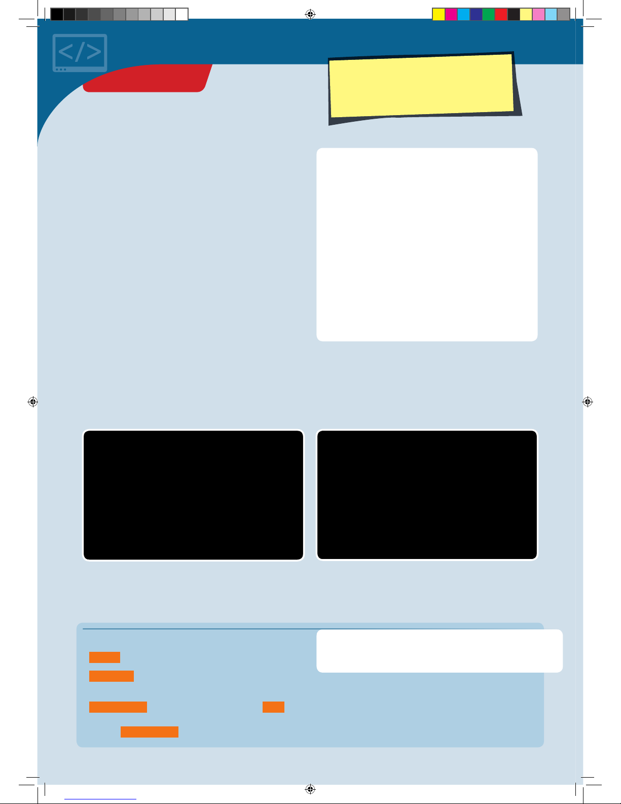
◀▲Various CodeGamer App screenshots
THE APP
To ease your entry into the world of programming, we
have developed an app to help you start building
experience in this area.
The core of the app is a video game in which you have to
solve little programming puzzles. But don’t be afraid — they
aren’t hard, and you will definitely be able to figure them
out. The key to solving the puzzles lies with the code
monsters that you will find at every level. Collect them all,
because you will need them at the computer terminals. The
computer terminals contain incomplete code. To fill in the
blanks, you will need to drag the correct code monster into
the matching blank spaces. To learn more about the
monsters, just tap once or twice on them in your inventory
— and they will tell you which blank space in the code they
will complete.
Use your gamepad to control the characters in the game.
To do this, you must have Bluetooth activated on your
tablet or smartphone. Start the app and switch on the
gamepad by sliding the switch at the upper edge to the
“ON” position. The connection will then be made
automatically in a few seconds. Once the connection is
active, the control elements (arrows and A and B buttons)
will disappear from the screen and you can control the
app with just the gamepad. If you switch off your
gamepad, the control elements will reappear. But the
game is not nearly as much fun without the gamepad!
CodeGamer
SYSTEM REQUIREMENTS:
KosmoBits supports devices with
Android 4.3 and iOS 7 operating
systems or later. The device has
to support Bluetooth 4 or higher.
Important! Take the time to
read the information, tips, and
hints presented in the
communication console here.
CodeGamer manual inside english.indd 5 7/19/16 12:31 PM
▲KosmoBits controller
!
HOW TO DOWNLOAD THE FREE APP:
To install your app, you will need access to Google Play or the Apple App Store. Ask
your parents or adult supervisor for help installing the app.
If your device runs on Android, open Google Play. Open the App Store with an iPhone or
iPad. Just enter the search term CodeGamer and install the app.
You will need your four sensorbots to play the game.
They are very handy for helping to clear obstacles out of
your way in the game. You can simply insert them into
your gamepad (see picture). As soon as you have inserted
a sensorbot, your game character will turn into one of the
four bots. Each one has its own special abilities. If you
have inserted the blue “Newton” bot, for example, you will
have to shake your gamepad vigorously back and forth to
activate its abilities. We will let you find out on your own
how to activate the special abilities of the other
sensorbots.
Play the game once through and take a look at the other
contents of the app in the main menu. You will find a lot
there about your experiment kit and the topic of
programming.
We hope you have a lot of fun experimenting with code!
The World of the
Microcontroller
Welcome to the world of the microcontroller! It looks
astonishingly similar to your own world. Or more
precisely: It looks exactly like your own! All around you,
there are countless microcontrollers going about their
work unnoticed. There’s hardly any electronic device that
works without a microcontroller
—
an electrical
toothbrush, the remote control for your TV, the controller
for your video gaming system, a digital thermometer, a
talking doll, a barking toy dog, the washing machine, the
smoke detector, the toaster, and so on …
CodeGamer manual inside english.indd 6 7/19/16 12:31 PM
!
WHAT DOES ARDUINO MEAN, ANYWAY?
In this instruction manual, you will come across the word
“Arduino” a lot. That is the name for a widely-used microcontroller
platform on which the KosmoDuino was based.
For a long time, microcontroller programming was only for
specialists. In 2005, the founders of the Arduino project took it
upon themselves to make the programming and use of simple
microcontrollers as easy as possible. That way, art students and
hobbyists who had never before had any experience with
programming would be able to use microcontrollers in their work.
Since then, a large community has formed around the Arduino
platform and lots of interesting projects have developed out of it.
You can copy a lot of them with your KosmoDuino, which is
compatible with an Arduino Uno board.
You can learn more about the Arduino project at www.arduino.cc.
BUT WHAT IS A
MICROCONTROLLER?
A microcontroller is a small (“micro”) computer. But it is
also fundamentally different from the computers that you
normally deal with: It has no keyboard, no mouse, and no
screen.
Instead, it has a lot of little feet, known as pins. A pin is
something like a connection between the microcontroller
and the outside world. Some of the pins have specified
functions. Most, however, are so-called GPIO pins. That’s
an abbreviation for General Purpose Input/Output. These
GPIO pins can be used for both inputs and outputs. And
that’s just what you need here.
. INPUT:
You can connect an input pin to a sensor, for example. This
will monitor the outside world and send information
about the surroundings, temperature, or brightness to the
processor via fluctuating levels of electrical voltage. In
your gamepad, an input pin is also activated when you
press a button.
. OUTPUT:
Depending on how it is programmed, the processor can
also respond to this information. For that, you will need
output pins to establish the connection to LEDs or the
sound module, which will then react to the level of the
transmitted electrical voltage by emitting various sounds
or colors.
Things really get exciting when you use several pins at the
same time. That way, the microcontroller can react to the
sensors all on its own — for example, by sounding an
alarm when it gets too hot.
The thing your microcontroller has in common with a
normal computer is the main processor that serves as the
brain of any computer. That’s the little black square at the
top left of your microcontroller. In the middle, there is a
small processor. This is what is responsible for the
communication between the microcontroller and the PC.
At the right is the Bluetooth chip, which enables wireless
connections with other devices.
CodeGamer
CodeGamer manual inside english.indd 7 7/19/16 12:31 PM

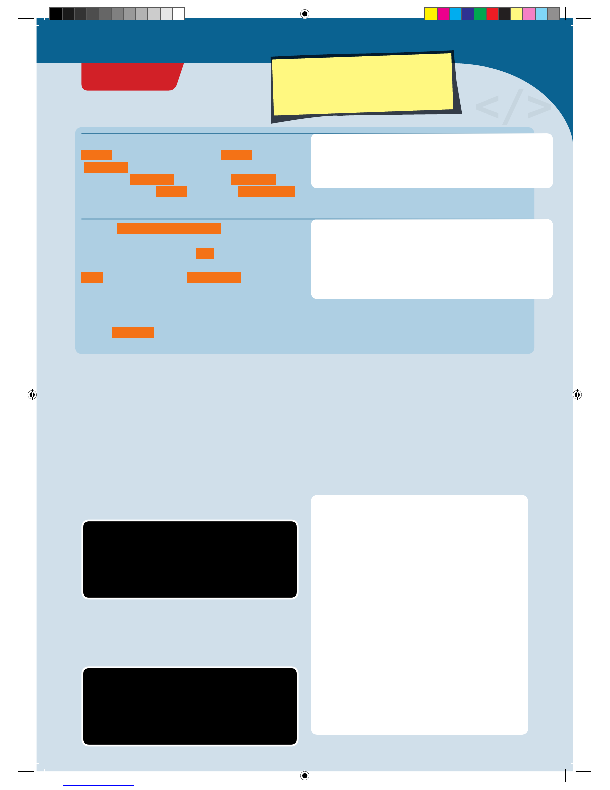
▲Download page on www.arduino.cc
Preparation
To program your KosmoDuino, you will need an ordinary PC
or laptop with the Arduino software installed on it. The
software is also called a programming environment, since it
includes a lot of tools that you will need for programming.
INSTALLATION OF THE ARDUINO
SOFTWARE
Download the Arduino software from https://www.
arduino.cc/en/main/software. On that page, you will find
various versions for the current operating systems. For
Windows operating systems, select “Windows Installer.”
After downloading, execute the downloaded file. Since the
Arduino software is constantly being revised, there are
always new versions. At the time that this manual was
printed, 1.6.6 was the current version, and the file was
called arduino-1.6.6-windows.exe. However, we
recommend working with version .., since this is the
version that was extensively tested by us. You will find
older versions on the “PREVIOUS RELEASES” page. After
starting the installer, follow the instructions to complete
the installation.
INSTALLATION OF THE KOSMOBITS
LIBRARIES AND SAMPLES
In a software library, you will find lots of useful and
reusable functions that will make programming easier for.
The ones we developed are called the KosmoBits libraries.
They also contain a lot of sample programs that you will
find in this manual. You must install these libraries.
The KosmoBits libraries can be downloaded by entering
http://thamesandkosmos.com/codegamer/kosmobits_
archive.zip link into your web browser. The file is called
kosmobits_archive.zip. This is a zip file that you will have
to unzip and move into the Arduino libraries folder.
On the next page, you will be asked for a contribution. The
Arduino project, which promotes the development of the
Arduino software, is largely financed by these kinds of
donations. You can also download the software for free
without making a donation by clicking on “Just
Download.”
Windows:
1. Open the explorer.
2. Go to the downloads folder.
3. Double-click the kosmobits_archive.zip file to open
it.
4. Select all the files and folders in the libraries folder
by simultaneously pressing the “Ctrl” and “A” keys.
5. Then press “Ctrl” and “C” to copy the selected files.
6. Go to the Documents ➜Arduino ➜libraries folder.
7. Now simultaneously press the “Ctrl” and “V” keys to
paste the files and folders into the libraries folder.
Mac:
1. Unzip the kosmobits_archive.zip file.
2. Drag the contents of the libraries folder into the
Documents ➜Arduino ➜libraries folder.
On either platform, you can alternatively try installing
the libraries through the Arduino application itself:
1. In the Arduino application, go to the Sketch menu and
choose Include Library ➜Add .ZIP Library...
2. Navigate to the kosmobits_archive.zip file and click
Choose/Open.
THE KOSMOBITS CONTROLLER
With your KosmoBits controller, you are holding your very
own microcontroller in your hands. We named it
KosmoDuino because it is based on the Arduino
microcontroller. (KosmoBits is the name of the electronic
system in this kit.) You can do a lot with the KosmoDuino,
but first you have to learn how to program it. This manual
will explain how.
Okay! Now you can begin programming. You will just need
to open the Arduino application to get started.
Important! You must download and install the Arduino application from:
https://www.arduino.cc/en/main/software
and you must download and install the Kosmobits libraries and programs from:
http://thamesandkosmos.com/codegamer/kosmobits_archive.zip
CodeGamer manual inside english.indd 8 7/19/16 12:31 PM
To write your first program, launch the Arduino
environment on your computer. A window will open into
which you can enter your program code. A few lines have
already been entered for you:
void setup() {
// put your setup code here, to run once:
}
void loop() {
// put your main code here, to run repeatedly:
}
int ledPin = 13;
void setup() {
pinMode(ledPin, OUTPUT);
}
void loop() {
digitalWrite(ledPin, HIGH);
del ay(5 0 0);
digitalWrite(ledPin, LOW);
del ay(5 0 0);
}
s e t u p ()
l o o p()
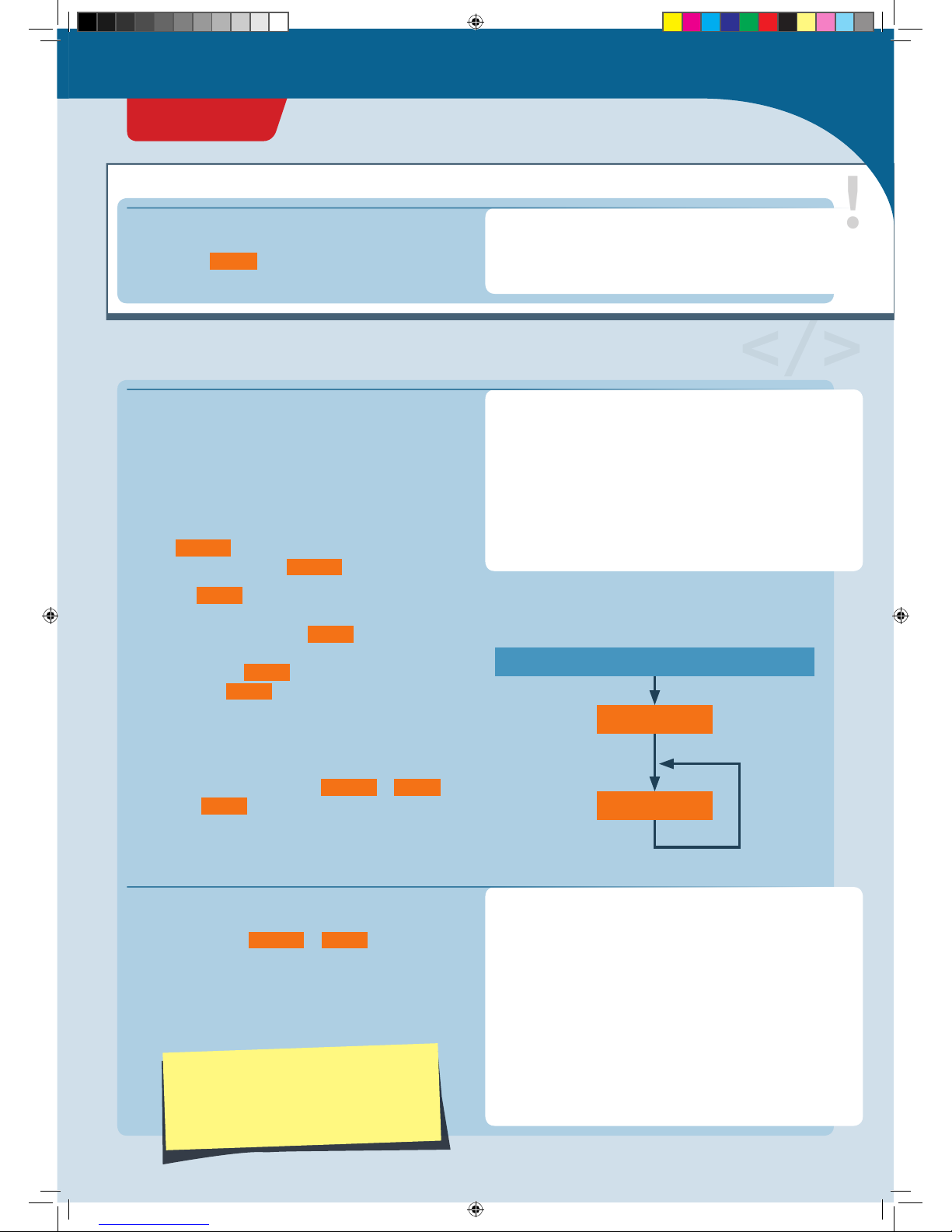
ARDUINO SWITCHED ON
That is the basic skeleton for every Arduino program:
1. Your KosmoDuino starts by processing all instructions
in the s e t u p () function, i.e., all functions written in the
curly brackets following s e t u p () .
2. Then, the l o o p() function is invoked. That means that
your microcontroller executes all instructions written in
the curly brackets following l o o p() . Once the final
instruction has been processed, your controller once
again invokes the l o o p() function. In other words, the
instructions in l o o p() are invoked over and over in an
endless loop. That is why it’s called a loop function.
You can visualize this idea a little more clearly in a flow
diagram. The program always proceeds in the direction of
the arrows: from switching on, to s e t u p() , to l o o p () and
then back to l o o p() again and again.
You could upload this program right away to your
KosmoDuino if you wanted. But since there are no
instructions in either s e t u p () or l o o p() , the program
wouldn’t do anything.
So why not give your KosmoDuino something to do? Try
changing the program code like this:
▲Flow diagram
In the field of Arduino programming, the
term “sketch” is often used to refer to a
program. In this instruction manual, both
terms will be used.
This is where the explanation for the program code is
written. Portions taken from the code are always
highlighted in orange .
PROGRAM CODE EXPLAINED:
Here is where the program code is written
// Comments on the code are always in gray.
// This text is not a functional part of the
// code. It provides explanation and clarity.
Your first program: Blink!
</>
!
CodeGamer
PROJECT 1
CodeGamer manual inside english.indd 9 7/19/16 12:31 PM

</>
To upload a sketch to your KosmoDuino, proceed as
follows:
1. Connect the KosmoDuino to your computer with the USB
cable. You will not need the interaction board.
2. Save your program code if necessary. To do that, click
on the “save” symbol in the Arduino environment.
3. Make sure that the correct board is selected:
Tools ➜Board ➜“Arduino/Genuino Uno.”
4. Make sure that you have selected the correct port:
Tools ➜Port ➜e.g., “COM3” (Arduino/Genuino Uno).
5. Now click on the “upload” symbol in the Arduino
environment.
Don’t let yourself be intimidated by all the strange terms and brackets! We will go through the program step by step. You
will soon see that it isn’t hard to understand at all!
But before we can see what the program does, we have to upload it to
the KosmoDuino. Follow the instructions below to learn how to do this.
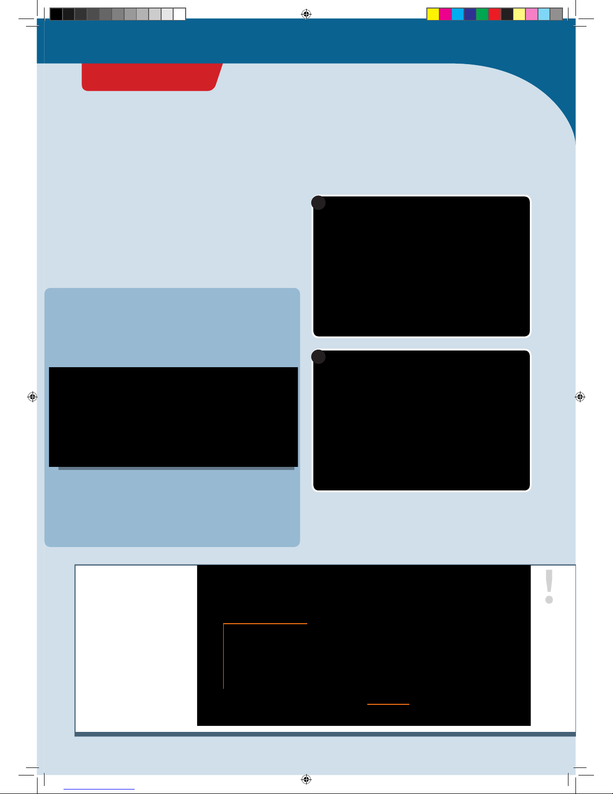
New Open
Upload
Save
Status line Window for further
explanations
Verify
If you did everything correctly, the following messages
should appear in sequence in the status line:
1. Compiling sketch …
2. Uploading …
3. Uploading completed.
Compiling sketch
…
Uploading
…
Uploading completed.
UPLOADING A PROGRAM TO KOSMODUINO
You can only ever upload one program at a time to
your KosmoDuino. If you want to play the KosmoBits
game with your gamepad, you will have to install the
KosmoBits_App.ino file. This file comes pre-installed
on your KosmoDuino when your kit is shipped.
PROJECT 1
CodeGamer manual inside english.indd 10 7/19/16 12:31 PM

!
ERROR MESSAGE?
If you see an error message, take a careful look at the
program text you entered. Is it possible that you wrote
something incorrectly? The place where an error leads to
problems in the program text is marked in red in the
Arduino environment (see illustration). In any case, you
should try looking for the actual error first. Even just tiny
typos will lead to error messages! If you cannot find an
error, then take a look at the yellow box below. There,
under the “Opening the sample programs” heading, you
will find an explanation of how you can use the example
programs described in this manual without having to type
them into the computer from scratch.
Typo: “pinnMode” instead of “pinMode!” The
location of the error is highlighted in red. ▶
BlinkOnBoard.ino: In function 'void setup()':
BlinkOnBoard:11: error: 'pinnMode' was not declared in this scope
'pinnMode' was not declared in this scope
'pinnMode' was not declared in this scope Copy error messages
Did everything work? Great! If so, you will now see a little
green LED — the “onboard LED” — blinking on and off on
the KosmoDuino.
Opening the sample programs
All sample programs can be opened directly, so you can
bypass typing them in by hand. You will find them in the
Arduino environment in this menu:
File ➜Examples ➜KosmoBits
EXPLANATION
Now it’s time to really understand the program. Let’s take
a closer look at it.
The first line reads: int ledPin = 13;
In the Arduino programming language,
instructions must be closed with a
semicolon (“;”).
This defines a variable with the name ledPin . Variables
are important components of any program. You can save
any value you like in a variable — numbers, letters, or
entire words. Each variable has a name. The name allows
you to invoke the saved value whenever you like.
If you want to save a value in a variable, use the equals
sign (“=”). The variable goes on the left side of the equals
sign, while the value goes on the right. For example,
int ledPin = 13 means that the value 13 is saved in the
PROJECT 1
CodeGamer
CodeGamer manual inside english.indd 11 7/19/16 12:31 PM

void setup() {
pinMode(ledPin, OUTPUT);
}void loop() {
digitalWrite(ledPin, HIGH);
del ay(5 0 0);
digitalWrite(ledPin, LOW);
del ay(5 0 0);
}
Here, a function is defined. The function is called
s e t u p ()
.
When a function is invoked in the program code, all the
instructions contained in it are carried out step by step.
Those are all the instructions written between the curly
brackets. So you can think of a function as a small
sub-program.
The function s e t u p () , by the way, is a special function. It
is always the first thing that is automatically invoked
whenever you start your KosmoDuino.
But what does the s e t u p () function actually do? It
invokes another function: pi n M o d e() . This is the function
that allows you to specify the operating mode in which a
pin is going to work. In this case, the ledPin (pin number
13) is to work as OUTPUT , or the output pin.
An output pin works like a switch that you turn on or off
as determined by the program. You will learn about the
other possible operating modes in later projects.
If the instructions in s e t u p () have been processed by
your KosmoDuino, the next thing to be invoked is the
l o o p() function. Let’s take a look at what this function
contains:
!
FUNCTIONS
Functions allow you to divide up your programs into smaller blocks. That can help you keep a clear overview, and it
promotes order in the program. Also, you can pack frequently used sequences of instructions into a single function.
Instead of repeating the same text in the program code every time, you can simply invoke the corresponding function.
Just as with the definition of a variable, to define a function you have to start with an example. In this case, let’s take
void .
This is the so-called return type. A function, in other words, can end by returning a value to the program that invoked it.
In this case, the return type is void , meaning “empty.” In other words, this function returns no value at all! An example
of a value that might be returned is the temperature measured by a sensor.
Important: Always give your functions a name that conveys what the function does. That will help you understand the
program when you’re reading it.
variable ledPin . The way you say it is: “The value 13 is
assigned to the variable ledPin .”
Wherever you want to use the number 13 in your program,
you can now write “ledPin” instead of “13.”
BUT WHAT DOES int MEAN?
In the Arduino programming language, a variable cannot
take just any value you like. The values must be of a
certain type that has to be determined. In this case, the
type is int . That means that the variable can take a so-
called integer value.
For your KosmoDuino, those values are the whole numbers
from -32768 to 32767.
PROJECT 1
CodeGamer manual inside english.indd 12 7/19/16 12:31 PM
What happens when l o o p() is invoked? The first
instruction in l o o p () is:
digitalWrite(ledPin, HIGH);
You can use digitalWrite() to control whether voltage
is applied to an output pin or not. When issuing this
request, there are two things that you will have to
communicate to the digitalWrite() function:
1. Which pin is intended?
2. Should the voltage at the pin be switch on ( HIGH ) or
off ( LOW )?
In this case, voltage is switched on at pin number 13
(ledPin ), and the LED lights up!
If you want to switch on another pin, let’s say pin
number 9, you would write digitalWrite(9, HIGH); .
The next instruction is:
del ay(500); .
You can use the d e l ay() instruction to delay the program
sequence for a specific period of time — in other words, to
make it wait. The amount of time is determined by the
number that you assign with the request, in this case 500 .
The time is indicated in milliseconds (thousandths of a
second). 500 milliseconds is half a second. So the program
waits and does nothing for half a second.
Then we have the instruction
digitalWrite(ledPin, LOW); .
You can probably understand this one without any help.
Right — the LED is switched off again!
Then the KosmoDuino waits another half a second:
del ay(500); .
And then?
Then it starts all over again from the beginning! l o o p () is
a special function in the Arduino programming. It repeats
endlessly! All commands in l o o p() are carried out over
and over in an endless loop. This is known as the main
loop. This makes l o o p() the most important function in
any KosmoBits program. It controls what the KosmoDuino
actually does, while s e t u p () handles the required
preliminary steps.
You have already seen what happens when the main loop
is repeated: The LED is switched on and off, over and over,
in regular intervals of half a second. In other words — the
LED blinks.
!
TYPES A few common type specifiers and their meanings
TYPE MEANING VALUES
int Whole numbers or HIGH / LOW (on/off) -32,768 to 32,767
long Whole numbers, large -2,147,483,648 to 2,147,483,647
float
Floating decimal numbers: numbers with a
decimal point
e.g., 1.5; 3.141; 2.678
double Like float but with twice the precision e.g., 3.141964; 21.45873
char Individual letters e.g., a; A; c; C
const Unchangeable value Can take any values
PROJECT 1
CodeGamer
CodeGamer manual inside english.indd 13 7/19/16 12:31 PM
Off switch
In your first “blink” sketch, you learned how to use a
program to make an LED blink on your KosmoDuino. To do
that, you used a pin on your controller as an output pin to
make the LED switch on and off.
But you can also use a pin as an input pin. In this case, the
pin is not turning voltage on or off. Instead, the program
can tell you whether or not an electrical voltage is
supplied to the pin.
You can then use that to turn the LED on and off with a
simple switch.
YOU WILL NEED
›
KosmoDuino
›
male-male jumper wires (see explanation on p. )
PREPARATION
Attach one jumper wire to pin 9 and the other to one of the
GND pins. GND stands for ground or grounding. These pins
have no actual function beyond conveying current.
int ledPin = 13;
int switchPin = 9;
int switchValue = HIGH;
void setup() {
pinMode(ledPin, OUTPUT);
pinMode(switchPin, INPUT_PULLUP);
}
void loop() {
switchValue = digitalRead(switchPin);
digitalWrite(ledPin, switchValue);
del ay(5 0);
}
THE PLAN
Upload the sketch to your KosmoDuino as described on
page 10. After uploading, the LED will light up. If you then
bring the two free jumper wire contacts together and
make them touch, the LED will stop shining.
THE PROGRAM
So what does the program do?
int ledPin = 13;
int switchPin = 9;
int switchValue = HIGH;
You will first have to define three variables:
• ledPin for the pin to which the LED is connected.
• switchPin should be assigned the value 9, because you
will be connecting your “switch” to pin 9.
• switchValue will start by getting the value HIGH .
Later on, you will “read out” pin 9 and save the readout
value in switchValue .
PROJECT 2
Warning! Not suitable for children under 8 years.
There is a risk of hot surfaces of components on the
PCB (printed circuit board) when different polarities
are incorrectly short-circuited or the capacitor is
subject to fault conditions.
CodeGamer manual inside english.indd 14 7/19/16 12:31 PM
void setup() {
pinMode(ledPin, OUTPUT);
pinMode(switchPin, INPUT_PULLUP);
}
void loop() {
switchValue = digitalRead(switchPin);
digitalWrite(ledPin, switchValue);
del ay(5 0);
}
</>
This is almost the same as in your first program. The
ledPin is operated as an output pin ( OUTPUT ). Pin 9
(switchPin ), on the other hand, is operated as an input
pin. So in the p in M o d e () instruction for switchPin ,
instead of the value OUTPUT , you will use INPUT_PULLUP .
First, use digitalRead(switchPin) to read out the
current state of pin 9. If the pin is electrically connected to
a “GND” pin, it yields the value LOW . That means that
there is no voltage supplied. Otherwise, it yields the value
HIGH . Save this value in the switchValue .
Then, write this value into the LED pin. So if pin 9 is
connected to the GND pin, it switches off the LED.
Otherwise, the LED will be switched on.
Finally, d el ay(50) will make you wait briefly before the
entire sequence repeats.
On switch
YOU WILL NEED
›
KosmoDuino
› male-male jumper wires
PREPARATION
Connect one jumper wire to pin 9, and the other to one of
the GND pins. int ledPin = 13;
int switchPin = 9;
int switchValue = HIGH;
void setup() {
pinMode(ledPin, OUTPUT);
pinMode(switchPin, INPUT_PULLUP);
}
void loop() {
switchValue = digitalRead(switchPin);
if(switchValue == LOW) {
digitalWrite(ledPin, HIGH);
} else {
digitalWrite(ledPin, LOW);
}
del ay(5 0);
}
THE PROGRAM
Upload the sketch to your KosmoDuino as described on
page 10. This time, after uploading, the LED will remain
dark. It only lights up when you touch the two free jumper
wire contacts together.
THE PLAN
In the previous project, you learned how to switch off an
LED with the help of a simple switch. But what do you do if
you want it to work in reverse — in other words, to have
the LED only come on if the contact is closed? Just change
the program!
PROJECT 3
CodeGamer
Warning! Not suitable for children under 8 years.
There is a risk of hot surfaces of components on the
PCB (printed circuit board) when different polarities
are incorrectly short-circuited or the capacitor is
subject to fault conditions.
CodeGamer manual inside english.indd 15 7/19/16 12:31 PM

EXPLANATION
Let’s just take a look at the
l o o p()
function, because that’s the only
place where anything was changed relative to the “off switch” program.
void loop() {
switchValue = digitalRead(switchPin);
if(switchValue == LOW) {
digitalWrite(ledPin, HIGH);
} else {
digitalWrite(ledPin, LOW);
}
del ay(5 0);
}
Just as with the “off switch,” you start by reading out the
switchPin and saving the current value, i.e., HIGH or
LOW in the switchValue variable.
But you do not want to write the read value into the LED
pin — just the opposite: When switchValue has the
value of LOW , you want to switch on the LED
(digitalWrite(ledPin, HIGH) ); otherwise, you want to
switch off the LED ( digitalWrite(ledPin, LOW) ).
In the program text, you express that with
if (...){...} el s e {...} . Note the “if” and “else.” You
guessed it — this lets you use the program to respond to
different conditions.
The condition to which you are responding here is
switchValue == LOW . You can understand that as a
question: “Is the switch value equal to LOW?” You can
evaluate the answer to that with the if() instruction: If
the switchValue is equal to LOW
(if(switchValue == LOW) ), the program code in the first
pair of curly brackets is carried out:
digitalWrite(ledPin, HIGH) . The LED is switched on.
Otherwise ( else ) the part in the second pair of curly
brackets is carried out: digitalWrite(ledPin, LOW) . The
LED is switched off.
Finally, d el ay(50) will make you wait briefly before the
entire sequence repeats.
</>
!
JUMPER WIRES
Jumper wires serve as an easy way to connect electronic
components to each other. In this experiment kit, you will
find two different types: male-male and male-female.
They really are called that! “Male-male” means that there
is a wire on both ends. While “male-female,” on the other
hand, there is a wire on one end and a socket on the other.
Jumper wires are sometimes also called patch cables.
»Female End« »Male End«
PROJECT 3
CodeGamer manual inside english.indd 16 7/19/16 12:31 PM
The Interaction Board
OK, we admit it. Making a little LED light up is not very
exciting. Still, it helped to give you a quick introduction to
programming your KosmoDuino.
To help you learn how to do more exciting things with
your microcontroller as quickly as possible, we have
developed the interaction board. You may have gotten to
know it a little already while playing the CodeGamer
video game. It has several very practical components that
will come in handy for lots of projects:
To work with the interaction board, you will first have to
insert your KosmoDuino into the board’s pin socket (see
illustration).
!
NOTE!
To upload a program to the
microcontroller, you will
insert the USB cable into
the USB port on the
KosmoDuino. The USB
terminal on the interaction
board is only for charging
the battery.
1
2
Upload
program Charge battery
• Two buttons (“button 1” and “button 2”)
• A multicolored LED (“NeoPixel”)
• A rotating wheel (“rotary encoder”)
• A speaker (“buzzer”)
And most important:
• A socket for connecting the KosmoBits sensors
(temperature, motion, brightness, loudness)
• A battery so that you can also use your
KosmoDuino when it isn’t attached to a computer.
Then you’ll be ready to start! In the following projects,
you will start by exploring the interaction board’s
capabilities, and then move on to the more complex
projects.
CodeGamer
INTERACTION BOARD
CodeGamer manual inside english.indd 17 7/19/16 12:31 PM
Colored light
YOU WILL NEED
› KosmoDuino in the interaction board
THE PLAN
On the interaction board, you will find a multicolored LED
called a NeoPixel. It’s a kind of LED that lets you decide
what color and brightness level you want it to have. This
Up to now, you have only learned about variables that act
as containers for numerical values. The pixel variable
that you are defining here is a little different: Instead of
numbers, it serves as a container for an object of the
KosmoBits_Pixel type. That sounds more confusing than it
really is. It just means that objects can be more than
simple values such as int .
More specifically, rather than just having one value, they
can bring their own functions with them. These are also
known as methods. Your pixel , for example, is an object
that you can use to control the NeoPixel on your
interaction board. For that purpose, it has a method by the
name of setColor() , that you can use to adjust the color
and brightness of the NeoPixel. Next, in the main loop, you
will learn how this works.
To adjust the color and brightness of your NeoPixel, you
will need four number values — one for the brightness
and three for the primary colors red, green, and blue.
These values will be saved in the corresponding
variables red , green , blue , and brightness .
The various colors will be produced by mixing these three
basic colors. You will be setting the corresponding
number value to determine how strongly each of the
colors in this mixture will be represented. You can use
values from 0 to 255. 0 means that the corresponding
color will not light up at all. With a value of 255, the
color will shine with the highest possible brightness.
KosmoBits_Pixel pixel;
#include <Adafruit_NeoPixel.h>
#include <KosmoBits_Pixel.h>
int red = 0;
int green = 0;
int blue = 0;
int brightness = 0;
Here’s something new to you. The
#include
instruction
will let you include code from other programs in your
program. In this case, you will be including content from the
“Adafruit_NeoPixel.h” and “KosmoBits_Pixel.h” files
.
You will always have to insert these two lines at the
beginning of your program when you want to use the
NeoPixel!
Multicolored NeoPixel LED
THE PROGRAM
little project will show you how it works, and how to get
your NeoPixel to shine in all sort of colors
</>
PROJECT 4
CodeGamer manual inside english.indd 18 7/19/16 12:31 PM
Table of contents
Popular Game manuals by other brands


Haba
Haba My Very First Games First Orchard manual

Hathaway
Hathaway FAIRMONT NG2574 Assembly instructions

Enabling Devices
Enabling Devices Batter Up 1433 user guide

Fundex Games
Fundex Games Sonic Search User instructions

Newgy Industries
Newgy Industries Pong-Master owner's manual

Mattel
Mattel Pictionary Air Kids VS. Grown-Ups manual


