GD3 1200
This model has one
gas injector at the
right hand side of
the burner tray.
•Install the burner tray by carefully
lowering the end opposite from the pilot
meanwhile holding up the pilot end,
lower the burner tray down and move
towards the pilot in one movement.
•Ensure the burner tray is located
correctly into the burner bracket and the
jets are aiming into the burner tube inlet
holes.
•Replace the stainless steel burner end
caps (2 x screws on each cap) at either
end of the burner.
• Install the burner tray by carefully lowering the end opposite from
the pilot meanwhile holding up the pilot end, lower the burner tray
down and move towards the pilot in one movement.
• Ensure the burner tray is located correctly into the burner bracket
and the jets are aiming into the burner tube inlet holes.
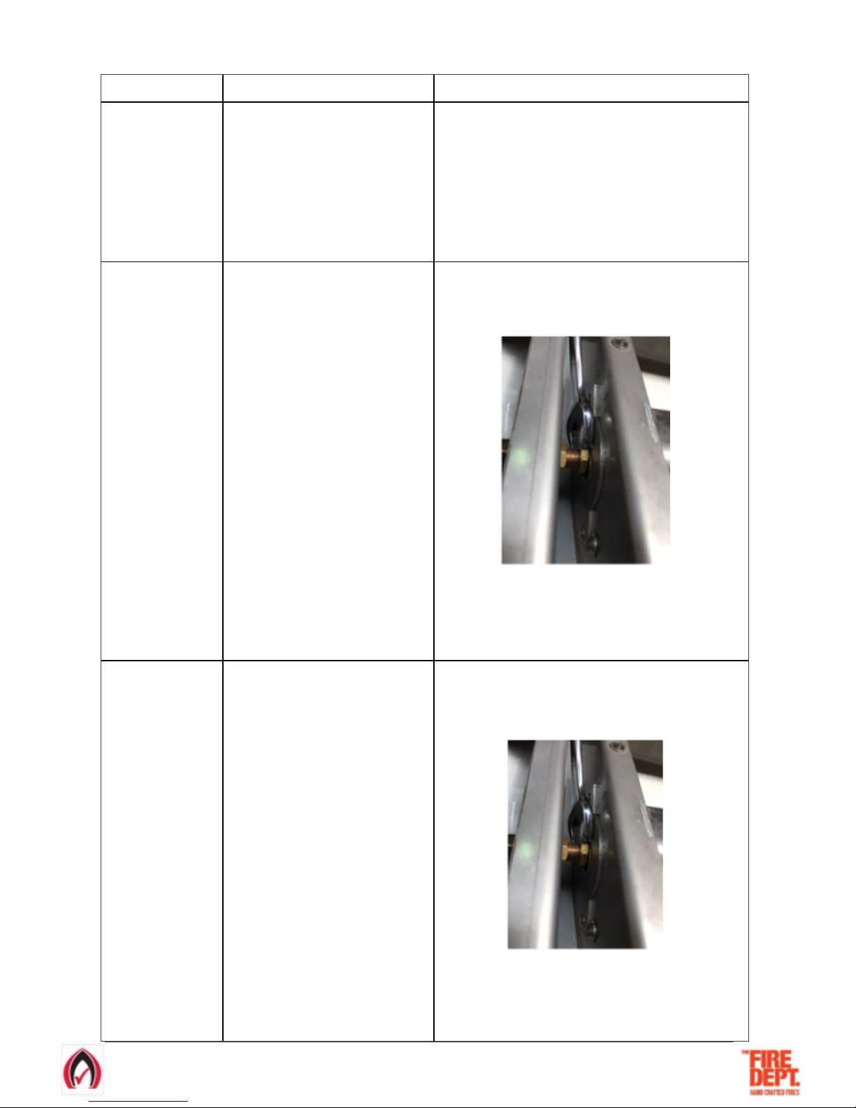
• On the left hand side gas injector, gently tighten (do not
overtighten) the 12mm brass nut closest to the burner tray.
• Replace the stainless steel burner end caps (2 x screws on each
cap) at either end of the burner.
GD3 1500
This model has two
gas injectors at the
right and left hand
sides of the burner
tray.
• Install the burner tray by carefully lowering
the end opposite from the pilot meanwhile
holding up the pilot end, lower the burner
tray down and move towards the pilot in
one movement.
• Ensure the burner tray is located correctly
into the burner bracket and the jets are
aiming into the burner tube inlet holes.
•Replace the stainless steel burner end
caps (2 x screws on each cap) at either
end of the burner.
GD3 1600
This model has two
gas injectors at the
right and left hand
sides of the burner
tray.
• Install the burner tray by carefully lowering
the end opposite from the pilot meanwhile
holding up the pilot end, lower the burner
tray down and move towards the pilot in
one movement.
• Ensure the burner tray is located correctly
into the burner bracket and the jets are
aiming into the burner tube inlet holes.
•Replace the stainless steel burner end
caps (2 x screws on each cap) at either
end of the burner.
• Install the burner tray by carefully lowering the end opposite from
the pilot meanwhile holding up the pilot end, lower the burner tray
down and move towards the pilot in one movement.
• Ensure the burner tray is located correctly into the burner bracket
and the jets are aiming into the burner tube inlet holes.
• On both the left and right hand gas injectors, gently tighten (do not
overtighten) the 12mm brass nuts closest to the burner tray.
LH Gas Injector RH Gas Injector
• Replace the stainless steel burner end caps (2 x screws on each
cap) at either end of the burner.
Burner Tray Installation Process
21-3-2017 VERSION 4 Page of 720
• Install the burner tray by carefully lowering the end opposite from
the pilot meanwhile holding up the pilot end, lower the burner tray
down and move towards the pilot in one movement.
• Ensure the burner tray is located correctly into the burner bracket
and the jets are aiming into the burner tube inlet holes.
• On both the left and right hand gas injectors, gently tighten (do not
overtighten) the 12mm brass nuts closest to the burner tray.
LH Gas Injector RH Gas Injector
• Replace the stainless steel burner end caps (2 x screws on each
cap) at either end of the burner.