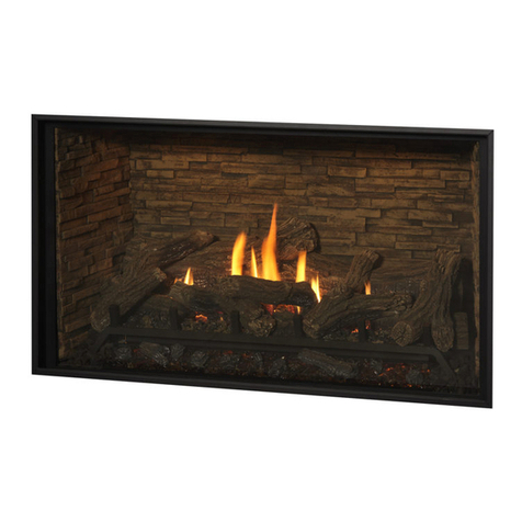
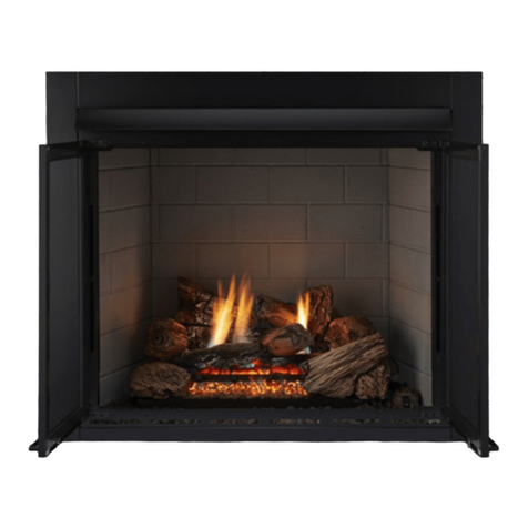
The Fire Dept WD6 User manual

WD6 Open Fire - Wood Burners
Installation Instructions for Installing into Framing
WD6 800 mm OPEN FIRE
Visit www.thefiredept.co.nz for Spec’s, DWG’s and PDF uploads of Fires
Fire, Flue System and Instructions to Comply with ASNZS 2918:2001
Keep these Instructions for further reference……Ensure that you have the correct and current Installation details for the The Fire Dept.
Installation
The Fire is to be Installed by a Certified NZHHA Installer or an Approved NZHHA Installation Technician.
See www.homeheat.co.nz/members for a Certified NZHHA SFAIT Installer in your area .
IMPORTANT
Read all the Instructions carefully before commencing the Installation. Failure to follow these instructions may result in a fire hazard and void the warranty

Location of the Fire. Open fires are better located at one end of a room or area, as they project the heat away from their opening.
The Topography of the land .
The slope and position of the land in relation to the home has a bearing on how the wind will interact with the fire and flue system.
Care needs to be taken to ensure that the flue termination is in the correct position to maximise performance.
The Prevailing Wind.
Care needs to be taken to ensure that the flue termination is in the correct position as wind and gusts that hits the flue and cowl sys-
tem may overcome the cowl and draft back down the flue into the home. This can be a combination of down draft and high pressure.
Hearth and Plinth:
The Height of the Hearth off the Floor. The Finishing that is to be used on the Hearth is to be allowed for at the design stage.
Note : Ensure Air Intake at Base of Firebox is not blocked or restricted .
Positioning of the Flue System:
There is a maximum distance that an offset flue can be Installed . Reference to AS/NZS 2918:2001 .
Flue And Fire Clearance:
To be maintained to the Manufactures Instructions &/or Comply with appropriate Standards & Building Codes .
Pressure Differential, Venting & External Air into the Building :
All fires need air to burn and draw correctly, Kitchen Fans, Air Conditioning units, High Wind Zones, Naturally forming Draft spaces,
can all have an effect on the pressure difference from inside the building to the outside. A lower pressure in the building may induce a
draft down the flue system and back into the building causing the fire to smoke or spill into the building. Care needs to be taken at
the design and installation stage to adequately vent the building, or some mechanical system to ensure that there is always a
neutral or positive pressure at the fireplace and a negative pressure at the flue outlet. This will ensure that the draft in the flue
system is always to the outside.
Wind Noise:
You may encounter wind noise in some installations. It is recommended to use an enclosed chase with a chimney pot
to help reduce noise. There will always be some noise from the flue systems of all fireplaces.
Prior to Construction and Installation Important Notes:
Install to Manufacture’s Specifications as tested.
Install also to AS/NZS 2918:2001for further situations.
All new Installations require a permit.
For special requirements concerning materials (timber mantle and surrounds) within close proximity of “The Fire Dept” products,
please contact your local “The Fire Dept” Technical Consultant.
Stage 1: Frame Construction Procedure by Builder.
Mark out Flue centre.
Mark out Framing Clearance requirements.
Can also Construct plinth only, to required height.*
Stage 2: Install Procedure by Certified NZHHA only or see www.homeheat.co.nz go to “members & follow Instructions to
Get a Certified NZHHA SFAIT Installer .
Install Plinth & Zero Clearance Heatshield Sides, Back & Top.
Install Firebox in place & Fit Gather to Firebox.
Install Top Front Heatshield Panel & Seal top join.
Install Hearth (if included).
Fit Flue System & Flashing System with Vented Cowl & Cone System.
Stage 3: Finishing Procedure by Builder.
Construct Hearth to required thickness (if not already Install)
All WD6 Fires require Etapan to be Lined Above (2400mm Stud) & to the Sides (200mm either side of Firebox opening)
DO NOT use 10mm Fireline ,Gib or any other Combustible Lining product in this area other than Etapan as tested for lining.
Note: A SFAIT Certified Installer generally Install’s Hearth and Plinth unless otherwise discussed.
Ensure that the Fire and Flue System is swept annually or more frequently if required.
To Sweep Flue and Clean Firebox:
Cover front of fire with sheets.
Remove cowl from top of chimney.
Sweep from the top, down the flue.
Remove all soot and ash.
INSTALLATION ORDER OF OPERATIONS
POINTS TO CONSIDER PRIOR TO INSTALLATION
Due to continued product improvement, The Fire Dept. reserves the right to change product specifications without prior notification.
All Dimension are in mm….. Date Created : 16/09/14

Due to continued product improvement, The Fire Dept. reserves the right to change product specifications without prior notification.
All Dimension are in mm….. Date Created : 16/09/14
FIREBOX WD6 800mm
A 620mm
B 800mm
C 534mm
D 670mm
E 900mm
F 508mm
G 815mm
H 482mm
I 400mm
J 75mm
K 300 Dia
L 355mm
THE FIRE DEPT - FIREBOX DIMENSIONS
WD6’S UNIQUE GATHER DESIGN HAS AN
ADJUSTABLE BAFFLE INSIDE THE GATHER,
THIS CAN ADJUSTED FORWARD (CLOSED)
OR BACK (FULLY OPEN) WHICH ALLOWS
FOR CONTROL OF DRAW WHEN FIRE IS IN
USE.
THE FIRE DEPT - FIREBOX GATHER
This is a general Installation guide only –Contact a “NZHHA Installer” for Installation Advice.
See : www.homeheat.co.nz , choose “members” & pick your Area & Fire type (wood / Gas etc) this will provide
you with a NZHHA Certified Installer (use the SFAIT Installers Only .)

1. All the Dimensions are minimums.
2. Fit the Plinth into position in the Cavity. The Insulating Plinth (75mm Celcrete) should have a 25mm Air-
gap using Top Hats Supplied & fitted as per specifications in following pages. The Plinth is designed to
be elevated to allow for Finishing on the Hearth (25mm Max).
3. Assemble Back, Sides & Top Panels of the Heat Shield, position into Cavity.
4. Fit the Firebox into the Cavity, allow for the Surrounding Fascia to be Flush with Timber Framing. Fix the
Firebox down through the Base of the Fire (under the Ashpan) to the Plinth &/or through into the floor.
(Seismic Restraints).
5. Fit the Gather onto the Firebox. Bolt into position with the Bolts in the Left and Right Hand Sides of the
upper insides of the Firebox, then fit the Top Front panel of the Heatshield & fix in place..
6. Install the Flue System Supplied (The first flue section supplied is a 600mm Vented Combo Kit, this must
be fitted first before the Min 2x 1200mm Lengths of Flue are fitted as tested).
7. All WD6 Fires require 10mm Etapan Lining (Do not use Gib or Fireline) as a Lining on the wall around &
above the Fire to Minimum height (1110mm) & to within 200mm either Side of the Fire (in line with edge of
Hearth.
Date Created : 16/09/14
FIREBOX WD6 800mm
A 300 mm
B 1200 mm
C 1000 mm
D 25 mm
E 50 mm
F 600 mm
G 583 mm
H 75 mm
I 1072 mm
J 952 mm
K 120 mm
L 845 mm
THE FIRE DEPT - FIREBOX DIMENSIONS
Due to continued product improvement, The Fire Dept. reserves the right to change product specifications without prior notification.
All Dimension are in mm…..
This is a general Installation guide only –Contact a “NZHHA Installer” for Installation Advice.
See : www.homeheat.co.nz , choose “members” & pick your Area & Fire type (wood / Gas etc) this will provide
you with a NZHHA Certified Installer (use the SFAIT Installers Only .)
FRONT FACE OF FLANGE
TO SIT FLUSH WITH
FRAMING, WITH 10MM
ETAPAN AS LINING AS
PER STEP 7 BELOW

Date Created : 16/09/14
THE FIRE DEPT - FIREBOX IN FRAMING DIMENSIONS
Due to continued product improvement, The Fire Dept. reserves the right to change product specifications without prior notification.
All Dimension are in mm…..
This is a general Installation guide only –Contact a “NZHHA Installer” for Installation Advice.
See : www.homeheat.co.nz , choose “members” & pick your Area & Fire type (wood / Gas etc) this will provide
you with a NZHHA Certified Installer (use the SFAIT Installers Only .)
FIREBOX WD6 800mm
A 963 mm
B 1052 mm
C 635 mm
D 450 DIA
E 300 mm
F 1200 mm
* G 1110 mm Min.
H 450 mm
I 450 mm
IMPORTANT NOTE :
FRAMED CAVITY MUST BE VENTED AT THE
BOTTOM THROUGH INTERNAL & EXTERNAL
WALLS USING 4X 100MM VENTS & VENTING
AT THE TOP THROUGH THE S/S FLASHING
CAP OR THROUGH 2X 100DIA VENTS ON
THE TOP SIDES OF THE CHIMNNEY CHASE.
10mm ETAPAN MUST BE USED UNDER
FLASHING.
BOTTOM CAVITY
VENTING HERE
BOTTOM CAVITY
VENTING HERE
TOP VENTING
THROUGH
S/S FLASHING
SPIGOT
Table of contents
Other The Fire Dept Indoor Fireplace manuals
Popular Indoor Fireplace manuals by other brands

baltur
baltur GI 500 ME Original instructions

Town & Country Fireplaces
Town & Country Fireplaces D Series installation manual

Rocal
Rocal Ronde Central X1345 user guide

Continental Refrigerator
Continental Refrigerator Builder Series Installation and operation manual

Majectic
Majectic SC36A Homeowner's installation and operating manual

RAIS/attika
RAIS/attika Q-Tee II GAS user manual