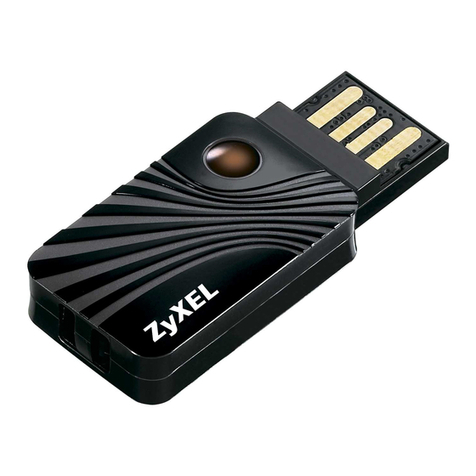
The Fisher MPX-100 Installation guide


THE
FISHER
MPX-100
UNIVERSAL
Stereophonic Multiplex Adaptor
L
T
HE
FISHER
MPX-100
is designed to adapt your FM-AM or FM
tuner to receive multiplex broadcasts in full stereophonic sound.
The experience gained from years of leadership in the design and
manufacture of FM tuners has been applied to the design of the
MPX-100
and has made it the best performing and most convenient
multiplex adaptor
111
existence. The exclusive FISHER STEREO
BEACON is a~~tontaticallyilluminated when you tune to a multiplex
program and turns off as soon as the station reverts to ordinary mono-
phonic transmission. At the same time, the FISHER Automatic Switch-
ing System senses whether the program transmitted is stereo or mono-
phonic and switches the
MPX-100
into the proper operating mode, thus
making it unnecessary to switch back and forth between stereo and
mono on your adaptor. Feedthrough connections for all types of tuners
arc provided, even when the
MPX-100
is turned off. Two separate
noi~cfilters can be operated by a single front panel sw~tch.One filter
oiTectb: the noise in the subcarrier only, thus providing full frequency
I
rewpoose; the other filter is designed to provide a steep roll-off al~ove
8
kc
lor reception of multiplex signals under more difficult conditions.
Most important of all are the careful attention to every detail of manu-
facture and the top-quality parts which have given FISHER products
r
a world-wide reputation for remarkable durability and outstanding
reliability.
INITIAL ADJUSTMENTS
11
FISHEII
tuners and receivers will give excellent results when.used
with the
MPX-100.
Your MPX-100 has also been designed to oper-
A'
ate with any tuner or receiver employing either a ratio detector or a dis-
criminator to demodulate the FM signal. Naturally, a multiplex adaptor
designed to operate perfectly with such a widc variety of tuners must be
provided with special controls. As a result of careful design and the use
of precision parts, however, it was possible to reduce the number of
controls on the
MPX-100
to only three: the Separation control on the
rear panel, and the Output Level controls also on the rear. The Separa-
tion control must be adjusted to provide the maximum degree of
stereo separation between channels for each particular model tuner.
In addition, two MPX input jacks are provided on the rear panel,
one to match tuners with low level outputs and the other to match
those with high outputs. These adjustments need be made only once,
when installing the
MPX-100.
(:otts~~lt
the Installation Guide on page
3
for the correct MPX
input jack and Separation control setting for your tuner. If your model
tuner is not listed, determine whether it employs a balanced ratio
detector. unbalanced ratio detector, or discriminator.

TABLE
OF CONTENTS
INSTALLATION GUIDE
FM
MULTIPLEX STEREO
PAGE
GENERAL INSTALLATION AND
OPERATION INSTRUCTIONS
5
INSTRUCTIONS FOR OWNERS
OF
FISHER TUNERS AND RECEIVERS
7
CUSTOM MOUNTING INSTRUCTIONS
9
Ratio DetectorTuners
The MPX output jack of all ratio detector tuners should be con-
nected to the LOW LEVEL input jack on the rear panel of the
MPX-100.
The Separation control on the
MPX-100
should be set at
3
for unbalanced ratio detectors and at 4 for balanced ratio detectors.
Discriminator Tuners
The Separation control of the
MPX-100
should be set at 4.5 for
all discriminator tuners.
If
the maximum output of the discriminator
(at the MPX output jack) is above
1.5
volts, connect the MPX output
of your tuner to the
HIGH
LEVEL input jack on the rear panel
of
the
MPX-100.
If
the maximum output is below
1.5
volts, connect the
MPX outj~utof your tuner to the LOW LEVEL jack.
NOTE:
If
your instruction manual does not contain this information,
you may have to contact your dealer or the manufacturer.
If
you find
it impossible to determine the maximum discriminator output of your
tuner, use
the
HIGH
LEVEL jack initially. Change to the
LOW
LEVEL
jack if the STEREO BEACON fails to light during a-multi-
plex transmission from a weak station.
120V
300W
MAX
I I
i
I
105-12OV
OUTPUT SEPARATION
OUTPUT LEVEL
L
@
ToTuNEa@Y$FL
MPX
OUTPUT
@
k%L
0

I
I
INSTALLATION
GUIDE
1
TUNER CONNECT TUNER
SET SEPARATION ~px
OUTPUT
10
MODEL
k
CONTROLAT: JACK MARKED
Fisher
FM-40
!
FMSO
P
FM-9O(X)
FM-100
FM-200
90-R
90-T*
.I
100-R
100-T
101-R
202-11
202-T'
TA-500'
5oo.S
600 (Serial No. below49999)
600 (Serial No. above 50000)
800
50-R**
70-RT**
EM***
80-T***
FM-80**
Altec-Lansing
306-A
I
!
-+
Bell
670
2421
2425
2441
3070
LOW LEVEL
LOW LEVEL
LOW LEVEL,
LOW LEVEL
LOW LEVEL
LOW LEVEL
LOW LEVEL
LOW LEVEL
LOW LEVEL
LOW LEVEL
LOW LEVEL
LOW LEVEL
LOW LEVEL
LOW LEVEL
LOW LEVEL
LOW LEVEL
LOW LEVEL
HlGH
LEVEL
HlGH
LEVEL
HlGH
LEVEL
HlGH
LEVEL
HlGH
LEVEL
4.5 HIGH
LEVEL
LOW LEVEL
HlGH
LEVEL
HlGH
LEVEL
LOW LEVEL
LOW LEVEL
CONNECT TUNER
TUNER SET SEPARATION
MPX
OUTPUT
TO
MODEL CONTROL AT: JACK MARKED
Bogen
3RB-40
SRB20
ST442
ST662
STP52
Grommes
Harman-Kardon
TA-260 (Festivalll)
TA-224(Recital)
T-230 (Sonnet)
T-220 (Aria)
ST360A (Madrigal)
FA-10 (Sonata)
F-10 (Tempo)
Citation
Ill
F500
Karg
CT-3
Mclntosh
HlGH
LEVEL
HlGH
LEVEL
HlGH
LEVEL
LOW LEVEL
HlGH
LEVEL
HlGH
LEVEL
LOW LEVEL
HlGH
LEVEL
HIGH
LEVEL
3
HlGH
LEVEL
HlGH
LEVEL
HlGH
LEVEL
HlGH
LEVEL
HlGH
LEVEL
HlGH
LEVEL
HlGH
LEVEL
LOW LEVEL
LOW LEVEL
4.5 HIGH
LEVEL
MR-55 4
LOW LEVEL
*Requires additionalstereoamplifier.
**Multiplex output jack must be added. See page
8
for instructions.
***Multiplex output jack mustbeaddedto early productionmodels.
See page
8
for instructions.

TUNER CONNECT TUNER
SET SEPARATION MpXOUTPUT TO
MODEL 'ONTRoL
AT:
JACK MARKED
Pilot
Realistic
1,
40-T
I
Scott
All
models
Sherwood
5-2000
4
5-2200
5-3000
5-7000
HlGH LEVEL
LOW LEVEL
4.5 HIGH LEVEL
FM MULTIPLEX
STEREO
LOW LEVEL
HlGH LEVEL
HlGH LEVEL
HlGH LEVEL
HlGH LEVEL
F
M
nRoADcAsrINc has a frequency range far in excess of the normal
hearing range. For example, Fisher wide-band tuners have a
frequency range which extends to
100
kc, while the normal hearing
range does not exceed 17 kc. This extra "space" in the frequency
response has now been put into service for the transmission of a
second and third signal sim~~ltaneouslywith the main carrier. The
third (and highest) signal is wed in commercial applications (for
background music) and will not be received on home high fidelity
equipment. The other two signals, however, are used for the recep-
tion of stereo programs. During multiplex broadcasts, the main car-
rier, which can be picked up by any
FM
tuner or receiver, contains
the sum or blended signal from both stereo channels (left plus right).
The second, snpersonic signal contains the information necessary for
stereo. This system makes it possible for an ordinary FM set to re-
ceive a fully balanced monophonic program during multiplex trans-
mission. At the same time, however, the circuits of the
MPX-100
separate the two stereo channels, thus providing you with a11 the added
benefits of full stereo sound.
Because
FM
multiplex requires new equipment and new techniques
at FM broadcasting stations, it is to be expected that not all pro-
grams will be of the same high technical calibre during the first few
months. Such occasional problems as may arise initially will no doubt
be solved quickly, as the stations gain experience with the new
procedures. It is important to keep in mind, however, that the stereo
subcarrier is inherently more noisy than the main carrier. In order
to receive weak or distant stations with acceptably low noise level%
you may find it necessary to change to an antenna with higher gain,
or to relocate your present antenna in a more favorable position.
If you have difficulty in receiving weak stations, the following
measures should be taken:
1-Reverse the antenna leads.
2-Reposition the
FM
Antenna.
If you are using
a
folded dipole
antenna, rotate it horizontally about its axis to determine the orienta-
tion which produces a null or minimum received signal as indicated
on the tuning meter or tuning eye. Then rotate the antenna
90
degrees
for the best position. The antenna should be as high as possible, hori-
zontal and away from all large metal objects and electrical wiring. It
may also be necessary to relocate the antenna to achieve a usable signal.
Indoor antennas, especially in metal frame buildings, will give improved
results when located close to outside windows.
%Change to Rooltop Antenna.
In extreme cases, where-an indo
antenna was used for monophonic reception, il may be necessary
change to an outdoor, rooftop antenna, or even
u
highly direction
yagi antenna. Directional antennas should be rotated for maximu
received signal strength.
Although the problems inhemtin
FM
multiplex have been stressed
it is not expected that they
will
arise very frequently. In general, th
can be solved simply by increasing the strength of the received sign
(and removing the distortion caused
by
multipath transmission)
through a change
in
the
antenna aptem,

GENERAL INSTALLATION
tuner
has
m
available
aexiliarp
pbww
auhI
an
mitemate
arraqm
AND OPERATION INSTRUCTIONS
-a
would
be
ta
wna~
the
YPX-Im
to
it,
and
con-
the
t-
te
h
smplih.)
HE
MPX-100
operates on
AC
only
at 105-120 volts. One three-
foot cable and two iour-foot cables are included to make con-
nections to associated equipment. Any additional connections should
be made with the same type of cable. Be sure to use the three-foot
cable for the connection from the MPX output jack on your tuner
since longer cable lengths will cause some loss of the higher fre-
quencies. Both.
MPX-100
outputs are low-impedance anode followers,
permitting cable lengths up to 10 feet between the
MPX-100
and
your amplifier. We recommend that you keep the
MPX-I00
right
beside your tuner (but away from power transformers) for ease of
operation and best performance.
NOTE:
Left (or
L)
designation corresponds to Channel
A;
Right (or
R) corresponds to Channel B.
ja&,
If
your
tuner
dw
#=tor
my
be
obtained
f
Installation
of the
"Yn
eonneetor
is
WITH
FM-AM
STEREO TUNERS:
.
and
tbglbr two plw
1-Connect the FM output of the tuner to the L INPUT jack on tho:
MPX-100.
(See Figure
1.)
W'TH
WM
MQMOPHBNJC
TUNERS?
1-'I%
taner
h4PX
autput
jack
should
be
connw%ad to either
the
3-The tuner MPX output jack should be connected to either the
LOW
LEVEL
or
HIGH
LEVEL
ja&
on the
rear
panel
ef
the
LOW
LEVEL or
HIGH
LEVEL jack on the rear panel of the
&PX-I&.
Refer
to
the
tsbb
0x1
page
3
(or
wnmlt the
mmufaaurer
MPX-100.
Refer to the table on page
3
(or consult the manufacturer
of
your tuner)
te
determine
the
jack
whid
Prlrzluld
be
4
for
this
of your tuner) to determine the jack which should be used for this conatetion.
Be
sure
bo
as
the
tlirmf~fg~
cabLe
supplied
with
the
ronnection.
Be
sure to use the three-foot
cable
supplied with the
%Connect the
Erlaia
tuner
eaiprtt
to
the
L
INPUT
jaek
en
the
&Connect the
L
(left) and R (right) outputs on the
MPX-100
to
IWX-ZOO.
If
art
additional
outpet
jack
(with
the
sams
led
outpa)
the corresponding Tuner input jacks on your stereo amplifier.
&Connect the power cable of the tuner to the auxiliary power outlet
on the rear panel of the
MPX-100,
and connect the power cable of ba~weenmonopbaic
and
sterm
the
MPX-100
to an auxiliary outlet on your stereo amplifier. (If your
3-Follow
step
6
and
5
far
FM-AM
stmw
tunem

Operation
THE
FISHER
0
POWER
eo,
STEREO
BEACON
UNIVERSAL
MULTIPLEX ADAPTOR
MODEL
MPX-100
STEREO-MONO
I
AUTOMATIC
TUNER
STEREO
OFo
*co
FF.O
UAL
NOISE
FILTER
SELECTOR
Figure
2.
Front
panel
of
the
MPX-100
INDICATOR LIGHTS:
The red Power jewel on the front panel glows
when power to the
MPX-100
is turned on. The green Stereo Beacon
automatically signals whenever the station tuned to is broadcasting an
FM stereo program. It will remain off during monophonic programs.
SELECTOR SWITCH:
The Selector switch has four positions:
AC
Off:
Power to the
MPX-100
is turned off, but feedthrough connec-
tions are provided from the tuner to the amplifier for monophonic FM,
..
AM or stereo FM-AM programs. You will find this position particularly
useful when listening to such programs for prolonged periods of time.
When switching from AC OFF to another position of the Selector
switch, it should be kept in mind that there will be a delay of approxi-
mately
30
seconds, due to necessary tube warmup, before the
MPX-100
will begin to operate.
Tuner:
In addition to providing the same feedthrough connections
from the tuner
to
the amplifier, this position places the Stereo Beacon
in operation. In the same manner as the
AC
OFF position, the tuner
signal passes directly through the
MPX-100,
completely unaffected by
the adaptor's internal circuitry. FM-AM stereo and FM or AM mono-
phonic programs may be heard directly from the tuner with the
Selector in this position. Whenever a multiplex FM stereo program is
broadcast, the Stereo Beacon will automatically light. However, FM
multiplex programs cannot be received stereophonically in the TUNER
position, nor will the Automatic Switching teature operate.
Stereo-Mono
Automatic:
This position is used for normal reception of
FM multiplex broadcasts in stereo sound, and, due to the FISHER
Automatic Switching System, may also be used for reception of
I
monophollic FM broadcasts. The Stereo Beacon will light whenever
4,
a multiplex program comes on the air, and the
MPX-100
will automati-
cally switch into the stereo mode. When the station reverts to mono-
phonic operation, the
MPX-10
will automatically switch to the mono-
phonic mode and the monophonic signal will appear at both outputs
of the adaptor. At the same time, the Stereo Beacon will be turned
off. This feature makes manual switching completely unnecessary
4
1
.1
4.
?
d

when an FM station alternates between monophonic and stereo selec-
lions. The mode selector of your amplifier should he left in the Stereo
position for
both
types of broadcast. If you live in a fringe area and
experience difficulty in receiving a particular program stereophoni-
c-ally, due
to
the high noise level, you may receive the program mono-
~jhonicallyby switching to TUNER or AC OFF. Since monophonic
reception is inherently less affected by background noise, the program
may be more enjoyable when this is done.
Stereo Manual:
This position should be used only during an FM
multiplex broadcast, when you wish to disable the Automalic Switching
System of the
MPX-100.
Although the Stereo Beacon will operate as
normally, the adaptor will
not
switch to the monophonic mode when
a monophonic program is broadcast. Under extremely rare circum-
stances, the background noise may interfere with normal operation of
the Automatic Switching circuits of the
MPX-100
(with the Selector
at STEREO-MONO AUTOMATIC). In this case, you can receive the
program stereophonically by turning the Selector to STEREO MAN-
UAL, or monophonically by turning to TUNER or AC OFF.
NOISE FILTER SWITCH:
The three positions of this switch perform
the following functions:
Off:
This position is used for normal reception of both monophonic
und multiplex stereo FM programs.
1:
This position should be used only on multiplex programs, when the
noise level is'higher than normal. Since this filter cancels noise only
in the stereo subcarrier (which is inherently noisier than the main
carrier), you will hear no difference in the frequency range of the
music, although stereo separation at the higher frequencies will be
lomewhat diminished.
2:
This filter, which provides a steep roll-off above
8
kc, operates in
the
name manner as the High
or
Scratch filter on your amplifier. To
nuppress noise on a muliplex program, try position
1
first. If more
noise suppression is desired, turn the Selector to position
2.
Thisfilter is
also quite effective in eliminating noise on monophonic FM programs,
iT
the Selector is in the STEREO-MONO AUTOMATIC position.
LEVEL SETS:
Two level sets are located on the rear panel for adjust-
ment of the sound level on both channels of the
MPX-100.
These
level sets should be adjusted so that no difference in volume is heard
when switching between
Tuner
and
FM
Stereo.
The volume level on
the feedthrough positions
(AC
Oj
and
Tuner)
is not affected by the
level sets.
INSTRUCTIONS FOR OWNERS OF FISHER
TUNERS
AND
RECEIVERS
NOTE:
Left (oiL) designation corresponds to Channel
A;
Right (or
R) corresponds to Channel B.
FM-40, FM-50, FM-90(X), 90-R, FM-100, FM-200, 202-R, 100-R:
Follow the appropriate instructions given in the preceding section.
7
Both MAIN and REC outputs should be connected to the
MPX-100.
600
and
800
1-Connect the MPX output of the receiver to the LOW LEVEL
jack of the
MPX-100.
Use the %foot cable supplied.
2-Connect the
L
and R OUTPUTS of the adaptor to the MPX Chan-
nel A and Channel
B
inputs of the
600
or
800.
%Turn both level sets on the receiver marked MPX A and MPX
B
to the maximum clockwise position.
&-To listen to FM, AM and FM-AM, operate as usual. To listen
to MPX stereo: Turn the Selector switch to FM-MPX position;
Mono-Stereo switch to STEREO, and
MPX-100
Selector switch to
STEREO-MONO AUTOMATIC.
500-S
1-Connect the MPX output on the receiver to the LOW LEVEL
jack of the
MPX-100.
Use the %foot cable supplied.
2-Connect the
L
and
R
outputs of the
MPX-100
to the MPX Chan-
nel
A
and Channel
B
inputs of the
500-S.

&To listen to FM, AM or FM-AM, operate as usual. To listen to
MPX stereo: Turn the
500-S
Selector switch to MPX and the Selec-
tor switch on the
MPX-100
to STEREO-MONO AUTOMATIC. This
arrangement will also permit reception of monophonic FM.
100-T
1-Connect the MPX output on the tuner to the LOW LEVEL
jack of the
MPX-100.
Use the 3-foot cable supplied.
2-Connect the
L
and
R
OUTPUTS to the Channel
A
and
B
AUX
inputs of the
100-T.
&Tune as no~malto the FM station desired (Selector switch in
FM position) and then switch to AUX STEREO to listen to multi-
plex stereo or monophonic FM programs
through
the
MPX-100.
Monophonic FM programs may be heard
directly
by switching to the
FM position on the
ZOO-T.
202-1
1-Connect the MPX output on the tuner to the LOW LEVEL
jack of the
MPX-100.
Use the %foot cable supplied.
2-Connect the L and R outputs to the Channel A and
B
AUX
inputs of the
202-T.
&To listen to multiplex stereo, tune as normal to the desired station
(Selector in TUNER position)
;
then turn the Selector to AUX and
the Mono-Stereo switch to STEREO. For monophonic FM broadcasts,
operate as usual.
101
-R
1-If you do not wish to listen to FM-AM
stereo
broadcasts, connect
both MON outputs on the
101-R
to the L and R inputs on the
MPX-100,
and the MPX output to the jack on the adaptor marked
LOW LEVEL. Then connect the L and R OUTPUT jacks of the
MPX-100
to the corresponding Tuner inputs on your amplifier.
2-If FM-AM stereo programs are broadcast in your area, connect
the STEREO FM output on the
101-R
to the L input on the adaptor,
the STEREO AM output to the adaptor
R
input and the MPX output
on the
101-R
to the adaptor jack marked LOW LEVEL. Then
connect the
L
and
R
OUTPUT jacks of the
MPX-100
to the corre-
sponding Tuner inputs on your amplifier.
&The first installation method enables you to choose FM, AM or
FM stereo multiplex. The Mode Selector on your amplifier should
be left in the Stereo position for all three types of broadcast. The
Selector on the
MPX-100
should be in the STEREO-MONO AUTO-
MATIC position for multiplex programs.
4-The second installation method permits reception of FM, AM,
FM-AM stereo and FM multiplex stereo. For FM reception: turn
the amplifier Mode Selector to Channel
A,
the
MPX-100
Selector to
TUNER and the tuner Selector to FM-AM. For AM reception: turn
the amplifier Mode Selector to Channel
B,
the
MPX-100
Selector to
TUNER and the tuner Selector to FM-AM. Use the same settings for
FM-AM stereo, with one exception: the amplifier Mode Selector should
be in the STEREO positio;l. For FM multiplex stereo, turn the
MPX-100
Selector to STEREO-MONO AUTOMATIC.
90-T
1-Connect the MPX output of the
90-T
to the LOW LEVEL
jack on the adaptor. Then connect the RCRDR output of the tuner
to the L input of the
MPX-100.
!&Connect the L and
R
outputs of the
MPX-100
to the correspond-
ing amplifier inputs marked TUNER.
3-Monophonic FM or stereo multiplex FM can both be received by
leaving the
MPX-100
Selector in the STEREO-MONO AUTOMATlC
position and the amplifier Mode Selector in
the
STEREO position.
For AM reception, turn the amplifier Mode Selector to Channel A.
50-R, 70-RT, 80-R,
80-1,
FM-80
Although Models FM-80, 50-R and 70-RT, and early production
models of the 80-R and 80-T are not
equipped
with
multiplex output
jacks, these tuners can easily
be
adapted
for multiplex by adding a
standard RETMA phono jack to
the
chassie close to the 6AL5 tube
socket. This jack is conneoted through
a
.01
mfd,
250V capacitor to

Pin
5
of the
6AL5
tube on the 50-R and 70-RT and Pin
1
of the
6AL5 tube on the 80-R, 80-T and FM-80. The 3-foot cable supplied
with the MPX-100 should be used to connect this jack to the jack on
the MPX-100 marked HIGH LEVEL. Feedthrough.connections should
be
made from the main outputs of these units to the
L
and R INPUT
jacks en the MPX-100.
Custom
Electra
(E-44)
1-Connect the MPX output of the Custom Electra to the LOW
LEVEL jack on the MPX-160. Then connect the
L
and
R
outputs
of the MPX-IOO to the AUX STEREO inputs on the
Eleccra.
2-To listen to monophonic FM,
AM
or stereo
FM-AM,
operate as
usual. To listen to stereo FM multiplex: turn the Elsatra Selector
switch to AUX STEREO, and the MPX-100 Selector to STEREO-
MONO AUTOMATIC.
Philharnlonic
(P-22)
1-Conneet the MPX output of the Philharmonic to the LOW LEVEL
jack on the NPX-100. Then connect the L and R outputs of the
MPX-IUO to the AUX
A
and
B
inputs on the Ph&arnonic.
2-To listen to FM or AM, operate as usual. For gereo FM multi-
plex, turn the Philharmonic Selector switch to AUX STEREO, and
the
MPX-100 Selector to STEREO-MONO AUTOMATIC.
ltatesmun
(1
01
0)
Follow instructions for the
202-T.
branet
(C-55
and
C-55A)
Follow
insiructions for the 100-T.
Crranat
(C-5Sa)
~ollow
instructions for the 500-S.
kmtwfive
(880)
t
hllow
instructions for the 101-R. (Serial numbers above
60000
'
$oUow
instructiens for 1004).
President
(6MK))
Follow instructions for the 101-R.
CUSTOM MOUNTlNG INSTRUCTIONS
T
HE
40-U
Cusorn Cabinet (in oiled walnut),
specially
designed
to accommodate the MPX-100, is available from your FISHER
dealer. The MPX-100 may also be mounted in your own custom
cabinet. This is done by making a cutout in the front panel of your
cabinet,
4%
inches high by
4-7/16
inches wide, and providing
a
=5
shelf flush with the bottom edge of the cutout for mounting the.
is identical to the current line of Fisher receivers and tuners.
a
YPX-100. The front panel height and overhang of the MPX-100.
9
4-L
t
'
'?
At
Your
Service
9
It is our desire
that
your FISHER equipment operate
to
your com-
plete satisfaction. We solicit your correspondence on any special
prob-
lems that may arise. After you have had an opportunity
to
familiarize
yourself with THE FISHER, we would appreciate hearing fron you
on how it
is
meeting your requirements.
Yow
Fisher Dealer
Be sure to consult your FISHER dealer promptly if any defect
is
indicated. He stands ready to assist you at any time.


TECHNICAL SPECIFICATIONS
FrequencyResponse
(covers full transmitted signal)
Stereo Separation (at 1 kc)
Sensitivity (Minimum 19 kc required input)
Maximum Allowable Input
(1
00%
modulation)
Low Level lnput
High Level lnput
Gain
HarmonicDistortion (2 volts output, 1 kc)
Humand Noise (Below 2 volts output)
Input Impedance
Output Impedance
PowerConsumption(105-120volts.
50/60 cycles)
20-15,000 cps
*
2
db
Better than 35
db
15millivolts
2 volts
8
volts
16
db
Less
than 0.5%
Better than 70
db
15 megohms
3000 ohms
25 watts

LOGGING
CHART
STATION MPX STATION MPX
LOGGING SCALE LOGGING SCALE
NUMBER NUMBER
NOTE:
This
chart may be used as a handy guide for quick tuning to the stations in your area.

-
-
-
-
.-
-
.-
ete
and
return this
WARRANTY CARD
PLEASE PRINT
USER'S LAST NAME FIRST NAME INITIAL
'
USER'S HOME ADDRESS
STATE
SERIAL
NO.
THE
FISHER
equipment you purchased was carefully tested
and inspected before. leaving our laboratories.
If
properly
installed and operated in accordance with the instructions
furnished,
it
should give you the finest results of which
it
is capable. This equipment is unconditionally guaranteed
against all defects in material and workmanship for ninety
days from date of sale to the original purchaper. Any part
of
the equipment which under normal installation and use,
discloses such
a
defect, will be adjusted or replaced by
the
dealer from whom purchased. This guarantee is void
if
the
equipment has been altered, or
if
the purchaser has
failed
to return the Warranty Card
within
10
days.
What I think of
my
FISHER equipment:
FOR
WARRANTY SERVICE, CONSULT YOUR DEALER
-
I
I
Please send copies
of
your
literature to:
I
I
hame
r
Address
I
WARRANTY VOID UNLESS COMPLETED AND RETURNED
WITHIN
10
DAYS AFTER DATE
OF
PURCHASE

1
I
,
I,
I
I0
l
I#
The
Man
Behind
the'product
t
z
Lr
i
r,
p
AVERY
FISHER
,
-.
I
.L
-
I
Founder and President,
I
'FbkRadw Corporation
-e
,
Table of contents
