The Handy THSSWB User manual

22/07/2016
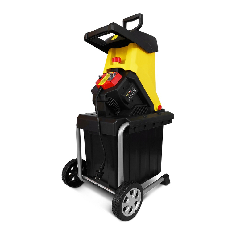
2500 WATT ELECTRIC
SILENT SHREDDER
WITH COLLECTOR
Model No: THSSWB -- Product No: 193818002
ASSEMBLY REQUIRED
SAVE THESE INSTRUCTIONS
SPARES & SUPPORT: 01793 333212
IMPORTANT
Please read & understand this manual, paying attention to the safety instructions, before use.
The manufacturer reserves the right to change the product specification and livery according to
continued product improvements.
All images used are for illustration purposes only.
INSTRUCTION MANUAL

2

CONTENTS
SPECIFICATIONS
IMPORTANT INFORMATION
GENERAL SAFETY INSTRUCTIONS
THE MACHINE
ASSEMBLY
OPERATION
CLEANING
MAINTENANCE
STORAGE & TRANSPORT
TROUBLE SHOOTING
NOTES
PARTS DIAGRAM & LIST
WARRANTY
EC DECLARATION OF CONFORMITY
ASSEMBLY IS REQUIRED
This product requires assembly before use. See the “Assembly” section for instructions.
Please check that all parts required for the assembly of this spreader are included. If for any
reason you believe a part for the assembly is missing or damaged, please contact us.
If you require any assistance with regards to the contents or operation of
your machine, please contact us:
TEL: 01793 333212
(MON –FRI 8.00AM TO 5.30PM EXCL. BANK HOLIDAYS)

SPECIFICATIONS
The manufacturer reserves the right to change the product specification and livery according to
continued product improvements.
Model Number
THSSWB
Product Number
193818002
Motor
AC-Motor 230V~50Hz
Motor rating P1 S6-40%
2,500W
Motor rating P1 S1
2,000W
Rotational speed cutting roller
40 min–1
Power Switch
Overload protection; cutting and reverse
function, zero- voltage initiator
Max. branch diameter (only for freshly cut wood)
Max. 40mm
Safety class
I
Protection class
IP X4
Measured sound power level
89.33dB(A) K=2.39dB(A)
Guaranteed LWA
95.0dB(A)
*The diameter of the branch is not the only factor that determines how easy it will be to shred. A
small branch can be difficult to shred when it has knots or is a particularly hard wood.
IMPORTANT INFORMATION
INTENDED USE
The device is intended for chopping up fibrous or woody organic material from household and
garden. It may not be filled with stones, glass, metal, bones, plastics or material scraps.
This product is not intended for commercial use. Generally acknowledged accident prevention
regulations and enclosed safety instructions must be observed.
Only perform work described in these instructions for use. Any other use is incorrect. The
manufacturer will not assume responsibility for damage resulting from such use.
ELECTRICAL REQUIREMENTS
Connect the main leads to a standard 230V+10% (50Hz+1Hz) electrical supply which has protection
devices for under-voltage, over-voltage, over-current as well as a residual current device (RCD) with
maximum residual current rated at 0.03A.
EXTENSIONS LEADS
Improper use of extension leads may cause inefficient operation of the log splitter which can result
in overheating. Be sure the extension lead is no longer than 10m and its cross-section is no less than
2.5mm² to allow sufficient current flow to the motor. Avoid use of loose or inadequately insulated
connections. Connections must be made with a protected material suitable for outdoor use.
WORKING CONDITIONS
This log splitter is a domestic use model. It is designed for operating under ambient temperatures
between +5°C and 40°C and for installation at altitudes no more than 1000m above M.S.L. The
surrounding humidity should be less than 50% at 40°C. It can be stored or transported under
ambient temperatures between -25°C and 55°C.
INSPECT YOUR BRANCH
Make sure there are no nails or foreign objects in branches to be shred.

GENERAL SAFETY INSTRUCTIONS
It is important that you read and understand the owner’s manual and labels affixed to the
machine. Learn its application and limitations as well as the specific potential hazards. Retain
these instructions for future reference. The operator is responsible for following the warnings &
instructions in this manual and on the product.
Read & understand operator’s manual
carefully before using the machine.
Failure to follow instructions could result
in death or serious injury.
Risk of Slicing.
Keep hands out of the way of all
moving parts.
Wear gloves to protect your hands
DO NOT REACH INTO THE
HOPPER
Whenever the machine is in use, safety
glasses must be worn to safeguard
against flying objects.
Hearing protection must also be used to
protect the operators hearing.
If the operator is working in an area
where there is a risk of falling objects, a
safety helmet must also be worn.
Unplug when not in use, before
making adjustments, changing
parts, cleaning, or working on the
log splitter. Consult the technical
manual before servicing.
Double Insulated Protection
DANGER
Foreign bodies may be thrown
from the machine
Check your machine before turning it on.
Keep guards in place and in working
order. Frequently check to see that tools
are removed from the machine area
before turning it on. Replace damaged,
missing or failed parts before using it.
10m
Keep all bystanders & animals at
least 10 metres away from the
machine during operation.
If approached, stop the machine
immediately.
Safety alert symbol. Used to alert you to potential personal injury hazards. Obey all safety messages that
follow this symbol to avoid possible injury.
DANGER
Indicates an imminently hazardous situation which, if not avoided, will result in serious injury.
WARNING
Indicates a potentially hazardous situation which, if not avoided, could result in serious injury
CAUTION
Indicates a potentially hazardous situation which, if not avoided, may result in minor or moderate injury.
CAUTION
Used without the safety alert symbol indicates a potentially hazardous situation which, if not avoided,
may result in property damage.

STAY ALERT
Do not operate the machine while under the influence of drugs, alcohol, or any medication that
could affect your ability to use it properly. Do not use this machine when you are tired or distracted
from the job at hand. Be aware of what you are doing at all times. Use common sense.
AVOID DANGEROUS CONDITIONS
Make sure there is adequate surrounding workspace. Cluttered areas invite injuries.
Keep your work area clean with sufficient light. Keep the area around the machine clear of
obstructions, grease, oil, rubbish and other debris which could cause persons to fall onto moving
parts.
Keep in mind, the operator is responsible for accidents or hazards occurring to people or their
property.
KEEP BYSTANDERS AND CHILDREN AWAY
Keep unauthorised persons a minimum distance of 10 metres away from the machine. If
approached, stop the machine immediately.
Do not allow children to operate, handle, climb on or in the machine.
INSPECT YOUR MACHINE
Check all bolts, nuts, and screws for tightness before each use, especially those securing guards and
drive mechanisms. Vibration during use, may cause these to loosen.
Form a habit of checking to see that all other tools/equipment are removed from the working area
before turning it on.
Replace damaged, missing or failed parts before using it. Warning labels carry important
information. Replace any missing or damaged warning labels.
DRESS PROPERLY
Do not wear loose clothing, gloves, scarfs, neckties or jewelry (rings, wrist watches), which can be
caught in moving parts. Protective electrically non-conductive gloves and non-skid heavy duty
footwear are highly recommended when working. Wear a face or dust mask if the operation is dusty.
Always wear safety glasses/goggles and/or face shields. Everyday eyeglasses have only impact
resistant lenses; they are not safety glasses/goggles. Wear protective hair covering to contain long
hair, preventing it from getting caught in machinery.
AVOID ELECTRICAL SHOCK
Check the electrical cord for signs of damage or ageing. If the cord becomes damaged in use, turn
the machine off immediately. DO NOT TOUCH THE CORD BEFORE DISCONNECTING THE SUPPLY. Do
not use the machine if the cord is damaged and have it replaced by an approved repairer.
Check that the electrical circuit is adequately protected and that it corresponds with the power,
voltage and frequency of the motor. Check that there is a ground connection, and a regulation
differential switch, further up the circuit. Ground the machine. Prevent body contact with grounded
surfaces: pipes, radiators, ranges, and refrigerator enclosures.
Never open the pushbutton box on the motor. Should this be necessary, contact a qualified
electrician. Make sure your fingers do not touch the plug’s metal prongs when plugging or
unplugging the machine.
EXTENSION CABLE
Use only IEC60245 (H07RN-F) extension cable for outdoor use with splash-proofed connector. Its
cross- section must be at least 1.5 mm2 for cable lengths up to 25 m, and 2.5 mm2 for cable lengths
over 25 m. Voltage drop may occur when using a long thin cable, this will reduce the power of the
machine. When using the extension cable, make sure that it does not interfere with the operation of
the machine and is not squeezed or bent, and the plug does not get wet. When using a cable reel,
wind the cable completely off the reel. Check the extension cable regularly for damage to the
insulation. Replace it if damaged.

DO NOT OVERREACH
Use the machine on a flat, level surface.
Keep proper footing and balance at all times when using the machine. Never stand on the machine.
Serious injury could occur if the machine is tipped or if the moving parts are unintentionally
contacted. Do not store anything above or near the machine, where anyone might stand on the
machine to reach them.
AVOID INJURY FROM UNEXPECTED ACCIDENT
Keep hands & feet out of the way of all moving parts. Do not place any part of your body or any tool
e.g. in the machine during operation.
DO NOT FORCE TOOL
Always work within the rated capacity. Do not use the machine for a purpose for which it was not
intended.
NEVER LEAVE MACHINE RUNNING UNATTENDED
Do not leave the machine unattended until it has come to a complete stop.
MAINTAIN YOUR MACHINE WITH CARE
Clean the machine immediately after use. Keep the machine clean to ensure it operates to its full &
safest performance. When maintaining this machine, only the manufacturer’s original replacement
parts should be used. The use of non-original manufacturer parts may invalidate your warranty.
PROTECT THE ENVIRONMENT
Take left over materials to an authorised collection point or follow the stipulations in the country
where the machine is used. Do not discharge into drains, soil or water.
STORE IDLE EQUIPMENT
When not in use, the machine should be stored in a dry location. Keep the machine away from
children and others not qualified to use it.
This symbol on the product or on its packaging indicates that this product may not be treated as
household waste. Instead it shall be handed over to the applicable collection point for the recycling
of electrical and electronic equipment.
For more detailed information about recycling of this product, please contact your local council
office, your household waste disposal service or shop where you purchased the product.

THE MACHINE


1
Filling Hopper
2
Power Switch
3
Handle
4
Electric 3-Pin Plug
5
Lock Lever
6
Control Panel
7
Upper Enclosure
8
Collection Box
9
Base Frame
10
Adjusting Knob
11
Fixing Knob
12
Blade Cover
13
Feeding Hopper
14
Screw
15
Counter Blade
16
Cutting Roller

ASSEMBLY
CAUTION
Always be sure that the machine is switched
off and unplugged before carrying out any
work on the tool.
Tools Required:
Cross Head Screwdriver
12mm Spanner
13mm Spanner
1. Place the upper enclosure upside down
on a flat surface. Then align the base
frame on to it. Make sure the base frame
is the right way around (Fig. 2).
2. Fasten the base frame to the upper
enclosure with the 6 screws. Make sure all
parts are perfectly stable and tightened
sufficiently (Fig 3).
3. Attach the feet using the 2 screws. Make
sure they are fastened tightly (Fig 4).
4. Attach the wheels (Fig 5):
-Put the wheel bolt through the spindle
sleeve.
-Place the wheel bolt and spindle sleeve
through the wheel.
-Place a washer on the wheel bolt before
inserting the bolt through the base leg.
Secure it with a nut. Make sure the nut is
tight, but the wheel still rotates.
-Repeat on the other side.
5. Insert the collection box and raise the lock
lever (Fig 6).
FUNCTIONS
WARNING
Before plugging the machine in, always make
sure that the machine is switched off.
Plugging the machine in with the switch on,
may cause an unexpected start resulting in
serious personal injury.
POWER SWITCH (Fig. 7)
CAUTION
Do not use the machine if the switch does
not turn it on and off. Defective switches
must be replaced by one of our authorised
service dealers.
To turn on the machine, push the (I)
Green on button.
To turn off the machine, push the (O) Red
off button.
AUTOMATIC SWITCH OFF
The machine switches off automatically when
a power failure occurs. To restart, push the
Green button again.
OVERLOAD PROTECTION
The motor is equipped with overload
protection. When overloaded, the machine
will run the following procedure:
The blade will run in reverse for 2 or 3
seconds to try to push the shredded
material back out.
The blade runs forward again.
If the material is still clogged after three
attempts to unblock itself, the machine
will stop.
Follow the below steps:
Turn off the machine.
Wait until the blades stop completely.
Remove the clogged material.
Turn the shredder on again after about 5
minutes, and feed material that is easier
to shred.
If you cannot turn on the machine after this
waiting time, refer to “Trouble Shooting”.
FORWARD / REVERSE SWITCH
CAUTION
Switch off the shredder before changing the
forward / reverse switch.
POSITION
The blades rotate in the forward direction.
POSITION
The blades rotate in the reverse direction to
release jammed material.
When you change the direction into
(reverse), hold the green power switch to
rotate the blades. The shredder automatically
stops when you release the power switch.
NOTE:
Several repetitions of reverse and forward
operations may be required to shred a large
object.

CAUTION
Always use a hook or a stick to remove
jammed objects to prevent accidents.
Always wait until the shredder stops
completely before restarting.
COLLECTION BOX
CAUTION
Switch off and unplug the machine before
attaching or removing the Collection Box.
Check the functionality of the interlock
feature every two hours for safe operation.
Never attempt to override the interlock
feature.
LOCK LEVER
Upper Position - The collection box is locked.
Lower Position - The collection box is
unlocked.
The machine cannot be switched on if the lock
lever is in the unlock position. The machine
automatically stops if the collection box is
unlocked during operation.
BLADE COVER
CAUTION
Make sure that the machine is switched off
and unplugged before opening the blade
cover.
Wear protective gloves before opening the
blade cover.
The cutter does not stop immediately after
switch off. Wait until all the parts stop.
If the material clogs badly in the upper
enclosure, remove it by opening the blade
cover.
OPERATION
SAFETY
Before starting the machine, make certain
the feeding chamber is empty.
Keep your face and body away from the
feed intake opening.
Do not allow hands, or any other part of
the body or clothing inside the feeding
chamber, discharge chute, or any moving
part.
If the cutting mechanism strikes any
foreign objects or if the machine should
start making any unusual noise or
vibration, immediately shut off the power
source and allow the machine to stop.
Disconnect the power source and inspect
for damage or faults.
Before operation, adjust the Adjusting
Knob to release any foreign objects which
may interfere with the Cutting Roller and
Counter Blade.
Switch on the tool, then adjust the
Adjusting Knob, you should hear the
Cutting Roller touching the Counter Blade.
The shredder should produce small metal
filings. Tighten the Fixing Knob, make sure
the Counter Blade is tight.
SET UP THE MACHINE:
On a flat, level surface. Do not place the
machine on graveled ground.
Work at a safe distance (at least 2 metres)
away from walls or other objects.
BEFORE STARTING, MAKE SURE THAT:
The connection cables are not damaged. If
there are cuts or tears, stop operation
and replace it immediately.
There is no damage on the machine, and
all screws are tight.
The machine is assembled completely and
correctly.
Check the mains connection:
Make sure that the mains voltage
matches the rated voltage on the
nameplate and the machine is properly
grounded.
Use only extension cords with sufficient
core cross-section.
The shredder can process the following types
of material:
All types of branches up to the machine's
maximum diameter capacity of 40mm,
depending on type and condition of the
wood.
Dry garden refuse such as plants, which
should be dried before shredding and fed
alternately with branches to avoid
blocking the shredder.

The shredder can NOT process the following
types of material:
Glass, metal, plastic, stone, ceramics,
thicker branches, hard wood, thick wood
plates, cloth, plastic bags, roots with soil.
Refuse which is in an almost liquid state,
e.g. kitchen waste.
OPERATION: (Fig. 8)
Feed the material into the filling hopper
from the right side.
In case of branches, twigs and wood,
shred them just after they are cut. They
may become very hard as they become
dry.
Remove any side shoots from branches, if
they are not easy to feed.
Turn off the motor & disconnect the
machine from the power supply, before
cleaning the ejection opening.
Do not let the shredded material
accumulate in the ejection opening.
Shredded material may block the ejection
opening. Empty the collection box
regularly.
Do not shred material which is more than
the maximum branch diameter of 40mm.
The maximum branch diameter may vary
depending on the freshness and condition
of the wood.
Shredding wet garden waste may clog the
shredder. To reduce the chance of the
machine clogging, alternate waste with
wood.
Soft material or wet branches may be torn
instead of cut. A worn counter blade may
also cause this problem.
ADJUSTING THE BLADE CLEARANCE (Fig. 9)
For an effective operation, adjust the
clearance between the counter blade &
cutting roller.
SETTING THE CLEARANCE:
Switch on the device.
Turn the fixing knob counterclockwise to
release the adjusting knob.
Turn the adjusting knob clockwise slowly
to place the counter blade closer to the
cutting roller. Turn it until fine aluminum
chips are falling from the ejection
opening.
Turn the fixing knob clockwise to lock the
adjusting knob.
REVERSE SWITCH
The shredder is fitted with a reverse
switch to enable the removal of jammed
material. If material becomes jammed
stop the machine by pressing the Red (O)
off button.
When the machine has come to a
complete stop, change the direction of
rotation by pressing the reverse arrow on
the reverse switch and pressing the Green
(I) on button (Note: the machine will not
stay Green (I) on while in reverse, the
button must be held down).
When the blockage has cleared, stop the
machine and return the reverse switch to
its original position. Do not continue to
run the machine in reverse mode as this
could cause injury to the operator or
damage to the machine.

MAINTENANCE
CAUTION
Always be sure that the machine is switched off and unplugged before inspecting or performing
maintenance.
Wear protective gloves before performing inspection or maintenance.
The cutter does not stop immediately after switch off. Wait until all the parts stop before
performing any maintenance work.
Make sure that all the tools are removed after
maintenance work.
Never use petrol, benzene, thinner, alcohol or similar.
Discoloration, deformation or cracks may result.
To clean the machine, use only moist cloth and soft brush.
Do not hose or clean the machine with high pressured water.
After each operation, perform the following maintenance:
Check whether all the locking screws are tight (tighten if necessary).
Lubricate metal parts to protect them against corrosion.
Keep the vents clean and free from dust.
The cutting roller and counter blade will wear out over time. Ask your nearest authorised service
dealer for replacement when it is necessary.
EMPTYING THE COLLECTOR
WARNING
Press the Red (O) off button and separate the device from the main power supply before removing
or inserting the collector.
Note: The Locking Lever (5) has the function of a safety switch and must be in its top position while
operating the product.
If the Locking Lever is correctly located, but the machine is not operating, the contacts of the locking
lever and the base frame must be cleaned, if required.
Move Locking Lever to bottom position.
Pull the collection container completely out of the frame.
Empty the container.
Slide the collection container onto the frame as far as it will go.
Move Locking Lever to the top position.
Note: Stones, nails or similar objects can cause major damage to the chipper. (CHECK CAREFULLY)
If the chipper begins to vibrate strongly, the blades are damaged or worn out. Replace the blades if
necessary (see later pages in this manual for details).

CLEANING
DANGER
Before all cleaning and maintenance work, switch the device off and disconnect the mains plug
from the electrical source. Wait until all moving parts have come to a complete stop and the
device is cooled off.
CLEANING THE DEVICE
Careful handling and regular cleaning ensure that the device will remain functional & powerful
for a long time.
Brush off coarse dirt.
Wipe down the device with a slightly damp cloth.
Never spray the device with water or subject it to water.
To clean, never use cleansers or solvents. This can cause irreparable damage to the device. The
plastic parts can be eaten away by the chemicals.
STORAGE & TRANSPORT
STORAGE
WARNING
Make sure that unauthorised persons do not have access to the device!
Allow the device to cool completely, before storing.
Store the machine in a dry place.
Store away from direct sunlight.
Do not store anything above or near the machine, where anyone might stand on the machine to
reach them.
Keep the machine away from children and others not qualified to use it.
TRANSPORT
Secure the device against slipping.
When shipping, use the original packaging if possible.

TROUBLE SHOOTING
DANGER
Improper repairs can cause your device to stop functioning safely. You therefore endanger
yourself, bystanders and your environment. You also risk invalidating your manufacturer’s
warranty.
PROBLEM
PROBABLE CAUSE
REMEDY SUGGESTED
Motor does not
start
No Mains Voltage?
Check cable, plug, socket and
fuse.
Cable Faulty?
Contact your local Approved
Service Dealer or Electrical
Specialist if out of Warranty.
Motor Protection Activated?
Allow the machine to cool down
and press Green (I) on button.
Locking Lever is not locked?
Ensure Locking Lever on
collector is in locked position.
Motor sounds but
does not start
Cutting roller is blocked
Turn off the device.
Switch the forward/reverse
switch into the reverse direction.
Switch on the machine until the
jam has been cleared. Switch the
machine off again. Change the
direction to forward rotation.
Capacitor fault
Bring the machine to one of our
service dealers for repair.
The shredding
material is
not drawn into
the shredder
Reverse rotation.
Turn off the machine and change
the direction of rotation, using
the selector switch.
Shredding material
jammed in hopper
Switch off the machine. Switch
the forward/reverse switch to
the reverse direction. Switch on
the machine to release the
material, remove any foreign
matter. Switch the machine off
again. Change the direction to
forward rotation.
Shredding material too soft or wet
Push down with a branch
Cutting roller worn
Adjust the fixed counter blade as
described under "Adjusting the
blade clearance”. If the cutting
roller is severely worn, replace it.
Shredding material
is not cut cleanly
Fixed counter blade is not adequately
adjusted
Adjust the counter blade.
Device starts but is
blocked by slight
load & is switched
off by the
protective motor
switch.
Extension cable is too long or
cross-section is too thin.
Socket is too far from mains supply or
cross-section of mains cable is too thin.
Check the extension cable is at
least 1.5mm², maximum 25m
long. If using longer cable,
minimum cross-section is 2.5mm

NOTES
_____________________________________________
_____________________________________________
_____________________________________________
_____________________________________________
_____________________________________________
_____________________________________________
_____________________________________________
_____________________________________________
_____________________________________________
_____________________________________________
_____________________________________________
_____________________________________________
_____________________________________________
_____________________________________________
_____________________________________________
_____________________________________________
_____________________________________________
_____________________________________________
_____________________________________________
_____________________________________________
_____________________________________________
_____________________________________________
_____________________________________________
_____________________________________________
_____________________________________________
_____________________________________________

PARTS DIAGRAM –THSSWB (193818002)
NOTE: Parts Lists are supplied for information
purposes only, not all parts are stocked
individually & we recommend you contact our
Spares Team on 01793 333212 for expert advice.

PARTS LIST –THSSWB (193818002)
Item No
Part No
Description
QTY
1
TH203-1
Screw
7
2
TH203-2
Switch Assembly
1
3
TH203-3
Switch Housing
1
4
TH203-4
Hopper Top
1
5
TH203-5
Feeder
1
6
TH203-6GM
Upper Housing
1
7
TH203-7
Self-Tapping Screw
18
8
TH203-8
Power Cable
1
9
TH203-9
Screw
1
10
TH203-10
Lock Washer
1
11
TH203-11
Heat Shrinkable Tube
1
12
TH203-12
Capacitor
1
13
TH203-13
Switch
1
14
TH203-14
Micro-switch
1
15
TH203-15
Motor
1
16
TH203-16
Adjuster Knob
1
17
TH203-17
Lock Knob
1
18
TH203-18
Nut holder
1
19
TH203-19
Nut Housing
1
20
TH203-20
Inlet Baffle
1
21
TH203-21
Type A Flat Key
1
22
TH203-22
Blade
1
23
TH203-23
End Cover
1
24
TH203-24
Screw
2
25
TH203-25
Nylon Cable Tie
6
26
TH203-26
Switch Board
1
27
TH203-27
Lower Housing
1
28
TH203-28
Screw
2
29
TH203-29
Screw
2
30
TH203-30
Base Assembly
1
30-1
TH203-30-1
Base Plate
1
30-2
TH203-30-2
Cable Clamp
2
30-3
TH203-30-3
Self-Tapping Screw
4
30-4
TH203-30-4
Support Base
1
30-5
TH203-30-5
Clamp
2
30-6
TH203-30-6
Self-Tapping Screw
4
31
TH203-31
Wheel Assembly
2
31-1
TH203-31-1
Wheel Cap
1
31-2
TH203-31-2
Wheel Bolt
1
31-3
TH203-31-3
Spindle Cover
1
31-4
TH203-31-4
Wheel
4
31-5
TH203-31-5
Washer
2
31-6
TH203-31-6
Nut
1
32
TH203-32
Bracket Assembly
2
32-1
TH203-32-1
Screw
1
32-2
TH203-32-2
Bracket Assembly
1
32-3
TH203-32-3
Nut
1
33
TH203-33
Collector Box Assembly
1
33-1
TH-203-33-1
Push Button
1
33-2
TH-203-33-2
Button Rod
1
33-3
TH-203-33-3
Self-Tapping Screw
1
33-4
TH-203-33-4
Screw
4
33-5
TH-203-33-5
Rod Housing
1
33-6
TH-203-33-6
Collector Box
1
34
TH203-34
Allen Key
1

GJ HANDY & CO LTD USER WARRANTY POLICY
Users Statement of Warranty
Each new machine is warranted against defective material or assembly of material under normal
usage. The warranty applies to the original purchaser and covers faulty parts and the labour involved
in replacing and repairing those parts, which are of original manufacture.
Period of Warranty
All Webb & Webb Pro machines plus Sanli engines.
a) 2 years from the original date of sale to the first domestic user.
b) 90 days from the original date of sale to the professional/commercial user.
c) 90 days from the original date of sale when used for hire.
d) A reduced warranty period of 90 days applies to those items which are subject to normal wear
and tear (e.g. but not limited to wheels, tyres, cutter bars, cylinders, blades, belts, cables, grass
bags, spark plugs).
e) Engines as per the manufacturer’s warranty statement which will be supplied with the machine.
f) 90 days from the original date of purchase for Replacement Spare Parts (unless normal wear &
tear component, which are covered for 30 days).
g) All machines’ must be serviced within the first 12 months from the original date of purchase to
comply with the warranty, failure to do so will invalidate the 2nd year of the warranty.
All Handy, Mowerland and Q-Garden products.
a) 1 year from the original date of sale to the first domestic user.
b) 90 days from the original date of sale to the professional/commercial user.
c) 90 days from the original date of sale when used for hire.
d) A reduced warranty period of 90 days applies to those items which are subject to normal wear
and tear (e.g. but not limited to wheels, tyres, cutter bars, cylinders, bottom blades, belts,
cables, collection bags, spark plugs).
e) Engines as per the manufacturer’s warranty statement which will be supplied with the machine.
f) 90 days from the original date of purchase for Replacement Spare Parts (unless normal wear &
tear component, which are covered for 30 days).
All warranty repairs must be undertaken by an authorised service dealer. These dealers have been
accredited by GJ Handy & Co Ltd and agree to only use genuine parts and follow our repair
procedures.
Version 4 10-16
Other manuals for THSSWB
1
Table of contents
Other The Handy Paper Shredder manuals

The Handy
The Handy THHSWB Installation and maintenance instructions
The Handy
The Handy THIS User manual

The Handy
The Handy THIS Installation and maintenance instructions
The Handy
The Handy THISWB User manual

The Handy
The Handy THSS User manual
The Handy
The Handy THSSWB User manual

The Handy
The Handy THIS User manual

The Handy
The Handy THPDS65 User manual
Popular Paper Shredder manuals by other brands

SEM
SEM 0205 Operation and maintenance manual
Krug & Priester
Krug & Priester IDEAL 2604 operating instructions

PRO Intellect Technology
PRO Intellect Technology PRO KGB C-11CC user manual

Fellowes
Fellowes PS-14Cs instruction manual

HSM
HSM 450 instruction manual
Fellowes
Fellowes POWERSHRED 2127M user manual

