The Handy THISWB User manual

THISWB - 193895001
07/03/2016
INSTRUCTION
MANUAL
2500 WATT ELECTRIC IMPACT SHREDDER
WITH COLLECTOR & HOPPER
SPARES & SUPPORT: 01793 333212
Please read & understand this manual, payingparticular attention to the safety instructions, before
use.
The manufacturer reserves the right to change the product specification and livery according to
continued product improvements.


CONTENTS
SPECIFICATIONS
IMPORTANT INFORMATION
GENERAL SAFETY INSTRUCTIONS
THE MACHINE
ASSEMBLY
OPERATION
CLEANING
MAINTENANCE
STORAGE & TRANSPORT
TROUBLE SHOOTING
NOTES
PARTS DIAGRAM & LIST
WARRANTY
EC DECLARATION OF CONFORMITY
Assembly Is Required
This product requires assembly before use. See the “Assembly” section for instructions.
Please check that all parts required for the assembly of this spreader are included. If for any
reason you believe a part for the assembly is missing or damaged, please contact us.
If you require any assistance with regards to the contents or operation of
your machine, please contact us:
TEL: 01793 333212
(MON –FRI 8.00AM TO 5.30PM EXCL. BANK HOLIDAYS)

SPECIFICATIONS
The manufacturer reserves the right to change the product specification and livery according to
continued product improvements.
Model Number
THISWB
Product Number
193895001
Voltage
230-240V~, 50Hz
Rated Power (Watt)
2500
Idle Speed (rpm)
4500
Maximum Branch Diameter (mm)
45
Collector Capacity (Litre)
40
Cable (m)
3
Degree of Protection
IP24
Protection Class
II
Overall Size (mm)
(L) 460
(W) 360 front - 455 rear with wheels
(H) 1050 –1230 with Hopper
Weight (kg)
G.W 14.5 - N.W 13.8
* The diameter of the branch is not the only factor that determines how easy it will be to shred. A
small branch can be difficult to shred when it has knots or is a particularly hard wood.
IMPORTANT INFORMATION
INTENDED USE
The device is intended for chopping up fibrous or woody organic material from household and
garden. It may not be filled with stones, glass, metal, bones, plastics or material scraps.
This product is not intended for commercial use. Generally acknowledged accident prevention
regulations and enclosed safety instructions must be observed.
Only perform work described in these instructions for use. Any other use is incorrect. The
manufacturer will not assume responsibility for damage resulting from such use.
ELECTRICAL REQUIREMENTS
Connect the main leads to a standard 230V+10% (50Hz+1Hz) electrical supply which has protection
devices for under-voltage, over-voltage, over-current as well as a residual current device (RCD) with
maximum residual current rated at 0.03A.
EXTENSIONS LEADS
Improper use of extension leads may cause inefficient operation of the log splitter which can result
in overheating. Be sure the extension lead is no longer than 10m and its cross-section is no less than
2.5mm² to allow sufficient current flow to the motor. Avoid use of loose or inadequately insulated
connections. Connections must be made with a protected material suitable for outdoor use.
WORKING CONDITIONS
This log splitter is a domestic use model. It is designed for operating under ambient temperatures
between +5°C and 40°C and for installation at altitudes no more than 1000m above M.S.L. The
surrounding humidity should be less than 50% at 40°C. It can be stored or transported under
ambient temperatures between -25°C and 55°C.
INSPECT YOUR BRANCH
Make sure there are no nails or foreign objects in branches to be shred.
GENERAL SAFETY INSTRUCTIONS
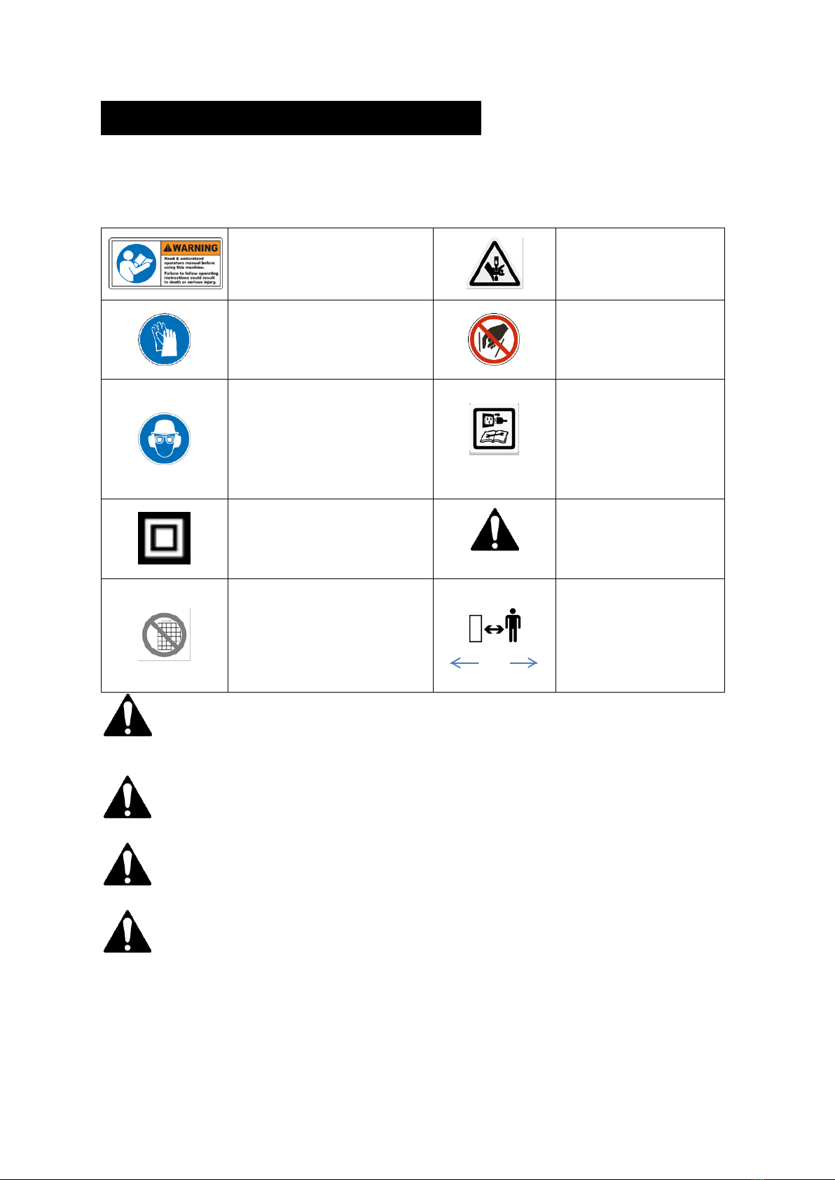
It is important that you read and understand the owner’s manual and labels affixed to the
machine. Learn its application and limitations as well as the specific potential hazards. Retain
these instructions for future reference. The operator is responsible for following the warnings &
instructions in this manual and on the product.
Read & understand operator’s manual
before using the machine. Failure to
follow instructions could result in death
or serious injury.
Risk of Slicing.
Keep hands out of the way of all
moving parts.
Wear gloves to protect your hands
DO NOT REACH INTO THE
HOPPER
Whenever the machine is in use, safety
glasses must be worn to safeguard
against flying objects.
Hearing protection must also be used to
protect the operators hearing.
If the operator is working in an area
where there is a risk of falling objects, a
safety helmet must also be worn.
Unplug when not in use, before
making adjustments, changing
parts, cleaning, or working on the
log splitter. Consult the technical
manual before servicing.
Double Insulated Protection
DANGER
Foreign bodies may be thrown
from the machine
Check your machine before turning it on.
Keep guards in place and in working
order. Frequently check to see that tools
are removed from the machine area
before turning it on. Replace damaged,
missing or failed parts before using it.
10m
Keep all bystanders & animals at
least 10 metres away from the
machine during operation.
If approached, stop the machine
immediately.
Safety alert symbol. Used to alert you to potential personal injury hazards. Obey all safety messages that
follow this symbol to avoid possible injury.
DANGER
Indicates an imminently hazardous situation which, if not avoided, will result in serious injury.
WARNING
Indicates a potentially hazardous situation which, if not avoided, could result in serious injury
CAUTION
Indicates a potentially hazardous situation which, if not avoided, may result in minor or moderate injury.
CAUTION
Used without the safety alert symbol indicates a potentially hazardous situation which, if not avoided,
may result in property damage.

STAY ALERT
Do not operate the machine while under the influence of drugs, alcohol, or any medication that
could affect your ability to use it properly. Do not use this machine when you are tired or distracted
from the job at hand. Be aware of what you are doing at all times. Use common sense.
AVOID DANGEROUS CONDITIONS
Make sure there is adequate surrounding workspace. Cluttered areas invite injuries.
Keep your work area clean with sufficient light. Keep the area around the machine clear of
obstructions, grease, oil, rubbish and other debris which could cause persons to fall onto moving
parts.
INSPECT YOUR MACHINE
Check all bolts, nuts, and screws for tightness before each use, especially those securing guards and
drive mechanisms. Vibration during use, may cause these to loosen.
Form a habit of checking to see that all other tools/equipment are removed from the working area
before turning it on.
Replace damaged, missing or failed parts before using it. Warning labels carry important
information. Replace any missing or damaged warning labels.
DRESS PROPERLY
Do not wear loose clothing, gloves, scarfs, neckties or jewelry (rings, wrist watches), which can be
caught in moving parts. Protective electrically non-conductive gloves and non-skid heavy duty
footwear are highly recommended when working. Wear a face or dust mask if the operation is dusty.
Always wear safety glasses/goggles and/or face shields. Everyday eyeglasses have only impact
resistant lenses; they are not safety glasses/goggles. Wear protective hair covering to contain long
hair, preventing it from getting caught in machinery.
AVOID ELECTRICAL SHOCK
Check that the electrical circuit is adequately protected and that it corresponds with the power,
voltage and frequency of the motor. Check that there is a ground connection, and a regulation
differential switch, further up the circuit. Ground the machine. Prevent body contact with grounded
surfaces: pipes, radiators, ranges, and refrigerator enclosures.
Never open the pushbutton box on the motor. Should this be necessary, contact a qualified
electrician. Make sure your fingers do not touch the plug’s metal prongs when plugging or
unplugging the machine.
KEEP BYSTANDERS AND CHILDREN AWAY
Keep unauthorised persons a minimum distance of 10 metres away from the machine. If
approached, stop the machine immediately. Do not allow children to handle, climb on or in the
machine.
DO NOT OVERREACH
Keep proper footing and balance at all times when using the machine. Never stand on the
machine. Serious injury could occur if the machine is tipped or if the moving parts are
unintentionally contacted. Do not store anything above or near the machine, where anyone might
stand on the machine to reach them.
AVOID INJURY FROM UNEXPECTED ACCIDENT
Keep hands & feet out of the way of all moving parts. Do not place any part of your body or any
tool e.g. in the machine during operation.
DO NOT FORCE TOOL
Always work within the rated capacity. Do not use the machine for a purpose for which it was not
intended.
NEVER LEAVE MACHINE RUNNING UNATTENDED
Do not leave the machine unattended until it has come to a complete stop.

MAINTAIN YOUR MACHINE WITH CARE
Clean the machine immediately after use. Keep the machine clean to ensure it operates to its full &
safest performance. When maintaining this machine, only the manufacturer’s original replacement
parts should be used. The use of non-original manufacturer parts may invalidate your warranty.
PROTECT THE ENVIRONMENT
Take left over materials to an authorised collection point or follow the stipulations in the country
where the machine is used. Do not discharge into drains, soil or water.
STORE IDLE EQUIPMENT
When not in use, the machine should be stored in a dry location. Keep the machine away from
children and others not qualified to use it.
This symbol on the product or on its packaging indicates that this product may not be treated as
household waste. Instead it shall be handed over to the applicable collection point for the recycling
of electrical and electronic equipment.
For more detailed information about recycling of this product, please contact your local council
office, your household waste disposal service or shop where you purchased the product.
THE MACHINE
SUPPLIED AS STANDARD
Instruction Manual, Shredder, Collector, Paddle Prod, Frame, Axle, Wheels, Wheel Trims, Fixing Kit
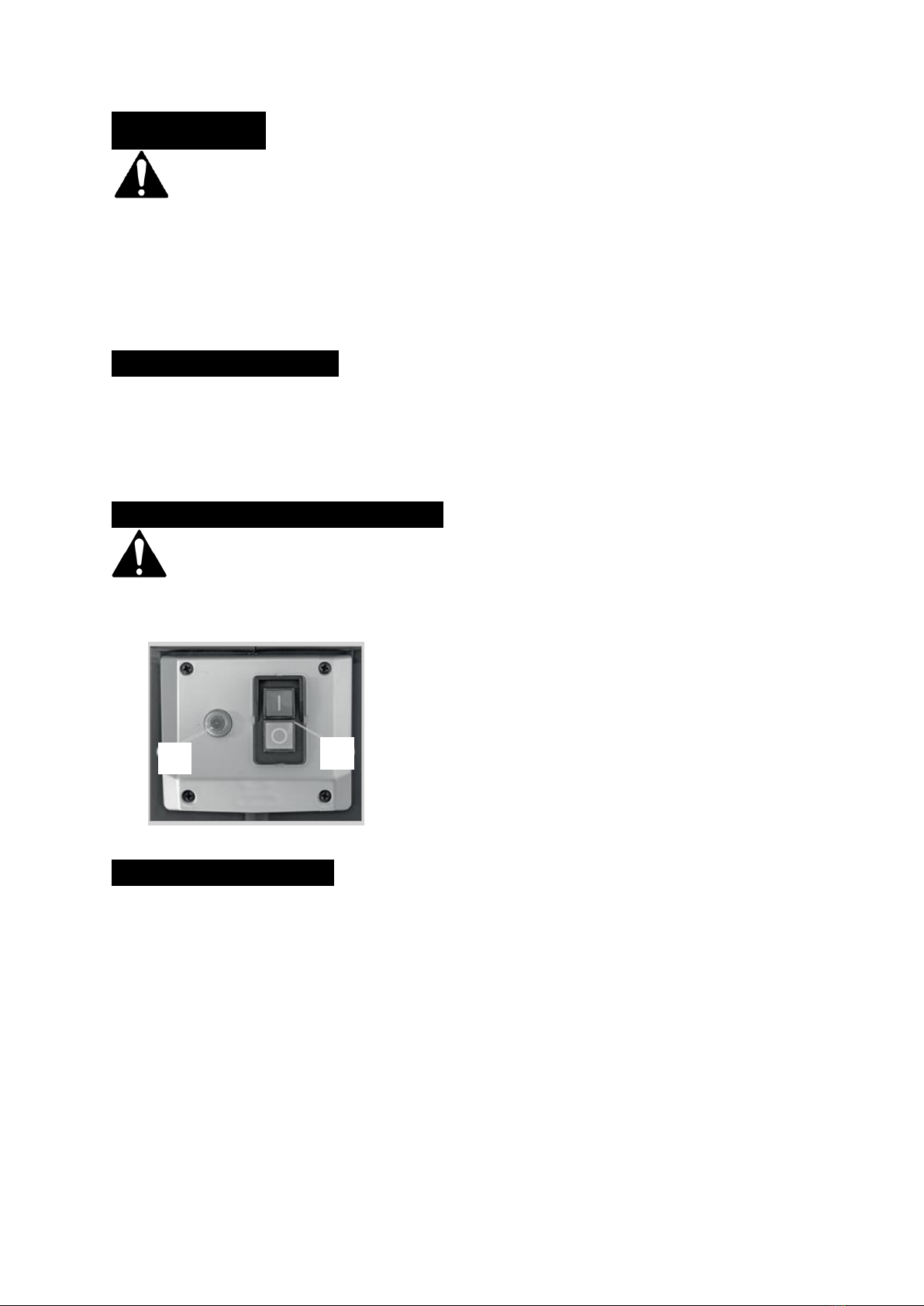
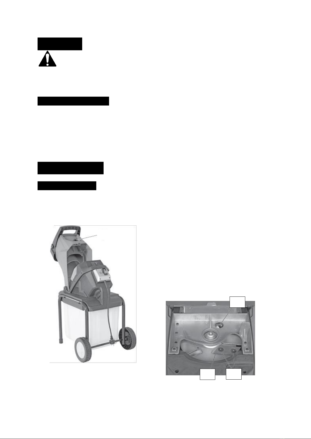
1. The Hopper
2. Reset Button
3. Transport Handle
4. Locking Screw
5. On-Off Switch
6. Mains Three Pin Plug
7. Collector Locking Lever
8. Collector
1
5
4
3
2
6
8
7

ASSEMBLY
–
Screw down the frame (9) to the device as illustrated with the screws (10).
–
Push the axle (11) into the frame.
–
Push the washer and socket (12) onto the axle.
–
Push the wheel onto the axle.
–
Tighten the wheel with the washer and nut (13).
–
Place the wheel cap on the wheel.
–
Repeat the procedure for the other wheel.
–
Push the collection tray (8) into the frame.
–
Change locking lever (7) to top position.
8
7
OPERATION
DANGER
The product must only be put into operation if no defects are found. It is crucial that any
defective parts are replaced before the product is used again.
Check the safety equipment and the safe condition of the product:
–
Check whether the hopper is empty.
–
Check all parts to make sure that they fit tightly.
–
Check whether there are any visible defects: broken parts, cracks, etc.
COLLECTOR LOCK LEVER
The machine is supplied with a safety function, which prevents it being operated if the collector lock
lever is in the unlock position. The machine will automatically stop, if the collection box is unlocked
during operation.
Upper position → The collection box is locked.
Lower position → The collection box is unlocked.
SWITCHING THE MACHINE ON & OFF
Before starting the product, make sure that there is no material in the hopper.
Before feeding material in, wait until the chipper has reached its working speed.
Switch on = Press Green [I] Button
Switch off = Press Red [0] Button
OVERLOAD PROTECTION
Note: If a blocked blade causes an overload, the circuit is automatically interrupted to protect the
motor.
–
Unplug the machine from the electrical source.
–
Remove blocked chippings. Note: Allow the motor to cool down for at least five minutes!
–
Press Reset Button (2).
–
Re-connect the power supply.
–
Start theproduct.
2
3

EMPTY THE COLLECTOR
WARNING
Press the Off Button [O] and separate the device from the main power supply before removing or
inserting the collector.
Note: The Locking Lever has the function of a safety switch and must be in its top position while
operating the product.
If the Locking Lever is correctly located, but the machine is not operating, this & the switch must be
cleaned, if required.
–
Move Locking Lever (7) to bottom position.
–
Pull the collection container (8) completely out of the
frame.
–
Empty the container (8).
–
Slide the collection container (8) onto the frame as far as
it will go.
–
Move Locking Lever (7) to top position, when
NOTES ABOUT CHIPPING
–
Organic garden waste can be chipped as biological fertiliser for the garden. Feed material which
breaks down naturally such as leaves, small branches, and grass in appropriate quantities into
the hopper (1) so that it does not get blocked.
–
Alternate chipping branches and garden waste, that has been stored for a few days & is
therefore withered and damp. This prevents blocking of the motor cylinder.
–
Do not put soft waste such as kitchen waste into the chipper; compost it instead.
–
Large branches with leaves must first be chipped completely before any other material is fed in.
–
If you cut heavy material or branches without interruption, this may block the chipper. Pull out
the material by hand a little, to counteract this problem (DO NOT REACH INTO THE HOPPER).
–
Stones, nails or similar objects can cause major damage to the chipper. (CHECK CAREFULLY)
–
If the chipper begins to vibrate strongly, the blades are damaged or worn out. Replace the
blades if necessary (see later pages in this manual for details).
ATTACH THE HOPPER
The detachable hopper can be fitted and removed from the top of the shredder to help the user
feed material into the shredder.
–
Place the hopper on top of the shredder.
–
Loosen the green side clasps on the hopper.
–
Ensure the metal link is positioned under
the hook of the shredder.
–
Pull the green side clasps of the hopper
upwards to lock into place.
–
To remove, follow the above steps in
reverse.
7
8
CLEANING
DANGER
Before all cleaning and maintenance work, switch the device off and disconnect the mains plug
from the electrical source. Wait until all moving parts have come to a complete stop and the
device is cooled off.
CLEANING THE DEVICE
–
Careful handling and regular cleaning ensure that the device will remain functional & powerful
for a long time.
–
Brush off coarse dirt.
–
Wipe down the device with a slightly damp cloth.
–
Never spray the device with water orsubject it to water.
–
To clean, never use cleansers or solvents. This can cause irreparable damage to the device. The
plastic parts can be eaten away by the chemicals.
MAINTENANCE
CHANGING BLADES
SAFETY GLOVES MUST BE WORN AT ALL TIMES.
–
Loosen the closure screw (4) and fold out
the hopper.
–
Insert a suitable object (Allen Key or
Screwdriver) as shown and hold it in the
hole (14).
–
Loosen the screws (15) with an Allen
Key.
–
Turn or replace the blade (16).
–
Install in the reverse order.
Note: Blades can also be sharpened.
However, this should be done by a
professional, both blades must maintain the
same weight in order to maintain a balanced
operation. An imbalance of the blades can
cause damage and injuries.
4
16
14
15

STORAGE & TRANSPORT
STORAGE
WARNING
Make sure that unauthorised persons do not have access to the device!
–
Allow the device to cool completely, before storing.
–
Store the machine in a dry place.
–
Store away from direct sunlight.
–
Do not store anything above or near the machine, where anyone might stand on the machine to
reach them.
–
Keep the machine away from children and others not qualified to use it.
TRANSPORT
–
Secure the device against slipping.
–
When shipping, use the original packaging if possible.
TROUBLE SHOOTING
DANGER
Improper repairs can cause your device to stop functioning safely. You therefore endanger
yourself, bystanders and your environment. You also risk invalidating your manufacturer’s
warranty.
PROBLEM
PROBABLE CAUSE
REMEDY SUGGESTED
Motor not running.
No Mains Voltage?
Check cable, plug, socket and fuse.
Cable Faulty?
Contact your local Approved Service
Dealer or Electrical Specialist if out of
Warranty.
Motor Protection Activated?
Remove all chipped debris & press
reset button
Safety Trigger not triggered?
Check the hopper motor housing
connection
Locking Lever is bottom
position?
Ensure Locking Lever on collector is
positioned in upper most position.
Material is not being
pulled into machine.
Material blockage?
Remove all chipped debris from blades.
(SAFETY GLOVES MUST BE WORN)
Are the blades
jammed/blocked?
Remove all chipped debris & press
reset button
Are the blades worn?
Replace the blades where necessary,
see blade removal instructions.

NOTES
_____________________________________________
_____________________________________________
_____________________________________________
_____________________________________________
_____________________________________________
_____________________________________________
_____________________________________________
_____________________________________________
_____________________________________________
_____________________________________________
_____________________________________________
_____________________________________________
_____________________________________________
_____________________________________________
_____________________________________________
_____________________________________________
_____________________________________________
_____________________________________________
_____________________________________________
_____________________________________________
_____________________________________________
_____________________________________________
_____________________________________________
_____________________________________________
_____________________________________________
_____________________________________________
_____________________________________________
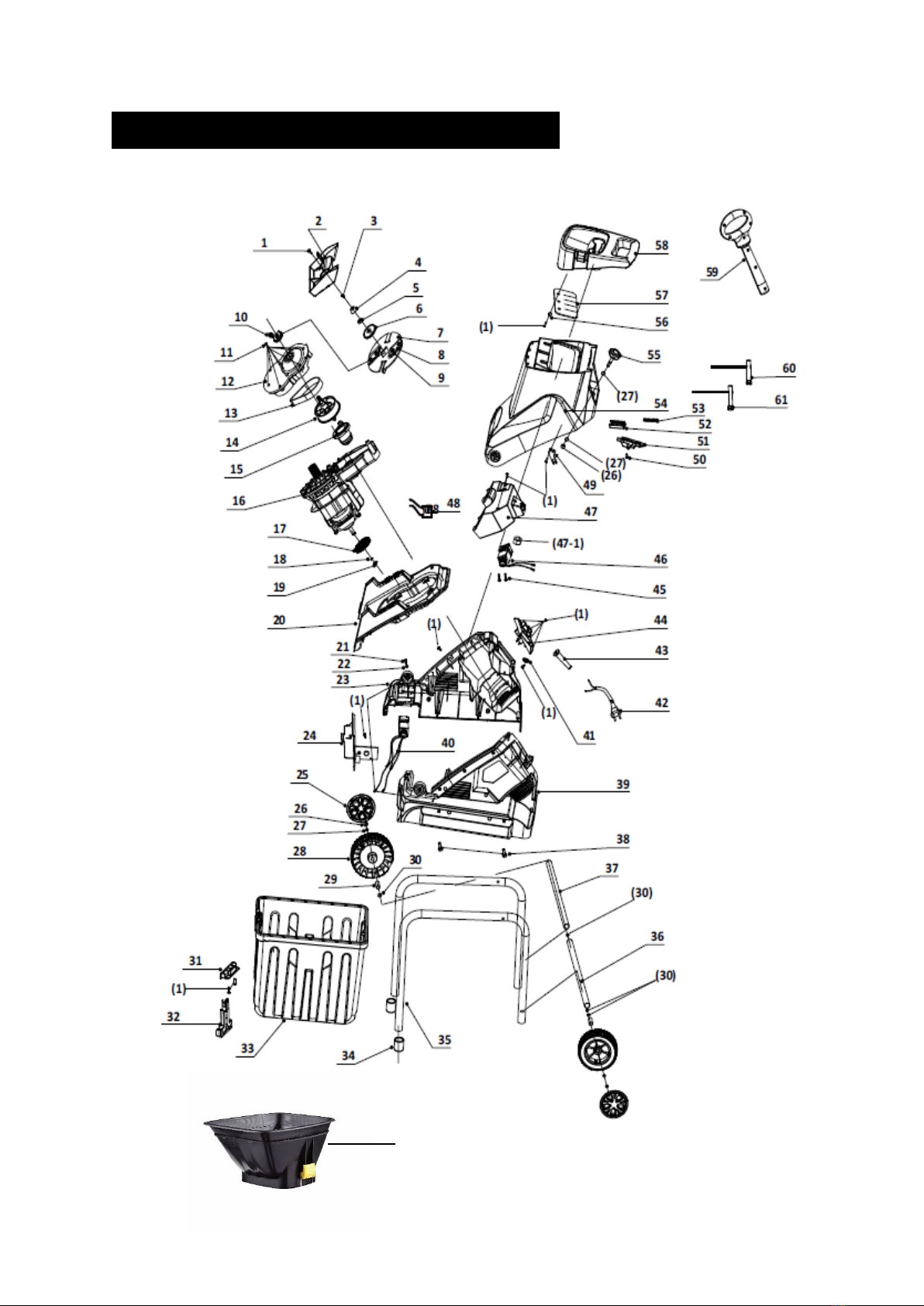
PARTS DIAGRAM –THISWB (193895001)
62
NOTE: Parts Lists are supplied for information
purposes only, not all parts are stocked
individually & we recommend you contact our
Spares Team on 01793 333212 for expert advice.

PARTS LIST –THISWB (193895001)
ITEM
HANDY PART NO.
DESCRIPTION
QTY
ITEM
HANDY PART
NO.
DESCRIPTION
QTY
1
TH104030161
S.T Screw 4.2 X 15B
47
29
TH103010098
Wheel Sleeve Φ14Xφ10X32
2
2
TH4010022
Blade Defend Plate
1
30
TH104010136
Flat Washer Ф10Xф20X1.5
4
3
TH104030408
Bolt M5X12
1
31
TH3010800086
Collector Key Entrance
1
4
TH103990484
Nut Cover
1
32
TH3010800087A
Collector Switch
1
5
TH104020048
Check Nut M12
1
33
TH301080367
Collector
1
6
TH103990450
Blade Block
1
34
TH301080369
Rubber Feet
2
7
TH103990449-1
Blade Plate Φ178.5X5
1
35
TH4050141
Supporting Leg Assembly
2
8
TH103040077B
Blade
2
36
TH4050143
Axle Sleeve Ф14*Ф12*308
1
9
TH104030246
Hex.Socket Bolt
M10X12
4
37
TH103050227
Axle 451*Ф10*M8
1
10
TH103990448
Drive Block
1
38
TH104030407
Hex.Socket Bolt M6X45
4
11
TH104030149
S.T Screw 4.8X19B
8
39
TH301080363
Left Housing
1
12
TH3010800069
Gearbox Top Cover
c/w Bearing Assembly
1
40
TH4080038
Pre Forced Switch
1
13
TH105990120
Belt 10PJ375
1
41
TH301990135
Cord Clamp
1
14
TH3010800072
Pulley
1
42
TH102070670
Three Pin Plug & Cable
1
15
TH3010800071
Pulley Tensioner
1
43
TH3010800063
Cable Sheath
1
16
TH4070184
Motor Assembly
1
44
TH4080041
Switch Assembly
1
TH2020121
S.T Screw 5X85B
2
TH102990141
Over-Load Protector
1
TH301080368
Motor Bracket
1
TH301080366
Switch Panel
1
TH102010386A
Motor Stator
1
TH102020203
Solenoid Switch
1
TH104030010
Male Tab F6.3*0.5
2
45
TH104030247
S.T Screw 4.2X35
2
TH103050142
Little Belt Wheel
1
46
TH4080039
Back Forced Switch
1
TH103050144
Bearing
1
47
TH301080361
Blade Panel Upper Cover
1
TH102010386B-1
Motor Rotor
1
47-1
TH104020072
Nut M8*14*11.7
1
TH103050100
Bearing
1
48
TH102030030
Capacitor
1
TH102060061
Brush Assembly
17*13*7
2
49
TH103990724
Key
1
TH103020119
Brush Bracket
2
50
TH104030126
S.T Screw 3*8 A
4
TH301080373-1
Motor Back
1
51
TH301080377
Top Block
1
17
TH301080375
Fan Ф95
1
52
TH301080376
Cover Plate
1
18
TH104050007
C-Ring Ф9
1
53
TH103060273
Spring Φ0.5*Φ4.8*40
1
19
TH3010800060
Fan Cover
1
54
TH301080360
Upper Housing
1
20
TH301080362
Blade Panel Base
1
55
TH301080123I-1
Knob
1
21
TH104030159
S.T Screw 4.2X10B
2
TH103990725-1
Knob Insert
1
22
TH104010135
Flat Washer
Ф4Xф11X1.5
2
56
TH104010024
Flat Washer Φ5*Φ14*1.5
3
23
TH301080364
Right Housing
1
57
TH301080356
Inlet Back Plate
1
TH103990748
Housing Insert M6*9.2
4
58
TH301080374
Inlet Panel Plate
1
24
TH301080365
Cable Cover
1
59
TH3010800030
Plunger
1
25
TH301080126G
Wheel Trim
2
60
TH4050083-1
Allen Key
1
26
TH104020020
Check Nut M8
3
61
TH103090050
Allen Key
1
27
TH104010047
Flat Washer
Ф8Xф20X1.5
4
62
TH3880065
Hopper
1
28
TH301080119
Wheel
2

GJ HANDY & CO LTD USER WARRANTY POLICY
1. Users Statement of Warranty
Each new machine is warranted against defective material or assembly of material under normal
usage. The warranty applies to the original purchaser and covers faulty parts and the labour involved
in replacing and repairing those parts, which are of original manufacture.
2. Period of Warranty
All Webb, Handy Pro (Brushcutter & Long Handle Hedgecutter only) products
2 years from the original date of sale to the first domestic user.
90 days from the original date of sale to the professional/commercial user.
90 days from the original date of sale when used for hire.
Engines as per the manufacturer’s warranty statement which will be supplied with the machine.
90 days from the original date of purchase for Replacement Spare Parts (unless normal wear & tear
component, which are covered for 30 days).
All machines’ must be serviced within the first 12 months from the original date of purchase to
comply with the warranty, failure to do so will invalidate the 2nd year of the warranty.
A reduced warranty period of 90 days applies to those items which are subject to normal wear and
tear (e.g. wheels, tyres, cutter bars, cylinders, bottom blades, belts, cables, grass bags, spark plugs).
All Handy, Handy Pro (All others), Mowerland and Q-Garden domestic products
1 year from the original date of sale to the first domestic user.
90 days from the original date of sale to the professional/commercial user.
90 days from the original date of sale when used for hire.
Engines as per the manufacturer’s warranty statement which will be supplied with the machine.
90 days from the original date of purchase for Replacement Spare Parts (unless normal wear & tear
component, which are covered for 30 days).
A reduced warranty period of 90 days applies to those items which are subject to normal wear and
tear (e.g. wheels, tyres, cutter bars, cylinders, bottom blades, belts, cables, collection bags, spark
plugs).
All warranty repairs must be undertaken by an authorised service dealer.
These dealers have been accredited by GJ Handy & Co Ltd and agree to only use genuine parts and
follow our repair procedures.
Version 2 06-15

GJ HANDY & CO LTD USER WARRANTY POLICY
3. Not covered by this warranty
The warranty policy does not cover any depreciation or damages caused by ordinary wear, rusting or
corrosion, lack of correct maintenance or operation, misuse, abuse, lack of transportation or
accident.
The warranty policy does not cover any costs necessary for the standard periodic maintenance
services instructed by the operators manual, or service parts replacement which would include oil,
filters, tyres, belts, brake linings, fuses, blades, seals and other service parts unless it can be proven
that the item has evidence of faulty manufacture.
The warranty policy will not cover failure or damage caused as a result of parts or accessories being
modified without the written approval of GJ Handy & Co Ltd.
The warranty policy will not cover the unit if non-genuine parts have been fitted and as a result
damage has occurred to the unit.
The warranty policy is non-transferable and is only applicable to the original purchaser.
4. Disclaimer
This warranty is only a remedy for defect of products. GJ Handy & Co Ltd will never warranty in
terms of the merchantability or the fitness for a particular purpose.
No person is authorised to make any warranties, representations or promises, expressed or implied,
on behalf of GJ Handy & Co Ltd, or to modify the terms conditions or limitation of this warranty
policy in any way.
Neither GJ Handy & Co Ltd nor any company affiliated with GJ Handy & Co Ltd shall be liable in any
event or manner whatsoever for incidental or consequential damages or injuries, including, but not
limited to, loss of crops, loss of profit, out of pocket expenses or profits, rental of substitute
equipment or other commercial losses.
5. General
Most warrantable failures show up within the first few weeks of use. These failures are usually
straightforward and warranty assessment is relatively easy.
Failures relating to cutter decks and belts need careful investigation, as the cause may not always be
straightforward. Look for damage to blades and pulleys especially when the cutter belt or blade boss
have snapped or cracked as this could be due to impact damage.
Customers should always refer to the operator/instruction manual when any disputed problem
arises, you will find most areas covered within the manual.
Version 2 06-15

EC DECLARATION OF CONFORMITY
We Handy Distribution Ltd - SN3 5HY (Importer) declare that the product:
Designation:
2500 Watt Electric Impact Shredder with Collector
Model(s):
THISWB
Type/Serial No:
As per rating label on machine
Complies with the following directives:
2006/42/EC –Machinery Directive
2014/30/EU - Electromagnetic Compatibility
The conformity assessment procedure followed was in accordance with
EN60335-1/A11:2014, EN13683/A2:2011, EN62233:2008
EN55014-1:2006/A2:2011, EN55014-2:1997/A2:2008, EN61000-3-2:2014, EN6100-3-11:2000
Notified Body:
TÜV SÜD Product Service GmbH
Address(es):
Zertifizierstelle, Ridlerstraße 65, 80339 München, GERMANY
Guaranteed Sound Power Level:
106 dB(A)
Authorised signatory & technical file holder
Date:
08/03/2016
Signature:
Name:
Mr Simon Belcher
Position:
Managing Director
Company:
Handy Distribution Ltd
Address:
Murdock Rd, Dorcan, Swindon, Wiltshire, SN3 5HY.


This manual suits for next models
1
Table of contents
Other The Handy Paper Shredder manuals

The Handy
The Handy THSSWB User manual

The Handy
The Handy THSS User manual

The Handy
The Handy THIS User manual

The Handy
The Handy THSSWB User manual

The Handy
The Handy THIS Installation and maintenance instructions

The Handy
The Handy THIS User manual

The Handy
The Handy THPDS65 User manual

The Handy
The Handy THHSWB Installation and maintenance instructions


