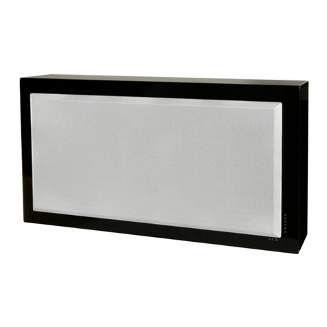
THEORY SB SOUNDBARS Instruction Manual

SB SOUNDBARS
SB MULTI-USE SPEAKERS
Theory sb QUICK START Rev A 191104
QUICK START INSTALLATION
GUIDE
Rev A 191104

LIMITED WARRANTY
Disclaimer : THEORY AUDIO DESIGN, LLC is not liable for any damage to loudspeakers or any other equipment that is caused by negligence
or improper use or installation of this product, including damage caused by connecting Theory loudspeakers and subwoofers to third party ampli-
fiers.
THEORY AUDIO DESIGN, LLC 5-Year Limited Loudspeaker and Subwoofer Warranty
THEORY AUDIO DESIGN, LLC guarantees its loudspeaker and subwoofers products to be free from defective materials and/or workmanship
for a period of five (5) years from the date of sale, and will replace defective parts and/or repair malfunctioning products under this warranty when
the defect occurs under normal installation and use - provided that the unit is returned to our factory or one of our authorized service centers via
prepaid transportation with a copy of proof of purchase (sales receipt). This warranty provides that the examination of the return must indicate, in
our judgment, a manufacturing defect. This warranty does not extend to any product which has been subject to misuse, neglect, accident, improp-
er installation or where the date code has been removed or defaced. THEORY shall not be liable for incidental and/or consequential damages.
The warranty gives you specific legal rights. This limited warranty is not transferable. Customer may have rights which vary from state to state.
In the event that this product was manufactured for export and sale outside of the United States or its territories, then this limited warranty does not
apply. Removal of the serial number on this product, or purchase of this product from an unauthorized dealer will void this limited warranty.
EXCLUSIONS
To the extent permitted by law, the warranty set forth above is in lieu of, and exclusive of, all other warranties, express or implied, and is the sole and
exclusive warranty provided by Theory Audio Design, LLC. All other express and implied warranties, including the implied warranties of merchant-
ability, implied warranty of fitness for use, and implied warranty of fitness for a particular purpose are specifically excluded.
Theory Audio Design, LLC shall not be liable for consequential, incidental, economic, property, bodily injury, or personal injury damages arising
from the product, any breach of this warranty or otherwise.
This warranty statement gives you specific legal rights, and you may have other rights which vary from state to state. Some states do not allow
the exclusion of implied warranties or limitations of remedies, so the above exclusions and limitations may not apply. If your state does not allow
disclaimer of implied warranties, the duration of such implied warranties is limited to period of THEORY’S express warranty
Periodically this warranty is updated. To obtain the most recent version of THEORY’S warranty statement, please call +1-949-245-0505.

QUICK START GUIDE - SB MODELS
IMPORTANT SAFETY INSTRUCTIONS
1. Read all instructions.
2. Keep these instructions.
3. Heed all warnings.
4. Follow all instructions.
5. Do not use this apparatus near water.
6. To prevent fire or shock, do not expose this equipment to moisture or water.
7. Clean only with a dry cloth.
8. Install in accordance with manufacturer’s instructions.
9. Do not install near any heat sources such as radiators, heat registers, stoves or other apparatus that produce heat.
10. Use only attachments/accessories specified by THEORY AUDIO DESIGN, LLC.
11. Use only with hardware, brackets, stands, and components sold with the apparatus or supplied by THEORY AUDIO DESIGN, LLC.
12. Do not install SPEAKERS or SOUNDBARS overhead.
13. Mount only to solid architectural walls.
14. Do not attempt to mount SPEAKERS or SOUNDBARS to your TV or TV mount.
15. Refer all servicing to qualified service personnel. Servicing is required when the apparatus is damaged in any way.
16. Mount Z-CLIP hardware to studs whenever possible. Use drywall anchors only when studs are not available.
17. Connect to Theory or Pro Audio Technology Amplified Loudspeaker Controllers ONLY. Do not connect to third-party amplifiers. Doing so will void the
product warranty and potentially damage the loudspeaker.
Z-CLIP
SPEAKER OR SOUNDBAR
M5 T-SLOT SCREW
DRYWALL ANCHOR SCREW
LAG SCREW
Z-CLIP
DRYWALL ANCHOR
PARTS LIST - SOUNDBARS
1. SOUNDBAR - QTY. 1
2. Z-CLIPS - QTY. 4
3. T-SLOT SCREWS - QTY. 8
4. LAG SCREWS - QTY. 4
5. DRYWALL ANCHORS - QTY. 4
6. DRYWALL ANCHOR SCREWS - QTY. 4
PARTS LIST - MULTI-USE SPEAKERS
1. SPEAKER - QTY. 1
2. Z-CLIPS - QTY. 2
3. T-SLOT SCREWS - QTY. 4
4. LAG SCREWS - QTY. 2
5. DRYWALL ANCHORS - QTY. 2
6. DRYWALL ANCHOR SCREWS - QTY. 2
PARTS LEGEND
PAGE 1

QUICK START GUIDE - SB MODELS
1 - DETERMINE DESIRED POSITION
Use the illustrations in FIGURE 1 as a guide for how you
want to position the SOUNDBAR relative to your TV.
It can be positioned to appear to be mounted to the TV
(FIGURE 1A), or it can be mounted to stand alone beneath
the TV lower edge (FIGURE 1B).
If choosing tight spacing, make sure the TV does not
touch the SOUNDBAR as the vibrations will cause an
audible rattle. Leave a small gap between the TV and the
SOUNDBAR itself. FIGURE 1A. The SOUNDBAR can be
positioned closely to the TV for an integrated
appearance.
FIGURE 1B. The SOUNDBAR can be posi-
tioned with a gap below the TV for an indepen-
dent appearance.
MOUNT TO WALL ONLY - GET HELP
Your Theory SOUNDBAR is heavy and must be mounted
securely to a wall, it cannot be mounted to your TV or TV
mount.
You will need at least three people to safely mount your
SOUNDBAR.
DO NOT TRY TO MOUNT YOUR THEORY
SOUNDBAR BY YOURSELF.
3 - LOCATE STUDS
Next, using a electronic stud finder, locate and mark the stud
locations on your line in between the center and end marks
on both sides. Figure 3.
(Drywall is omitted for clarity).
2 - MARK LOCATION
Using FIGURES 1A and 1B as guide, locate the desired
position of the top center of your SOUNDBAR and make a
small mark on the wall at this location.
Once you’ve located the top center, and using a bubble
or laser level, draw a level line 2.7” below your top-center
mark.
Measure the length of your soundbar and mark the end
points of the SOUNDBAR on the line on either side of the
center mark. FIGURE 2. Place a mark at the desired top
center location. Draw a level line 2.7” below the
center mark the width of your SOUNDBAR.
FIGURE 3. Identify the stud locations and mark
them on your level line.
PAGE 2
SOUNDBAR MODELS

QUICK START GUIDE - SB MODELS
D1 D2
D2
D1
5 - POSITION SOUNDBAR Z-CLIPS
Measure and record the distance from the center mark to
the center of each Z-CLIP. (Figure 5A).
Using a 3mm hex key, loosen the M5 flanged cap screws
on the SOUNDBAR Z-CLIPS and move them into the
positions that correspond with the spacing of the wall
Z-CLIPS. Keep in mind that the spacing will be reversed
when viewing the SOUNDBAR Z-CLIPS from the rear.
(Figure 5B).
Once in place, tighten the M5 bolts to lock the Z-CLIPS in
position. FIGURE 5A. Measure and record the distance
from the center mark to each Z-CLIP
FIGURE 5B. Duplicate Z-CLIP spacing on rear
of your Theory SOUNDBAR keeping in mind
the spacing will be reversed.
4 -MOUNT WALL Z-CLIPS
Using the supplied lag screws and a laser or bubble level,
mount the two supplied Z-CLIPS to one stud on each side
of the center mark, positioning the top edge of the Z-CLIP
on the line according to Figure 4A.
Select studs which are spaced within the ends of the
SOUNDBAR length that are approximately 2/3 or greater
the length of the SOUNDBAR apart. The stud locations
may not be exactly centered on the SOUNDBAR.
Use 2 screws per Z-CLIP: install one first, level the Z-CLIP
and then install the second screw. (Figure 4B).(If studs are
not available, see ALTERNATE STEP4 on PAGE 4)
T-SLOT
POSITIVE TERMINAL
NEGATIVE TERMINAL
7 - CONNECT WIRES
Connecting the wires and hanging the soundbar will require
a MINIMUM OF THREE PEOPLE: one person lifting the
SOUNDBAR at each end, and one person to connect the
speaker wires to the spring terminals on the back side of the
SOUNDBAR while the SOUNDBAR is held in position
near the installation location.
The speaker wires may be placed in the SOUNDBAR
T-SLOTS to hold them in place for convenience.
Connect the wires to the spring terminals observing the
correct polarity. Note that the orientation of the spring
terminals are opposite for LEFT and RIGHT connections.
6 - ROUTE SPEAKER WIRE
If you haven’t already done so, run 3 speaker wires for LEFT,
CENTER and RIGHT speakers to the SOUNDBAR center
location.
Since the Z-CLIPS will position the SOUNDBAR back
surface only 1/4” o the wall surface, flat (“zip cord”) style
speaker wire will be required and will easiest to conceal
behind the SOUNDBAR.
Make sure to label the speaker wires at both ends for LEFT,
CENTER and RIGHT.
FIGURE 6B. Observe correct polarity: RED -
POSITIVE; BLACK -NEGATIVE.
FIGURE 6A. Connect LEFT, CENTER and
RIGHT speaker wires to terminals shown.
FIGURE 4A. Align Z-CLIP center mount holes
with center of studs. (Drywall omitted for clarity).
FIGURE 4B. For each Z-CLIP, install one screw
first, level the Z-CLIP, then install the second
screw.
RIGHT
CENTER
LEFT
PAGE 3

QUICK START GUIDE - SB MODELS
ALTERNATE STEP 4 - STUD UNAVAILABLE
When a stud is not available onto which to mount the wall
Z-CLIPS, use the supplied drywall anchors as shown.
Mark the Z-CLIP outer hole positions on the wall and install
the drywall anchors. (FIGURE ALT4A).
Align the Z-CLIP outer holes with the drywall anchors and
fasten to the wall using the supplied drywall anchor screws.
(FIGURE ALT4B).
SEAT SOUNDBAR CLIP FULLY INTO WALL CLIP
FIGURE ALT4A. Screw drywall anchors into
drywall at Z-CLIP outer hole locations.
FIGURE ALT4B. Using supplied screws, fasten
Z-CLIP to drywall anchors using supplied
screws.
8 -MOUNT SOUNDBAR
Once wires are connected and checked for polarity, posi-
tion the SOUNDBAR such that the SOUNDBAR Z-CLIPS
are tight against the wall surface and directly above the wall
Z-CLIPS. (FIGURE 8A)
NOTE: IF MOUNTING THE SOUNDBAR TIGHT TO
THE TV, YOU MAY NEED TO REMOVE THE TV FROM
THE WALL TO MOUNT THE SOUNDBAR.
Slowly lower the SOUNDBAR until the speaker Z-CLIPS
engage completely into the wall Z-CLIPS. Push down on
the SOUNDBAR to insure the Z-CLIPS are fully engaged.
(FIGURE 8B)
SB MULTI-USE SPEAKERS
Your SB MULTI-USE SPEAKER uses a single Z-CLIP pair
to mount to a wall surface.
The SPEAKER Z-CLIP comes mounted to the speaker in
portrait orientation (FIGURE 9A). For landscape mounting,
the Z-CLIP may be attached to the SPEAKER along the
same T-SLOT (FIGURE 9B).
Follow STEP 4 (or ALTERNATE STEP 4 if a stud is not
available) to mount the wall Z-CLIP to the wall surface at
the desired speaker location.
Follow STEP 8 to mount the SPEAKER to the wall.
(FIGURE 9B)
THEORY AUDIO DESIGN, LLC
25741 Atlantic Ocean Drive, Suite B
Lake Forest, CA 92630
Tel: 949-245-0505
www.theoryaudiodesign.com
© 2019 THEORY AUDIO DESIGN, LLC. All rights reserved.
Theory Audio Design routinely engages in programs to improve, modify and revise its products without notice or obligation. As such, your product may dier
slightly from what is shown in this guide.
FIGURE 8A. Position the soundbar against the
wall and above the wall Z-Clips.
FIGURE 8B. Push down until both Soundbar
Z-Clips seat fully into both wall Z-clips.
FIGURE 9A. SPEAKER Z-CLIP installed in
portrait position. (Factory default).
FIGURE 9B. Using a 3mm hex key, relocate
SPEAKER Z-CLIP to a common T-SLOT,
centered, for landscape orientation.
PAGE 4
MULTI-USE MODELS
This manual suits for next models
1
Table of contents
Other THEORY Speakers manuals
