Thermadyne THERMAL ARC MECA-ARC 40300 User manual

МЕСА-АВС?
40300
300
Amp
Constant
Current
Diesel
Engine-Driven
Welding
Generator
For
the
Following
Specs:
•
6298E-1
IHERMAL
С.
А
THEHMADYNE.
Company
OWNER'S
MANUAL
Number
430429-427
(Rev
-
AA)
Revised
February
21,
2000
THERMAL
ARC
INC.,
TROY,
OHIO
45373-1085,
U.S.A.

430429-427
Table
ої
Contents
CALIFORNIA
Proposition
65
Warning
Diesel
engine
exhaust
and
some
of
its
constituents
are
known
to
the
State
of
California
to
cause
cancer,
birth
defects,
and
other
reproductive
harm.
INTRODUCTION
How
To
Use
This
Manual
...................................
1-1
Equipment
Identification
...................................
1-1
Receipt
ОГЕаціртепі.....................................
1-1
ARC
WELDING
SAFETY
INSTRUCTIONS
AND
WARNINGS
2
DESCRIPTION
OF
EQUIPMENT
3
Generator:
«ooo
eR
Sp
аа
Q.
eens
а
а
wy
br
а
ая
А
АУЗ
3-1
ENNE:
«unterm
tede
A
Reef
Ж
ЫЛЕ
mere
die
ату eoe Mee
ah
б
ра
eut
&
nen
и
3-1
Identification.
1e
e
а
А
Ae
TS
жес
wl
ee
Я
а,
лк
Ge
a
S
3-1
tabulated:
Data
«c
s
er
Ко
Моя
ра
оо
oU.
EES
3-1
Supplementary
Materials
...................................
3-2
Engine
Controls
and
Instruments.
..............................
3-2
Generator
Controls.
о
гэл
а,
ў
DAR
E
ыа
60
RUE
bc
an
RUPEE
3-3
INSTALLATION
|
4
General
Engine
Driven
Welder
Installation
..........................
4-1
Росано
ћи
за
i
ЛАНА
УКУ
лээр
а
ee
БА
S
доб
4-1
Safety:
à
Liu
de
а
ANS
Pen
dicho,
dei
de
РРО
ок
бо
өн
жыр
З
4-1
ndoofinstallation::
xu
Eus
Lana
а
RA
Xon
а
ELE
4-1
Portable
Installation.
x
=
en
bea
ste
op
В
а
аб
Ru
е
EU
RES
а-а
OS
4-1
Initial
Preparation
For
Use
..................................
4-2
Welding:
beads;
а...
9.9
al
qu
Race
diet
аа
ua
S
А
аа
E
Er
4-3
OPERATION
5
Prestarting
Instructions
....................................
5-1
Break-in
Procedures
.....................................
5-2
Prewelding
Instructions
.
.
..................................
5-2
Welding
Z7
eek
US
аа
а
оа
eh
Ass
ЕЛЕ
ое
5-3
stopping
The
Engine:
г
ао
ge
AER
CIDE
IRE
АН
UE
5-3
Storages
-
злої
ns
S
M
suit
Steg
Tan
о
пр
le
i
eb
ed
dpt
tte
о
d
ios
5-3
Adverse
Weather
Precautions
................................
5-3
MAINTENANCE
6
Engine
And
Related
Components
..............................
6-1
Inspection
And
Cleaning
...................................
6-1
Lubrication’.
«uum
а
2
Roy
d
or
a
ют
Y
qe
реа
pus
6-1
August
24,
1998
Page
1
430429-427
Table
of
Contents
TROUBLESHOOTING
PARTS
LIST
Equipment
Identification
.
. .
.
.
..
How
To
Use
This
Parts
List.
.
. .
..
How
To
Select
Recommended
Spares
MATERIAL
SAFETY
DATA
SHEET
DIAGRAMS
ADDENDUM
WARRANTY
Page
2
February
21,
2000
Revised

INTRODUCTION
How
To
Use
This
Manual
This
Owner's
Manual
usually
applies
to
just
the
underlined
specification
or
part
numbers
listed
on
the
cover.
If
none
are
underlined,
they
are
ail
cov-
ered
by
this
manual.
Throughout
this
manual,
the
words
WARNING,
CAUTION,
and
NOTE
may
appear.
Pay
particular
attention
to
the
information
provided
under
these
headings.
These
special
annotations
are
easily
rec-
ognized
as
follows:
WARNING
gives
information
re-
garding
possible
personal
in-
jury.
Warnings
will
be
enclosed
in
a
box
such
as
this.
CAUTION
refers
to
possible
equipment
damage.
Cautions
will
be
shown
in
bold
type.
NOTE
offers
helpful
information
concern-
ing
certain
operating
procedures.
Notes
will
be
shown
in
italics.
Equipment
Identification
The
unit's
identification
number
(specification
or
part
number),
model,
and
serial
number
usually
appear
on
a
nameplate
attached
to
the
control
panel.
In
some
cases,
the
nameplate
may
be
at-
tached
to
the
rear
panel.
Equipment
which
does
not
have
a
control
panel
such
as
gun
and
cable
assem-
blies
are
identified
only
by
the
specification
or
part
number
printed
on
the
shipping
container.
Record
these
numbers
for
future
reference.
430429-427
INTRODUCTION
Receipt
Of
Equipment
When
you
receive
the
equipment,
check
it
against
the
invoice
to
make
sure
it
is
complete
and
inspect
the
equipment
for
possible
damage
due
о
shipping.
Ifthere
is
any
damage,
notify
the
carrier
immediately
to
file
a
claim.
Furnish
complete
information
con-
cerning
damage
claims
or
shipping
errors
to
Thermal
Arc,
Order
Department,
2200
Corporate
Drive,
Troy,
Ohio
45373-1085.
Include
all
equipment
identification
numbers
as
described
above
along
with
a
full
description
of
the
parts
in
error.
Move
the
equipment
to
the
installation
site
before
uncrating
the
unit.
A
lifting
eye
extends
through
the
top
of
the
cabinet
on
most
equipment
to
facilitate
handling
with
a
hoist
or
crane.
Use
care
to
avoid
damaging
the
equipment
when
using
bars,
ham-
mers,
etc.,
to
uncrate
the
unit.
WARNING:
Falling
machine
due
to
lifting
eye
failure
may
cause
death
or
serious
injury.
e
Lifting
device
may
fail
when
overloaded.
е
This
lifting
device
is
designed
to
lift
the
power
source
ONLY.
If
the
machine
is
equipped
with
a
trailer
or
accessories
over
100
pounds,
DO
NOT
LIFT
by
lifting
eyes.
•
Avoid
sudden
jerks,
drops,
or
swinging.
•
Check
lifting
device
components
visually
for
looseness
and
signs
of
metal
fatigue.
e
Before
changing
any
hardware,
check
grade
and
size
of
bolts,
and
replace
with
bolts
of
equal
or
higher
size
and
grade.
Additional
copies
ofthis
manual
may
be
purchased
by
contacting
Thermal
Arc
at
the
address
given
above.
Include
the
Owners
Manual
number
and
equipment
identification
numbers.
August
24,
1998
1-1

430429-427
INTRODUCTION
This
page
intentionally
left
blank.
1-2
August
24,
1998
АВС
WELDING
SAFETY
INSTRUCTIONS
АМО
WARNINGS
instruction
830001
ARC
WELDING
SAFETY
INSTRUCTIONS
AND
WARNINGS
дА
WARNING
ARC
WELDING
can
be
hazardous.
PROTECT
YOURSELF
AND
OTHERS
FROM
POSSIBLE
SERIOUS
INJURY
OR
DEATH.
КЕЕР
CHILDREN
AWAY.
PACEMAKER
WEARERS
KEEP
AWAY
UNTIL
CONSULTING
YOUR
DOCTOR.
DO
NOT
LOSE
THESE
INSTRUCTIONS.
READ
OPERATING/INSTRUC-
TION
MANUAL
BEFORE
INSTALLING,
OPERATING
OR
SERVICING
THIS
EQUIPMENT.
Welding
products
and
welding
processes
can
cause
serious
injury
or
death,
or
damage
to
other
equipment
or
property,
if
the
operator
does
not
strictly
observe
all
safety
rules
and
take
precautionary
actions.
Safe
practices
have
developed
from
past
experience
in
the
use
of
welding
and
cutting.
These
practices
must
be
learned
through
study
and
training
before
using
this
equipment.
Anyone
not
having
extensive
training
in
welding
and
cutting
practices
should
not
attempt
to
weld.
Certain
of
the
practices
apply
to
equipment
connected
to
power
lines;
other
practices
apply
to
engine
driven
equipment.
Safe
practices
are
outlined
in
the
American
National
Standard
Z49.1
entitled:
SAFETY
IN
WELDING
AND
CUTTING.
This
publication
and
other
guídes
to
what
you
should
learn
before
operating
this
equipment
are
listed
at
the
end
of
these
safety
precautions.
HAVE
ALL
INSTALLATION,
OPERATION,
MAINTENANCE,
AND
REPAIR
WORK
PERFORMED
ONLY
BY
QUALIFIED
PEOPLE.
.
ELECTRIC
SHOCK
can
kill.
Touching
live
electrical
parts
can
cause
fatal
shocks
or
severe
burns.
The
electrode
and
work
circuit
is
electrically
live
whenever
the
output
is
on.
The
input
power
circuit
and
machine
internal
circuits
are
also
live
when
power
is
on.
In
semiautomatic
or
auto-
matic
wire
welding,
the
wire,
wire
reel,
drive
roll
housing,
and
all
metal
parts
touching
the
welding
wire
are
electrically
live.
Incorrectly
installed
or
im-
properly
grounded
equipment
is
a
hazard.
.
Do
not
touch
live
electrical
parts.
.
Wear
dry,
hole-free
insulating
gloves
and
body
protection.
.
Insulate
yourself
from
work
and
ground
using
dry
insulating
mats
or
covers.
.
Disconnect
input
power
or
stop
engine
before
installing
or
servicing
this
equipment.
Lock
input
power
disconnect
switch
open,
or
remove
line
fuses
so
power
cannot
be
turned
on
accidentally.
.
Properly
install
and
ground
this
equipment
according
to
its
Owner's
Manual
and
national,
state,
and
local
codes.
ARC
RAYS
can
burn
eyes
and
skin;
NOISE
can
damage
hearing.
Arc
rays
from
the
welding
process
produce
intense
heat
and
strong
ultraviolet
rays
that
can
burn
eyes
and
skin.
Noise
from
some
processes
can
damage
hearing.
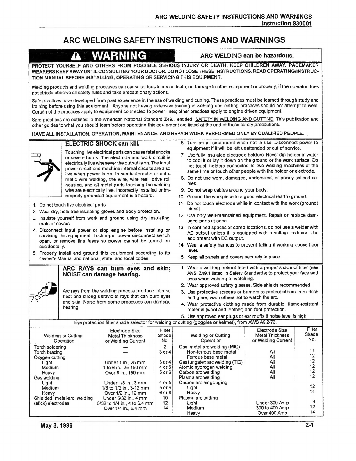
Electrode
Size
Filter
||
Welding
or
Cutting
Metal
Thickness
Shade
Operation
or
Welding
Current
No.
Torch
soldering
—
2
Torch
brazing
—
3or4
Oxygen
cutting
Gas
metal-arc
welding
(MIG)
.
Turn
off
а!
equipment
when
not
in
use.
Disconnect
power
to
equipment
if
it
will
be
left
unattended
or
out
of
service.
.
Use
fully
insulated
electrode
holders.
Never
dip
holder
in
water
to
cool
it
or
lay
it
down
on
the
ground
or
the
work
surface.
Do
not
touch
holders
connected
to
two
welding
machines
at
the
same
time
or
touch
other
people
with
the
holder
or
electrode.
.
Do
not
use
worn,
damaged,
undersized,
or
poorly
spliced
ca-
bles.
.
Do
not
wrap
cables
around
your
body.
.
Ground
the
workpiece
to
a
good
electrical
(earth)
ground.
.
Do
not
touch
electrode
while
in
contact
with
the
work
(ground)
circuit.
.
Use
only
well-maintained
equipment.
Repair
or
replace
dam-
aged
parts
at
once.
.
In
confined
spaces
or
damp
locations,
do
not
use
a
welder
with
AC
output
unless
it
is
equipped
with
a
voltage
reducer.
Use
equipment
with
DC
output.
.
Wear
a
safety
harness
to
prevent
falling
if
working
above
floor
level.
.
Keep
all
panels
and
covers
securely
in
place.
.
Wear
a
welding
helmet
fitted
with
a
proper
shade
of
filter
(see
ANSI
249.1
listed
in
Safety
Standards)
to
protect
your
face
and
eyes
when
welding
or
watching.
.
Wear
approved
safety
glasses.
Side
shields
recommended.
.
Use
protective
screens
or
barriers
to
protect
others
from
flash
and
glare;
warn
others
not
to
watch
the
arc.
.
Wear
protective
clothing
made
from
durable,
flame-resistant
material
(wool
and
leather)
and
foot
protection.
.
Use
approved
ear
plugs
or
ear
muffs
if
noise
level
is
high.
Electrode
Size
Welding
or
Cutting
Metal
Thickness
Operation
or
Welding
Current
Non-ferrous
base
metal
АН
Ferrous
base
metal
Al
Light
Underiin,25mm
|
3or4|
Medium
1t06in.,25-150mm
|
40г5||
Неауу
Over
б
іп.,
150
тт
5076
Gas
welding
Plasma
arc
welding
|
АЙ
Light
Under
1/8
in.,
З
тт
4075|
Carbon
arc
air
gouging
Medium
1/8
to
1/2
in.,
3-12
mm
5or6
Light
Heavy
|
Оуег
1/2
іп.,
12
тт
6
or
8],
Heavy
Shielded
metal-arc
welding
Under
5/32
іп.,
4
тт
10
|
Plasma
arc
cutting
(stick)
electrodes
5/32
to
1/4
in.,
410
6.4
тт
12
Light
Under
300
Amp
|
Over
1/4
in.,
6.4
mm
14
Medium
300
to
400
Amp
|
|
Неауу
Over
400
Amp
Gas
tungsten
arc
welding
(TIG)
АІ
Atomic
hydrogen
welding
All
Carbon
arc
welding
Al
May
8,
1996
2-1
АВС
WELDING
SAFETY
INSTRUCTIONS
AND
WARNINGS
Instruction
830001
FUMES
AND
GASES
can
be
hazardous
to
your
health.
Welding
produces
fumes
and
gases.
Breathing
these
fumes
and
gases
can
be
hazardous
to
your
health.
.
Keep
your
head
out
of
the
fumes.
Do
not
breath
the
fumes.
.
Е
inside,
ventilate
the
area
and/or
use
exhaust
at
the
arc
to
remove
welding
fumes
and
gases.
.
Kf
ventilation
is
poor,
use
an
approved
air-supplied
respirator.
WELDING
can
cause
fire
or
explosion.
Sparks
and
spatter
fly
off
from
the
welding
arc.
The
flying
sparks
and
hot
metal,
weld
spatter,
hot
work-
piece,
and
hot
equipment
can
cause
fires
and
burns.
Accidental
contact
of
electrode
or
welding
wire
to
metal
objects
can
cause
sparks,
overheating,
or
fire.
.
Protect
yourself
and
others
from
flying
sparks
and
hot
metal.
.
Do
not
weld
where
flying
sparks
can
strike
flammable
material.
.
Remove
all
flammables
within
35
ft
(10.7
m)
of
the
welding
arc.
If
this
is
not
possible,
tightly
cover
them
with
approved
covers.
.
Bealertthat
welding
sparks
and
hot
materials
from
welding
can
easily
go
through
small
cracks
and
openings
to
adjacent
areas.
FLYING
SPARKS
AND
HOT
METAL
can
cause
injury.
Chipping
and
grinding
cause
flying
metal.
As
welds
cool,
they
can
throw
off
slag.
CYLINDERS
can
explode
if
damaged.
Shielding
gas
cylinders
contain
gas
underhigh
pres-
sure.
If
damaged,
a
cylinder
can
explode.
Since
gas
cylinders
are
normally
part
of
the
welding
process,
be
sure
to
treat
them
carefully.
.
Protect
compressed
gas
cylinders
from
excessive
heat,
me-
chanical
shocks,
and
arcs.
.
Install
and
secure
cylinders
in
an
upright
position
by
chaining
them
to
a
stationary
support
or
equipment
cylinder
rack
to
prevent
falling
or
tipping.
&
WARNING
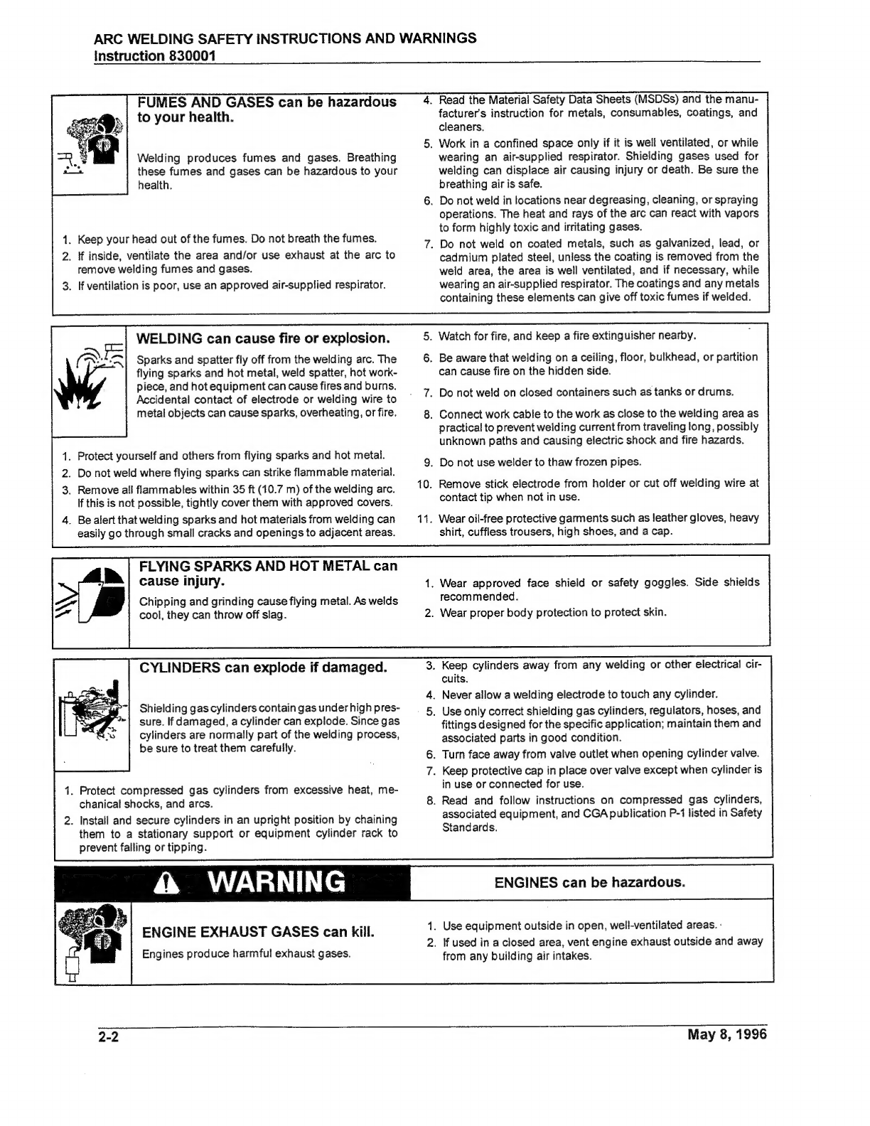
ENGINE
EXHAUST
GASES
can
kill.
Engines
produce
harmful
exhaust
gases.
2-2
.
Read
the
Material
Safety
Data
Sheets
(MSDSs)
and
the
manu-
facturer's
instruction
for
metals,
consumables,
coatings,
and
cleaners.
‚
Work
in
a
confined
space
only
if
it
is
well
ventilated,
or
while
wearing
an
air-supplied
respirator.
Shielding
gases
used
for
welding
can
displace
air
causing
injury
or
death.
Be
sure
the
breathing
air
is
safe.
.
Do
not
weld
in
locations
near
degreasing,
cleaning,
or
spraying
operations.
The
heat
and
rays
of
the
arc
can
react
with
vapors
to
form
highly
toxic
and
irritating
gases.
.
Do
not
weld
on
coated
metals,
such
as
galvanized,
lead,
or
cadmium
plated
steel,
unless
the
coating
is
removed
from
the
weld
area,
the
area
is
well
ventilated,
and
if
necessary,
while
wearing
an
air-supplied
respirator.
The
coatings
and
any
metals
containing
these
elements
can
give
off
toxic
fumes
if
welded.
5.
Watch
for
fire,
and
keep
a
fire
extinguisher
nearby.
6.
Be
aware
that
welding
on
a
ceiling,
floor,
bulkhead,
or
partition
can
cause
fire
on
the
hidden
side.
.
Do
not
weld
on
closed
containers
such
as
tanks
or
drums.
.
Connect
work
cable
to
the
work
as
close
to
the
welding
area
as
practical
to
prevent
welding
current
from
traveling
long,
possibly
unknown
paths
and
causing
electric
shock
and
fire
hazards.
.
Do
not
use
welder
to
thaw
frozen
pipes.
.
Remove
stick
electrode
from
holder
or
cut
off
welding
wire
at
contact
tip
when
not
in
use.
.
Wear
oil-free
protective
garments
such
as
leather
gloves,
heavy
shirt,
cuffless
trousers,
high
shoes,
and
a
cap.
.
Wear
approved
face
shield
or
safety
goggles.
Side
shields
recommended.
.
Wear
proper
body
protection
to
protect
skin.
.
Keep
cylinders
away
from
any
welding
or
other
electrical
cir-
cuits.
.
Never
allow
a
welding
electrode
to
touch
any
cylinder.
.
Use
only
correct
shielding
gas
cylinders,
regulators,
hoses,
and
fittings
designed
for
the
specific
application;
maintain
them
and
associated
parts
in
good
condition.
.
Turn
face
away
from
valve
outlet
when
opening
cylinder
valve.
.
Keep
protective
cap
in
place
over
valve
except
when
cylinder
is
in
use
or
connected
for
use.
.
Read
and
follow
instructions
on
compressed
gas
cylinders,
associated
equipment,
and
CGA
publication
P-1
listed
in
Safety
Standards.
ENGINES
can
be
hazardous.
1.
Use
equipment
outside
in
open,
well-ventilated
areas.
·
2.
If
used
in
a
closed
area,
vent
engine
exhaust
outside
and
away
from
any
building
air
intakes.
May
8,
1996
ARC
WELDING
SAFETY
INSTRUCTIONS
AND
WARNINGS
Instruction
830001
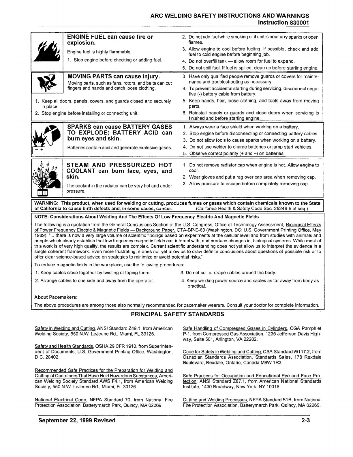
ENGINE
FUEL
can
cause
fire
or
explosion.
Engine
fuel
is
highly
flammable.
1.
Stop
engine
before
checking
or
adding
fuel.
MOVING
PARTS
can
cause
injury.
Moving
parts,
such
as
fans,
rotors,
and
belts
can
cut
fingers
and
hands
and
catch loose
clothing.
1.
Keep
all
doors,
panels,
covers,
and
guards
closed
and
securely
in
place.
2.
Stop
engine
before
installing
or
connecting
unit.
SPARKS
can
cause
BATTERY
GASES
TO
EXPLODE;
BATTERY
ACID
can
burn
eyes
and
skin.
Batteries
contain
acid
and
generate
explosive
gases.
STEAM
AND
PRESSURIZED
HOT
COOLANT
can
burn
face,
eyes,
and
skin.
The
coolant
in
the
radiator
can
be
very
hot
and
under
pressure.
.
Do
not
add
fuel
while
smoking
or
if
unit
is
near
any
sparks
or
open
flames.
.
Allow
engine
to
cool
before
fueling.
If
possible,
check
and add
fuel
to
cold
engine
before
beginning
job.
.
Do
not
overfill
tank
—
allow
room
for
fuel
to
expand.
.
Do
not
spill
fuel.
If
fuel
is
spilled,
clean
up
before
starting
engine.
.
Have
only
qualified
people
remove
guards
or
covers
for
mainte-
nance
and
troubleshooting
as
necessary.
.
To
prevent
accidental
starting
during
servicing,
disconnect
nega-
tive
(-)
battery
cable
from
battery.
.
Keep
hands,
hair,
loose
clothing,
and
tools
away
from
moving
parts.
.
Reinstall
panels
or
guards
and
close
doors
when
servicing
is
finished
and
before
starting
engine.
.
Always
wear
a
face
shield
when
working
on
a
battery.
.
Stop
engine
before
disconnecting
or
connecting
battery
cables.
.
Do
not
allow
tools
to
cause
sparks
when
working
on
a
battery.
.
Do
not
use
welder
to
charge
batteries
or
jump
start
vehicles.
.
Observe
correct
polarity
(+
and
—)
on
batteries.
.
Do
not
remove
radiator
cap
when
engine
is
hot.
Allow
engine
to
cool.
.
Wear
gloves
and
put
a
rag
over
cap
area
when
removing
cap.
.
Allow
pressure
to
escape
before
completely
removing
cap.
WARNING:
This
product,
when
used
for
welding
or
cutting,
produces
fumes
or
gases
which
contain
chemicals
known
to
the
State
of
California
to
cause
birth
defects
and,
in
some
cases,
cancer.
(California
Health
&
Safety
Code
Sec.
25249.5
et
seq.)
NOTE:
Considerations
About
Welding
And
The
Effects
Of
Low
Frequency
Electric
And
Magnetic
Fields
The
following
is
a
quotation
from
the
General
Conclusions
Section
of
the
U.S.
Congress,
Office
of
Technology
Assessment,
Biological
Effects
of
Power
Frequency
Electric
&
Magnetic
Fields
—
Background
Paper,
OTA-BP-E-63
(Washington,
DC:
U.S.
Government
Printing
Office,
May
1989):
“...
there
is
now
a
very
large
volume
of
scientific
findings
based
on
experiments
at
the
cellular
level
and
from
studies
with
animals
and
people
which
clearly
establish
that
low
frequency
magnetic
fields
can
interact
with,
and
produce
changes
in,
biological
systems.
While
most
of
this
work
is
of
very
high
quality,
the
results
are
complex.
Current
scientific
understanding
does
not
yet
allow
us
to
interpret
the
evidence
in
a
single
coherent
framework.
Even
more
frustrating,
it
does
not
yet
allow
us
to
draw
definite
conclusions
about
questions
of
possible
risk
or
to
offer
clear
science-based
advice
on
strategies
to
minimize
or
avoid
potential
risks."
To
reduce
magnetic
fields
in
the
workplace,
use
the
following
procedures:
1.
Keep
cables
close
together
by
twisting
or
taping
them.
3.
Do
not
coil
or
drape
cables
around
the
body.
2.
Arrange
cables
to
one
side
and
away
from
the
operator.
4.
Keep
welding
power
source
and
cables
as
far
away
from
body
as
practical.
About
Pacemakers:
The
above
procedures
are
among
those
also
normally
recommended
for
pacemaker
wearers.
Consult
your
doctor
for
complete
information.
PRINCIPAL
SAFETY
STANDARDS
Safety
in
Welding
and
Cutting,
ANSI
Standard
Z49.1,
from
American
Safe
Handling
of
Compressed
Gases
in
Cylinders,
CGA
Pamphlet
Welding
Society,
550
N.W.
LeJeune
Rd.,
Miami,
FL
33126.
P-1,
from
Compressed
Gas
Association,
1235
Jefferson
Davis
High-
way,
Suite
501,
Arlington,
VA
22202.
Safety
and
Health
Standards,
OSHA
29
CFR
1910,
from
Superinten-
dent
of
Documents,
U.S.
Government
Printing
Office,
Washington,
D.C.
20402.
Code
for
Safety
in
Welding
and
Cutting,
CSA
Standard
W1
17.2,
from
Canadian
Standards
Association,
Standards
Sales,
178
Rexdale
Boulevard,
Rexdale,
Ontario,
Canada
M9W
1R3.
Recommended
Safe
Practices
for
the
Preparation
for
Welding
and
Cutting
of
Containers
That
Have
Held
Hazardous
Substances,
Ameri-
can
Welding
Society
Standard
AWS
F4.1,
from
American
Welding
Society,
550
N.W.
LeJeune
Rd.,
Miami,
FL
33126.
Safe
Practices
for
Occupation
and
Educational
Eye
and
Face
Pro-
tection,
ANSI
Standard
Z87.1,
from
American
National
Standards
Institute,
1430
Broadway,
New
York,
NY
10018.
Nationa!
Electrical
Code,
NFPA
Standard
70,
from
National
Fire
Protection
Association,
Batterymarch
Park,
Quincy,
MA
02269.
Cutting
and
Welding
Processes,
NFPA
Standard
51B,
from
National
Fire
Protection
Association,
Batterymarch
Park,
Quincy,
MA
02269.
September
22,
1999
Revised
2-3

АВС
WELDING
SAFETY
INSTRUCTIONS
AND
WARNINGS
Instruction
830001
This
page
intentionally
left
blank.
2-4
Мау
8,
1996

PRECAUTIONS
ОЕ
SECURITE
ЕМ
SOUDAGE
А
L'ARC
Instruction
830002
PRECAUTIONS
DE
SECURITE
EN
SOUDAGE
AL
ARC
MISE
ЕМ
GARDE
LE
SOUDAGE
A
L'ARC
EST
DANGEREUX
PROTEGEZ-VOUS,
AINSI
QUE
LES
AUTRES,
CONTRE
LES
BLESSURES
GRAVES
POSSIBLES
OÙ
LA
MORT.
NE
LAISSEZ
PAS
LES
ENFANTS
S'APPROCHER,
NI
LES
PORTEURS
DE
STIMULATEUR
CARDIAQUE
(A
MOINS
QU'ILS
N'AIENT
CONSULTE
UN
MEDECIN).
CONSERVEZ
CES
INSTRUCTIONS.
LISEZ
LE
MANUEL
D'OPERATION
OU
LES
INSTRUCTIONS
AVANT
D'INSTALLER,
UTILISER
OU
ENTRETENIR
CET
EQUIPEMENT.
Les
produits
et
procédés
de
soudage
peuvent
sauser
des
blessures
graves
ou
la
mort,
de
тёте
que
des
dommages
au
reste
du
matériel
et
à
la
propriété,
si
l'utilisateur
n'adhére
pas
strictement
à
toutes
les
régles
de
sécurité
et
ne
prend
pas
les
précautions
nécessaires.
En
soudage
et
coupage,
des
pratiques
sécuritaires
se
sont
développées
suite
à
l'expérience
passée.
Ces
pratiques
doivent
étre
apprises
par
étude
ou
entrainement
avant
d'utiliser
l'equipement.
Toute
personne
n'ayant
pas
suivi
un
entrainement
intensif
en
soudage
et
coupage
ne
devrait
pas
tenter
de
souder.
Certaines
pratiques
concernent
les
équipements
raccordés
aux
lignes
d'alimentation
alors
que
d'autres
s'adressent
aux
groupes
électrogènes.
La
norme
249.1
de
l'American
National
Standard,
intitulée
"SAFETY
IN
WELDING
AND
CUTTING"
présente
les
pratiques
sécuritaires
а
suivre.
Ce
document
ainsi
que
d'autres
guides
que
vous
devriez
connaitre
avant
d'utiliser
cet
équipement
sont
présentés
à
la
fin
de
ces
instructions
de
sécurité.
SEULES
DES
PERSONNES
QUALIFIEES
DOIVENT
FAIRE
DES
TRAVAUX
D'INSTALLATION,
DE
REPARATION,
D'ENTRETIEN
ET
D'ESSAI.
.
Arrétez
tout
équipement
aprés
usage.
Coupez
l'alimentation
de
l'équipement
s'il
est
hors
d'usage
ou
inutilisé.
7.
N'utilisez
que
des
porte-électrodes
bien
isolés.
Ne
jamais
plon-
ger
les
porte-électrodes
dans
l'eau
pour
les
refroidir.
Ne
jamais
les
laisser
trainer
par
terre
ou
sur
les
pièces
à
souder.
Ne
touchez
pas
aux
porte-électrodes
raccordés
à
deux
sources
de
courant
en
méme
temps.
Ne
jamais
toucher
quelqu'un
d'autre
avec
l'électrode
ou
le
porte-électrode.
8.
N'utilisez
pas
de
câbles
électriques
usés,
endommagés,
та!
épissés
ou
de
section
trop
petite.
N'enroulez
pas
de
câbles
électriques
autour
de
votre
corps.
N'utilisez
qu'une
bonne
prise
de
masse
pour
la
mise
à
la
terre
de
la
piéce
à
souder.
Ne
touchez
pas
à
l'électrode
lorsqu'en
contact
avec
le
circuit
de
soudage
(terre).
12.
N'utilisez
que
des
équipements
en
bon
état.
Réparez
ou
rem-
L'ELECTROCUTION
PEUT
ETRE
MORTELLE.
Une
décharge
électrique
peut
tuer
ou
brüler
grave-
ment.
L'électrode
et
le
circuit
de
soudage
sont
sous
tension
dés
la
mise
en
circuit.
Le
circuit
d'alimenta-
tion
et
les
circuits
internes
de
l'équipement
sont
aussi
sous
tension
dés
la
mise
en
marche.
En
soudage
automatique
ou
semi-automatique
avec
fil,
ce
dernier,
le
rouleau
ou
la
bobine
de
fil,
le
logement
des
galets
d'entrainement
et
toutes
les
pièces
métalliques
en
contact
avec
le
fil
de
soudage
9.
sont
sous
tension.
Un
équipement
inadéquatement
|
10.
installé
ou
inadéquatement
mis
à
la
terre
est
dangereux.
1.
Ne
touchez
pas
à
des
piéces
sous
tension.
11.
2.
Portez
des
gants
et
des
vétements
isolants,
secs
et
non
troués.
3.
Isolez-vous
de
la
pièce
à
souder
et
dela
mise
а
la
terre
au
moyen
de
tapis
isolants
ou
autres.
placez
aussitôt
les
pièces
endommagées.
.
Déconnectez
la
prise
d'alimentation
de
l'équipement
ou
arrêtez
13.
Dans
des
espaces
confinés
ou
mouillés,
n'utilisez
pas
de
source
le
moteur
avant
de
l'installer
ou
d'en
faire
l'entretien.
Bloquez
le
de
courant
alternatif,
à
moins
qu'il
soit
muni
d'un
réducteur
de
commutateur
en
circuit
ouvert
ou
enlevez
les
fusibles
de
tali-
tension.
Utilisez
plutót
une
source
de
courant
continu.
mentation
afin
d'éviter
une
mise
en
marche
accidentelle.
14.
Portez
un
harnais
de
sécurité
si
vous
travaillez
en
hauteur.
.
Veuillez
à
installer
cet
équipement
et
à
le
mettre
à
la
terre
selon
15.
Fermez
solidement
tous
les
panneaux
et
les
capots.
le
manuel
d'utilisation
et
les
codes
nationaux,
provinciaux
et
locaux
applicables.
LE
RAYONNEMENT
DE
L'ARC
PEUT
1.
Portez
une
casque
de
soudeur
avec
filtre
oculaire
de
nuance
appropriée
(consultez
la
norme
ANSI
Z49
indiquée
ci-aprés)
8-V-96
pour
vous
protéger
le
visage
et
les
yeux
lorsque
vous
soudez
ou
que
vous
observez
l'exécution
d'une
soudure.
BRÜLER
LES
YEUX
ET
LA PE
AU;
LE
2.
це
Ене
ae
34
sécurité
approuvées.
Des
écrans
latéraux
,
BRUIT
PEUTENDOMMAGERL'OUIE.
3.
Entourez
l'aire
de
soudage
de
rideaux
ou
de
cloisons
pour
L'arc
de
soudage
produit
une
chaleur
et
des
protéger
les
autres
des
coups
d'arc
ou
de
l'éblouissement;
rayons
ultraviolets
intenses,
susceptibles
de
avertissez
les
observateurs
de
ne
pas
regarder
l'arc.
brüler
les
yeux
et
la
peau.
Le
bruit
causé
par
4.
Portez
des
vétements
en
matériaux
ignifuges
et
durables
(laine
certains
procédés
peut
endommager
l'ouie.
et
cuir)
et
des
chaussures
de
sécurité.
5.
Portez
un
casque
antibruit
ou
des
bouchons
d'oreille
approuvés
lorsque
le
niveau
de
bruit
est
élevé.
2-1

PRECAUTIONS
ОЕ
SECURITE
ЕМ
SOUDAGE
А
ГАВС
Instruction
830002
SELECTION
DES
NUANCES
РЕ
FILTRES
OCULAIRES
POUR
LA
PROTECTION
DES
YEUX
ЕМ
COUPAGE
ЕТ
SOUDAGE
(selon
AWS
А
8.2-73
)
Opération
de
Coupage
ou
soudage
Brasage
tendre
au
chalumeau
Brasage
fort
au
chalumeau
Oxycoupage
mince
moyen
épais
Soudage
aux
gaz
mince
moyen
épais
Soudage
à
Рагс
avec
electrode
enrobées
(SMAW)
Soudage
à
l'arc
sous
gaz
avec
fil
plein
(GMAW)
métaux
non-ferreux
métaux
ferreux
Soudage
à
l'arc
sous
gaz
avec
électrode
de
tungstène
(GTAW)
Soudage
à
l'hydrogène
atomique
(AHW)
Soudage
à
Гагс
avec
électrode
de
carbone
(CAW)
Soudage
à
l'arc
Plasma
(РАМУ)
Gougeage
Аіг-Агс
avec
électrode
de
carbone
mince
épais
Coupage
à
l'arc
Plasma
(PAC)
mince
moyen
épais
Dimension
d'électrode
ou
Epaisseur
de
métal
ou
Intensité
de
courant
toutes
conditions
moins
de
1
po.
(25
mm)
de
1
à 6
po.
(25
а
150
mm)
plus
de
6
po.
(150
mm)
moins
de
1/8
po.
(3
mm)
de
1/8
à
1/2
po.
(За
12
mm)
plus
de
1/2
ро.
(12
тт)
moins
де
5/32
ро.
(4
тт)
де
5/32
а
1/4
ро.
(4
а
6.4
тт)
plus
de
1/4
ро.
(6.4
тт)
toutes
conditions
toutes
conditions
toutes
conditions
toutes
conditions
toutes
conditions
toutes
dimensions
moins
de
300
ampères
de
300
à
400
ampères
plus
de
400
ampères
Nuance
de
de
filtre
oculaire
LES
VAPEURS
ET
LES
FUMEES
SONT
DANGEREUSES
POUR
LA
SANTE.
Le
soudage
dégage
des
vapeurs
et
des
fumées
dangereuses
à
respirer.
1.
Eloignez
la
tête
des
fumées
pour
éviter
de
les
respirer.
2.
A
l'intérieur,
assurez-vous
que
l'aire
de
soudage
est
bien
ven-
tilée
ou
que
les
fumées
et
les
vapeurs
sont
aspirées
à
l'arc.
3.
Si
la
ventilation
est
inadequate,
portez
un
respirateur
à
adduc-
tion
d'air
approuvé.
4.
Lisez
les
fiches
signalétiques
et
les
consignes
du
fabricant
relatives
aux
métaux,
aux
produits
consummables,
aux
revéte-
ments
et
aux
produits
nettoyants.
5.
Ne
travaillez
dans
un
espace
confiné
que
s'il
est
bien
ventilé;
sinon,
portez
un
respirateur
à
adduction
d'air.
Les
gaz
protec-
teurs
de
soudage
peuvent
déplacer
Гохудёпе
de
l'air
et
ainsi
causer
des
malaises
ou
la
mort.
Assurez-vous
que
l'air
est
propre
à
la
respiration.
6.
Ne
soudez
pas
à
proximité
d'opérations
de
dégraissage,
de
nettoyage
ou
de
pulvérisation.
La
chaleur
et
les
rayons
de
l'arc
peuvent
réagir
avec
des
vapeurs
et
former
des
gaz
hautement
toxiques
et
irritants.
7.
Ne
soudez
des
tóles
galvanisées
ou
plaquées
au
plomb
ou
au
cadmium
que
si
les
zones
à
souder
ont
été
grattées
à
fond,
que
51
l'espace
est
bien
ventilé;
si
nécessaire
portez
un
respirateur
à
adduction
d'air.
Car
ces
revétements
et
tout
métal
qui
con-
tient
ces
éléments
peuvent
dégager
des
fumées
toxiques
au
moment
du
soudage.
8-V-96
PRECAUTIONS
DE
SECURITE
EN
SOUDAGE
A
L'ARC
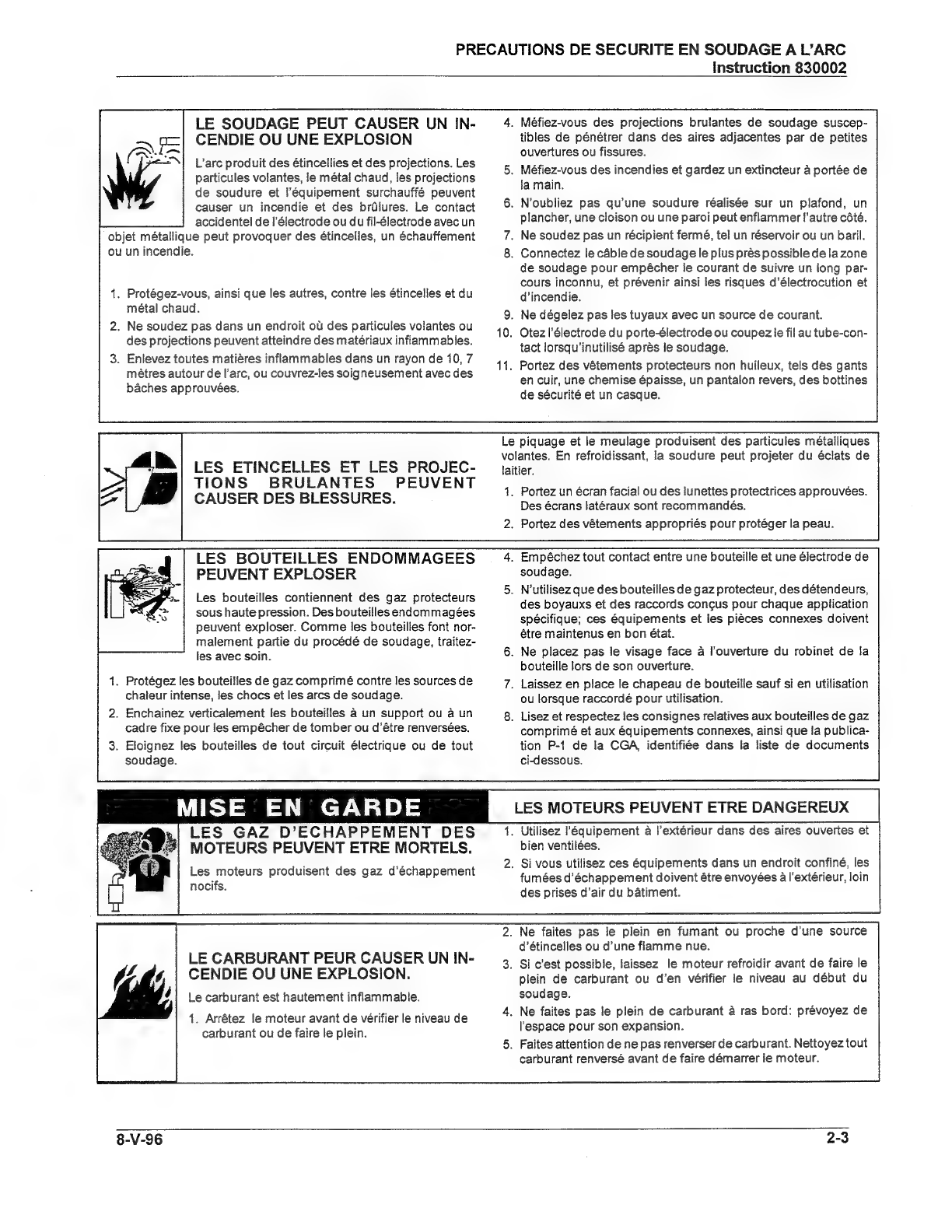
LE
SOUDAGE
PEUT
CAUSER
UN
IN-
CENDIE
OU
UNE
EXPLOSION
L'arc
produit
des
étincellies
et
des
projections.
Les
particules
volantes,
ie
métal
chaud,
les
projections
de
soudure
et
l'équipement
surchauffé
peuvent
causer
un
incendie
et
des
brülures.
Le
contact
accidentel
de
l'électrode
ou
du
fil-électrode
avec
un
objet
métallique
peut
provoquer
des
étincelles,
un
échauffement
ou
un
incendie.
.
Protégez-vous,
ainsi
que
les
autres,
contre
les
étincelles
et
du
métal
chaud.
.
Ne
soudez
pas
dans
un
endroit
oü
des
particules
volantes
ou
des
projections
peuvent
atteindre
des
matériaux
inflammables.
.
Enlevez
toutes
matières
inflammables
dans
un
rayon
de
10,
7
mètres
autour
de
l'arc,
ou
couvrez-les
soigneusement
avec
des
báches
approuvées.
LES
ETINCELLES
ET
LES
PROJEC-
TIONS
BRULANTES
PEUVENT
CAUSER
DES
BLESSURES.
LES
BOUTEILLES
ENDOMMAGEES
PEUVENT
EXPLOSER
Les
bouteilles
contiennent
des
gaz
protecteurs
sous
haute
pression.
Des
bouteilles
endommagées
peuvent
exploser.
Comme
les
bouteilles
font
nor-
malement
partie
du
procédé
de
soudage,
traitez-
les
avec
soin.
1.
Protégez
les
bouteilles
de
gaz
comprimé
contre
les
sources
de
chaleur
intense,
les
chocs
et
les
arcs
de
soudage.
2.
Enchainez
verticalement
les
bouteilles
a
un
support
ou
а
un
cadre
fixe
pour
les
empécher
de
tomber
ou
d’étre
renversées.
3.
Eloignez
les
bouteilles
de
tout
circuit
électrique
ou
de
tout
soudage.
MISE
EN
GARDE
LES
GAZ
D’ECHAPPEMENT
DES
MOTEURS
PEUVENT
ETRE
MORTELS.
Les
moteurs
produisent
des
gaz
d’échappement
nocifs.
LE
CARBURANT
PEUR
CAUSER
UN
IN-
CENDIE
OU
UNE
EXPLOSION.
Le
carburant
est
hautement
inflammable.
1.
Arrêtez
le
moteur
avant
de
vérifier
le
niveau
de
carburant
ou
de
faire
le
plein.
Instruction
830002
.
Méfiez-vous
des
projections
brulantes
de
soudage
suscep-
tibles
de
pénétrer
dans
des
aires
adjacentes
par
de
petites
ouvertures
ou
fissures.
.
Méfiez-vous
des
incendies
et
gardez
un
extincteur
a
portée
de
ја
main.
.
N'oubliez
pas
qu'une
soudure
réalisée
sur
un
plafond,
un
plancher,
une
cloison
ou
une
paroi
peut
enflammer
l'autre
côté.
.
Ne
soudez
pas
un
récipient
fermé,
tel
un
réservoir
ou
un
baril.
.
Connectez
le
câble
de
soudage
le
plus
près
possible
de
la
zone
de
soudage
pour
empêcher
le
courant
de
suivre
un
long
par-
cours
inconnu,
et
prévenir
ainsi
les
risques
d'électrocution
et
d'incendie.
.
Ne
dégelez
pas
les
tuyaux
avec
un
source
de
courant.
.
Otezl'électrode
du
porte-électrode
ou
coupez
le
fil
au
tube-con-
tact
lorsqu'inutilisé
apres
le
soudage.
.
Portez
des
vêtements
protecteurs
non
huileux,
tels
dès
gants
en
cuir,
une
chemise
épaisse,
un
pantalon
revers,
des
bottines
de
sécurité
et
un
casque.
Le
piquage
et
le
meulage
produisent
des
particules
métalliques
volantes.
En
refroidissant,
la
soudure
peut
projeter
du
éclats
de
laitier.
.
Portez
un
écran
facial
ou
des
lunettes
protectrices
approuvées.
Des
écrans
latéraux
sont
recommandés.
.
Portez
des
vétements
appropriés
pour
protéger
la
peau.
.
Empéchez
tout
contact
entre
une
bouteille
et
une
électrode
de
soudage.
5.
N'utilisez
que
des
bouteilles
de
gaz
protecteur,
des
détendeurs,
des
boyauxs
et
des
raccords
congus
pour
chaque
application
spécifique;
ces
équipements
et
les
piéces
connexes
doivent
étre
maintenus
en
bon
état.
6.
Ne
placez
pas
le
visage
face
à
l'ouverture
du
robinet
de
la
bouteille
lors
de
son
ouverture.
7.
Laissez
en
place
le
chapeau
de
bouteille
sauf
si
en
utilisation
ou
lorsque
raccordé
pour
utilisation.
8.
Lisez
et
respectez
les
consignes
relatives
aux
bouteilles
de
gaz
comprimé
et
aux
équipements
connexes,
ainsi
que
la
publica-
Чоп
P-1
de
la
СВА,
identifiée
dans
la
liste
de
documents
ci-dessous.
LES
MOTEURS
PEUVENT
ETRE
DANGEREUX
.
Utilisez
l'équipement
à
l'extérieur
dans
des
aires
ouvertes
et
bien
ventilées.
.
Si
vous
utilisez
ces
équipements
dans
un
endroit
confiné,
les
fumées
d'échappement
doivent
étre
envoyées
à
l'extérieur,
loin
des
prises
d'air
du
bátiment.
.
Ne
faites
pas
le
plein
en
fumant
ou
proche
d'une
source
d'étincelles
ou
d'une
flamme
nue.
3.
Si
c'est
possible,
laissez
le
moteur
refroidir
avant
de
faire
le
plein
de
carburant
ou
d'en
vérifier
le
niveau
au
début
du
soudage.
4.
Ne
faites
pas
le
plein
de
carburant
à
ras
bord:
prévoyez
de
l'espace
pour
son
expansion.
5.
Faites
attention
de
ne
pas
renverser
de
carburant.
Nettoyez
tout
carburant
renversé
avant
de
faire
démarrer
le
moteur.
8-V-96
PRECAUTIONS
DE
SECURITE
ЕМ
SOUDAGE
А
РАКС
Instruction
830002
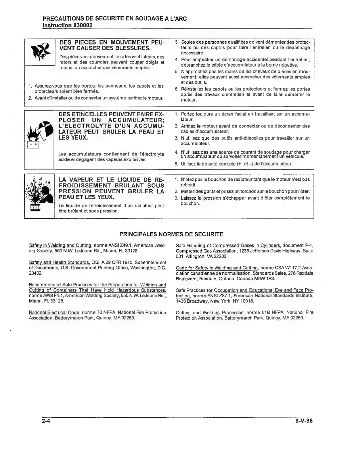
DES
PIECES
EN
MOUVEMENT
PEU-
VENT
CAUSER
DES
BLESSURES.
Des
pièces
en
mouvement,
tels
des
ventilateurs,
des
rotors
et
des
courroies
peuvent
couper
doigts
et
mains,
ou
accrocher
des
vêtements
amples.
1.
Assurez-vous
que
les
portes,
les
panneaux,
les
capots
et
les
protecteurs
soient
bien
fermés.
2.
Avant
d'installer
ou
de
connecter
un
système,
arrêtez
le
moteur.
DES
ETINCELLES
PEUVENT
FAIRE
EX-
PLOSER
UN
ACCUMULATEUR;
L'ELECTROLYTE
D'UN
ACCUMU-
LATEUR
PEUT
BRULER
LA
PEAU
ET
LES
YEUX.
Les
accumulateurs
contiennent
de
l'électrolyte
acide
et
dégagent
des
vapeurs
explosives.
LA
VAPEUR
ET
LE
LIQUIDE
DE
RE-
FROIDISSEMENT
BRULANT
SOUS
PRESSION
PEUVENT
BRULER
LA
PEAU
ET
LES
YEUX.
Le
liquide
de
refroidissement
d'un
radiateur
peut
étre
brülant
et
sous
pression.
.
Seules
des
personnes
qualifiées
doivent
démonter
des
protec-
teurs
ou
des
capots
pour
faire
l'entretien
ou
le
dépannage
nécessaire.
4.
Pour
empécher
un
démarrage
accidentel
pendant
l'entretien,
débranchez
le
cáble
d'accumulateur
à
la
borne
négative.
5.
N'approchez
pas
les
mains
ou
les
cheveux
de
pièces
en
mou-
vement;
elles
peuvent
aussi
accrocher
des
vétements
amples
et
des
outils.
6.
Réinstallez
les
capots
ou
les
protecteurs
et
fermez
les
portes
aprés
des
travaux
d'entretien
et
avant
de
faire
démarrer
le
moteur.
.
Portez
toujours
un
écran
facial
en
travaillant
sur
un
accumu-
lateur.
2.
Arrêtez
le
moteur
avant
de
connecter
ou
de
déconnecter
des
cábles
d'accumulateur.
3.
N'utilisez
que
des
outils
anti-étincelles
pour
travailler
sur
un
accumulateur.
4.
N'utilisez
pas
une
source
de
courant
de
soudag
un
accumulateur
ou
survolter
momentanémen
5.
Utilisez
la
polarité
correcte
(*
et
—)
de
l'accumulateur.
e
pour
charger
un
véhicule.
.
N'ôtez
pas
le
bouchon
de
radiateur
tant
que
le
moteur
n'est
pas
refroidi.
.
Mettez
des
gants
et
posez
un
torchon
sur
le
bouchon
pour
Гбіег,
.
Laissez
la
pression
s'échapper
avant
d'ôter
complètement
le
bouchon.
PRINCIPALES
NORMES
DE
SECURITE
Safety
in
Welding
and
Cutting,
norme
ANSI
749.1,
American
Weld-
ing
Society,
550
N.W.
LeJeune
Rd.,
Miami,
FL
33128.
Safety
and
Health
Standards,
OSHA
29
CFR
1910,
Superintendent
of
Documents,
U.S.
Government
Printing
Office,
Washington,
D.C.
20402.
Recommended
Safe
Practices
for
the
Preparation
for
Welding
and
Cutting
of
Containers
That
Have
Held
Hazardous
Substances,
norme
AWS
F4.1,
American
Welding
Society,
550
N.W.
LeJeune
Rd.,
Miami,
FL
33128.
National
Electrical
Code,
norme
70
NFPA,
National
Fire
Protection
Association,
Batterymarch
Park,
Quincy,
MA
02269.
24
Safe
Handling
of
Compressed
Gases
in
Cylinders,
document
P-1,
Compressed
Gas
Association,
1235
Jefferson
Davis
Highway,
Suite
501,
Arlington,
VA
22202.
Code
for
Safety
in
Welding
and
Cutting,
norme
CSA
W117.2
Asso-
ciation
canadienne
de
normalisation,
Standards
Sales,
276
Rexdale
Boulevard,
Rexdale,
Ontario,
Canada
M9W
1R3.
Safe
Practices
for
Occupation
and
Educational
Eye
and
Face
Pro-
tection,
norme
ANSI
Z87.1,
American
National
Standards
Institute,
1430
Broadway,
New
York,
NY
10018.
Cutting
and
Welding
Processes,
norme
51B
NFPA,
National
Fire
Protection
Association,
Batterymarch
Park,
Quincy,
MA
02269.
8-V-96

430429-427
DESCRIPTION
OF
EQUIPMENT
DESCRIPTION
OF
EQUIPMENT
Generator
The
Меда-Агс®
diesel
engine-driven
arc
welding
machine
is
a
self-contained
unit,
mounted
on
a
welded
steel
frame.
The
unit
is
covered
by
a
sheet
metal
canopy,
bolted
directly
to
the
frame.
The
control
panel
is
at
the
back
(generator)
end
of
the
unit.
The
generator
is
an
asynchronous
brushless
self-
excited
design.
The
rotor
assembly
is
supported
on
a
heavy
duty
shaft
by
a
single
bearing
at
the
rear
and
a
flexible
disc
coupling
at
the
engine
flywheel.
The
generator
is
a
self-excited
design
utilizing
AC
capacitors
permanently
connected
to
an
excitation
winding
on
the
stator.
The
welding
circuit
3-phase,
wye
connected,
rec-
tified
to
DC
power
by
the
output
rectifier,
and
stabi-
lized
by
the
stability
reactor.
The
auxiliary
power
current
provides
115-volt
and
230-volt
AC
power
to
the
receptacles
on
the
Control
Panel
for
operation
of
small
tools,
lights,
etc.
See
Tabulated
Data
for
rated
auxiliary
power
of
your
unit.
Engine
The
engine
used
in
this unit
is
a
Perkins
Industrial
3-152
diesel
engine.
It
is
directly
coupled
to
the
welding
generator
shaft
by
a
flexible
coupling.
Identification
The
welding
generator
unit
has
an
identification
plate
attached
to
the
control
panel
on
the
left-hand
side.
The
unit
is
identified
as
to
SPEC
number,
by
the
dash
(—)
number
which
follows
it.
The
engine
identification
number
is
stamped
on
right-hand
side
ofthe
cylinder
block.
When
ordering
spare
parts,
or
communicating
about
this
machine,
be
sure
to
specify
the
engine
serial
number,
engine
type,
unit
specification
and
serial
numbers.
Left-
and
right-hand
sides
of
the
unit
are
determined
when
facing
the
control
panel.
See
Supplementary
Mate-
rials
for
address
for
communicating
or
ordering
engine
parts.
Tabulated
Data
Generator:
Output,
Auxiliary
Power..
ЗКМА,
115/230V
AC
Output,
Welding
Generator
.........
12
kW
Amperes,
rated
................
300
Amps
Voltage,
rated
...................
40
Volts
Voltage,
open-circuit
.......
(max.)
75
Volts
Duty
Cycle,
rated
..................
100%
Current
Range
—
И
Low
Range
1510
200A
НЯ
High
Range
30
to
400
А
Operating
Speed
.........
See
Engine
Data
Engine:
Make
and
model
—
Sie
de
Detroit
Diesel/Perkins
3-152
Type.
ге
аа
Industrial
diesel
Displacement
.......
152
cu.
in.
(2.50
liters)
Brake
horsepower
....
38
BHP
@
1800
RPM
Oil
sump
capacity.
.....
7-1/2
quarts
(7
liters)
Cooling
system
capacity
—
За
аа
лань
see cto
9-1/2
quarts
(9
liters)
Fuel
tank
capacity
—
За
бані
17
gallons
(U.S.)
(64.4
liters)
Weight
(dry)
..........
463
pounds
(210
kg)
Normal
operating
RPM.
.........
1800
RPM
Dimensions
and
Weight:
(See
Figure
4-1)
Width
(doors
closed)
...
28
inches
(711
mm)
Width
(doors
open)....
77
inches
(1956
mm)
Length...........
61-1/2
inches
(1562
mm)
Height
(top
of
canopy)
—
era
nS
Ne
ta
РАНО
НЛО
41
inches
(1041
mm)
Height
(over
eye
in
top)
—
CT
ОКИ
46
inches
(1168
mm)
Weight
(shipping)
—
а
das
УА
approx.
1700
pounds
(765
kg)
August
24,
1998
3-1

430429-427
ОЕЗСКІРТІОМ
ОР
ЕОШРМЕМТ
Range
Selector
Switch
Voltrneter
(Optional)
Ammeter
(Optional)
Control
Box
Door
Fuel
Gauge
Contactor
Current
Control
Arc
Force
Ampere
Control
10
Arme
Circuit
Breakers
9 9
5
15
Volt
о,
Кесеріасів
2
250
Мон
Receptacle
Current
Control
Switch
Control
Remote
Switch
Control
Receptacie
Throttle
Igniti
Hour
gnition
Thermostart
Switch
Pushbutton
Ae er
Water
Meter
Ой
Pressure
1g
Temp.
ig
Gauge
А-467
Figure
3-1
Control
Panel
Supplementary
Materials
NOTE:
Switch
must
be
in
OFF
position
to
Acopy
ofthe
Perkins
Handbook
for
Diesel
Engines
is
included
with
each
welding
generator
unit.
Addi-
tional
copies
may
be
obtained
from
the
manufac-
turer.
Engine
Controls
and
Instruments
Ignition
Switch
—
The
diesel
engine
starting
motor
is
actuated
by
this
switch,
located
in
the
lower
left-hand
corner
of
the
control
panel.
Do
NOT
crank
the
engine
for
more
than
30
seconds
at
a
time,
as
this
may
cause
the
starting
motor
to
overheat.
Allow
motor
to
cool
before
attempting
to
start
the
engine
again.
Place
switch
in
START
position
to
start,
and
return
to
RUN
position
after
the
engine
has
started.
When
engine
is
shut
down,
place
switch
in
OFF
position.
avoid
lighting
the
Alternator
and
Oil
Pres-
sure
light.
Throttle
—
This
control
shuts
the
diesel
fuel
sup-
ply
off,
for
normal
shutdown
of
the
engine.
Pull
the
control
handle
OUT
all
the
way
for
engine
to
run
at
rated
RPM
(1800).
Push
the
handle
/N
against
the
panel
to
shut
engine
down.
Turn
contro!
handle
counterclockwise
to
loosen,
and
clockwise
to
lock
it
in
position.
Thermostart
Pushbutton
—
Place
the
starter
Switch
in
КИМ
position
and
hold
the
pushbutton
/N
for
15
to
20
seconds,
prior
to
placing
the
starter
switch
in
START
position.
Continue
to
hold
it
/N
until
engine
fires.
3-2
August
24,
1998

CAUTION:
Do
not
hold
the
pushbutton
ІМ
for
any
longer
period
of
time
than
the
20
seconds
(above).
|
engine
does
not
Start
first
time,
place
starter
switch
in
OFF
position,
then
repeat
above
proce-
dure.
Oil
Pressure
Light
—
Glows
(red)
when
oil
pressure
drops
to
3-5
psi
for
any
reason.
Alternator
Light
—
Glows
when
engine
alternator
circuit
is
not
charging
the
battery
at
sufficient
level.
Fuel
Gauge
—
Indicates
level
of
fuel
in
fuel
tank.
Hour
Meter
—
Indicates
run
time
on
engine.
Water
Temp.
Gauge
—
Indicates
coolant
tempera-
ture.
Generator
Controls
Range
Selector
Switch
—
This
toggle
switch
is
used
to
select
either
the
low
or
high
welding
range,
as
indicated
on
the
Current
Control.
Current
Control
—
The
welding
current
control
is
located
in
the
center
of
the
control
box
door
panel.
Turning
knob
clockwise
will
increase
welding
cur-
rent,
counterclockwise
will
decrease
current.
Voltmeter
(Optional)
—
Indicates
open-circuit
and
welding
arc
voltage,
when
supplied.
Ammeter
(Optional)
—
Indicates
welding
current
being
used
to
weld,
when
supplied.
Arc
Force
Ampere
Control
—
Varies
the
short-cir-
cuit
(welding
arc)
current
and
produces
an
increase
of
amperage
when
arc
length
is
shortened.
Turning
430429-427
DESCRIPTION
OF
EQUIPMENT
this
control
clockwise
increases
arc
force,
counter-
clockwise
decreases
arc
force.
See
Operation
chapter
for
details.
Welding
Terminals
—
(See
Figure
3-2)
—
The
two
welding
terminals
are
located
on
the
Welding
Output
Panel,
which
is
located
on
the
left-hand
side
of
the
unit
(facing
the
control
panel).
See
instructions
in
Initial
Preparation
for
Use
located
in
the
Installation
chapter.
Auxiliary
Power
Receptacle
—
Duplex
receptacles
located
on
the
Control
Panel
(see
Figure
3-1)
furnish
3-kVA,
115-volt
and
230-volt,
60-Hz
power.
NOTE:
The
output
voltage
will
drop
below
the
rated
volts
when
engine
is in
the
idling
mode.
Low
voltage
may
damage
electrical
equipment
connected
to
the
generator
through
this
receptacle.
Welding
Terminals
Figure
3-2
Weld
Output
Panel
August
24,
1998

430429-427
DESCRIPTION
OF
EQUIPMENT
VOLT-AMP
CURVES
MODEL
MA-4030D
(TYPICAL)
WELDING
VOLTS
(DC)
ARC
FORCE
SETIINGS
WELDING
AMPS
(DC)
Volt-Ampere
Curve
3-4
August
24,
1998

430429-427
INSTALLATION
INSTALLATION
General
Engine
Driven
Welder
Installation
The
frame
of
an
engine
driven
welder
is
intended
to
be
a
base
to
held
the
welder
components
to-
gether.
This
frame
is
not
intended
to
be
the
primary
structure
of
a
trailer
or
wagon.
This
welder
is
in-
tended
to
be
installed
on
a
rigid,
flat
surface.
This
surface
must
allow
the
weight
of
the
welder
to
be
distributed
емепіу
along
the
length
of
the
welder
frame.
Never
install
any
vibration
isolation
material
(shock
mounts,
etc.)
beneath
the
welder
frame.
This
could
defeat
the
engine/generator
shock
mounts
and
cause
abnormal
vibration
throughout
the
welder
and
produce
vibration
related
problems.
Before
choosing
an
installation
location,
make
note
of
where
the
service
items
are
located
on
the
welder
(oil
change/fill,
battery,
air
filter,
fuel
fill,
etc.)
Install
the
welder
for
best
access
to
the
important
service
items.
Allow
sufficient
room
for
cooling
air
intake
and
exhaust.
if
you
are
unsure
about
any
installation
consult
the
factory.
Trailer
Installation:
Do
not
use
the
frame
assem-
bly
of
this
welder
as
the
frame
of
a
trailer
(do
not
attach
axles
or
tongues
directly
to
this
frame).
Wnen
a
trailer
is
required,
use
only
trailers
with
its
own
support
frame
that
has
a
gross
weight
rated
to
carry
the
weight
of
the
welder
and
any
other
components
mounted
on
the
trailer.
Be
sure
the
trailer
tires
are
for
use
with
trailers.
The
soft
sidewall
design
used
in
radial
tires
can
cause
vibration
related
problems.
Be
sure
welder
frame
and
trailer
frame
are
electrically
bonded
together.
Truck
Bed
Installation:
When
installing
this
welder
on
the
bed
of
a
truck
allow
the
welder
to
sit
flat
on
the
bed,
or
a
surface
which
completely
con-
tacts
the
bottom
of
the
welder
frame.
Do
not
modify
the
welder
frame
by
cutting
or
otherwise
damaging
it
or
the
warranty
may
be
voided.
Bolt
the
welder
frame
directly
to
the
bed
to
secure
it.
Do
not
install
any
vibration
absorption
device
(shock
mounts,
etc)
between
the
welder
and
the
truck
bed.
Be
sure
welder
frame
and
truck
frame
are
electrically
bonded
together.
Ground
Installation:
The
welder
will
operate
per-
fectly
fine
just
sitting
on
the
ground,
with
or
without
August
24,
1998
the
shipping
skid.
No
special
precautions
are
re-
quired.
Location
For
best
operating
characteristics
and
longest
unit
life,
take
care
in
selecting
an
installation
site.
Avoid
locations
exposed
to
high
humidity,
dust,
high
am-
bient
temperature,
or
corrosive
fumes.
Moisture
can
condense
on
electrical
components,
causing
corro-
sion
or
shorting
of
circuits.
Dirt
on
components
helps
retain
this
moisture
and
also
increases
wear
on
moving
parts.
Safety
Refer
to
additional
installation
instructions
under
the
Safety
Warnings
chapter
included
in
this
man-
ual.
Indoor
Installation
Adequate
air
circulation
is
needed
at
all
times
in
order
to
assure
proper
operation.
Provide
at
least
24
inches
(610
mm)
of
space
at
radiator
end
of
unit.
Make
sure
that
ventilation
openings
are
not
ob-
structed.
Allow
ample
space
to
open
canopy
doors
on
sides
of
the
unit
(see
Tabulated
Data
in
Descrip-
tion
of
Equipment
chapter
for
dimensions)
for
serv-
icing,
and
space
at
the
control
panel
end
of
unit
for
Operation.
If
unit
is
to
be
operated
inside
a
building,
make
certain
there
is
adequate
ventilation
to
carry
off
escaping
exhaust
fumes
and
to
provide
an
ample
supply
of
oxygen.
Place
unit
so
that
exhaust
fumes
are
carried
out
of
the
building
using
the
shortest
exhaust
pipe
possi-
ble
and
one
with
the
fewest
possible
number
of
bends.
Exhaust
back
pressure
can
seriously
affect
engine
efficiency.
All
exhaust
connections
must
be
gastight.
Portable
Installation
For
portable
use,
the
machine
may
be
located
within
12
inches
(305
mm)
of
a
truck
cab,
panel,
or
whatever,
if
it
is
to
be
operated
in
the
open
air.
The
engine
ofthe
welding
machine
must
be
placed
at
the
tongue
end
of
the
portable
mounting
for
proper
balance.
If
leads,
etc.,
are
to
be
stored
on
ће
4-1

430429-427
INSTALLATION
unit,
they
must
be
forward
ої
the
axle
to
maintain
proper
balance
of
loading
on
the
tongue
end
of
the
unit.
NOTE:
The
unit
should
be
operated
in
as
near
a
normal
horizontal
position
as
possi-
ble
and
never
at
a
tilt
greater
than
10?
side-
ways
and/or
7?
maximum,
rear
down.
Initial
Preparation
For
Use
1.
Open
canopy
doors
on
sides
of
engine.
CAUTION:
The
canopy
doors
may
fall
to
a
closed
position
during
operation
of
the
unit
if
it
is
resting
on
an
inclined
surface,
or
for
other
reasons.
Tie
the
doors
to
each
other,
to
lifting
eye
or
fuel
filler
cap.
Failure
to
do
so
may
result
in
injury
to
operating
personnel.
2.
Inspect
unit
thoroughly
to
be
sure
it
is
in
proper
working
order.
Check
all
fuel
and
wire
connections
to
be
certain
they
are
secure.
Tighten
any
loose
screws,
nuts,
or
bolts.
Check
closely
for
any
dam-
age
which
may
have
occurred
in
transit.
3.
Remove
all
special
tags
from
the
machine,
read
carefully
and
follow
any
special
directions
they
may
carry.
Keep
tags
with
manual
for
future
reference.
4.
Make
certain
that
all
radiator
air
passages
and
cooling
fins
are
free
from
foreign
matter.
Use
clean,
dry
compressed
air
to
blow
dirt
and
dust
out
of
cooling
passages
and
control
cabinet,
25
psi
(172
kPa)
maximum
pressure.
5.
Attach
battery
cables
to
poles
of
battery
as
indicated
on
wiring
diagram.
The
negative
(—)
pole
should
be
grounded
to
the
frame
of
the
unit
in
a
secure
manner.
WARNING:
Connect
proper
bat-
tery
cable
clamp
to
the
positive
(*
)
battery
post
first,
then
the
other
cable
clamp
to
the
nega-
tive
(—)
post.
CAUTION:
A
short
circuit
to
rectifier
is
created
if
a
battery
is
installed
with
po-
larity
reversed.
Current
can
flow
from
positive
terminal
of
battery
through
negative
and
positive
rectifiers
and
into
heat
sink.
From
heat
sink
a
completed
circuit
exists
back
to
negative
battery
terminal.
Full
battery
voltage
will
be
im-
pressed
on
rectifiers,
in
the
alternator.
The
resulting
high
current
will
damage
rectifiers
and/or
wiring
harness.
6.
Fill
fuel
tank
with
grade
of
fuel
recommended
by
engine
manufacturer.
(Consult
engine
instruction
manual.)
Be
sure
fuel
is
free
of
WATER
and
other
foreign
matter.
Make
sure
air
vent
to
fuel
tank
is
open.
See
Safety
Warnings
chapter
included
in
this
manual
for
precautions
necessary
when
filling
the
tank.
7.
Check
to
be
sure
that
radiator
is
full
(about
1"
below
neck).
If
not,
add
enough
coolant
(50/50
mix
of
water
and
antifreeze)
to
fill.
8.
Pull
the
dipstick
and
check
the
oil
level
in
crank-
case.
If
it
is
necessary
to
add
oil,
fill
to
dipstick
mark
with
correct
seasonal
grade
of
quality
detergent
oil.
See
engine
operator's
manual
for
recommended
viscosity
and
temperature
chart
(unit
is
shipped
with
SAE
10W30
oil
installed).
9.
After
engine
has
been
properly
prepared
for
use,
start
the
engine,
and
allow
it
to
idle
for
30
minutes
or
so.
Carefully
check
again
for
any
leaks
or
loose
connections
during
this
period.
10.
Determine
which
welding
polarity
will
be
suit-
able
for
the
welding
job
to
be
done.
a.
For
STRAIGHT
polarity
(DCEN)
attach
ELEC-
TRODE
lead
(leading
to
electrode
holder)
to
the
NEGATIVE
(—)
terminal
on
the
Terminal
and
Recep-
tacle
Panel.
Attach
the
WORK
lead
(with
clamp
on
end)
to
POSITIVE
(*
)
terminal.
b.
For
REVERSE
polarity
(DCEP)
attach
ELEC-
TRODE
lead
(leading
to
electrode
holder)
to
the
POSITIVE
(*
)
terminal.
Attach
the
WORK
lead
(with
clamp
on
end)
to
the
NEGATIVE
(—)
terminal.
CAUTION:
Do
not
change
welding
leads
while
generator
is
running,
as
open-cir-
cuit
voltage
(80
volts)
is
furnished
to
the
terminals.
Shut
engine
down
to
change
leads.
11.
Make
sure
that
no
loose
bars,
tools,
parts,
etc.,
are
in
or
on
any
part
of
engine
as
they
could
cause
4-2
August
24,
1998
Table of contents
Other Thermadyne Portable Generator manuals

Popular Portable Generator manuals by other brands


Scheppach
Scheppach SG1600i Translation of original instruction manual

Generac Power Systems
Generac Power Systems G0059395 owner's manual

Porter-Cable
Porter-Cable T525 instruction manual

Surtek
Surtek GG525 User manual and warranty

Tektronix
Tektronix TSG-271 instruction manual

GENTRON
GENTRON GG3500P owner's manual


