Thermal Gas Systems HALOGUARD IR User manual

Rev.1/26/01 1
HALOGUARDTM IR
MULTI-POINT, COMPOUND SPECIFIC MONITOR
INSTRUCTION MANUAL
SERIAL NO.
MODEL NO.
Temp. Range
1 - = > 60oF
2 - = 40 - 60oF
3 - = < 40oF
Gas Type
1 - R-11
2 - R-12 Range
3 - R-22 1-0-1000ppm
4 - R-134a
5 - R-113
6 - NH3
7 - R-123
Outputs
1 - 4 x 5A Relays
2 - 0 – 5/10 VDC
3 - 4 - 20mA
4 - RS232/485
5 – 7 x 10A.
Options/Accessories
A - Audible Alarm
B – Battery B/U-UPS
E - Inlet/Outlet Extension
L - Strobe Light
S - Scanner
R – Remote Expansion
Module
11285 Elkins Road Bldg. H-1
Roswell, GA 30076
TEL: 770-667-3865
FAX: 770-667-3857
www.thermalgas.com

Rev.1/26/01 2
IMPORTANT
READ ENTIRE BOOKLET BEFORE
INSTALLING OR OPERATING
HALOGUARDTM IR MONITOR
TABLE OF CONTENTS
Page
1. Unpacking Instructions ------------------------------------------------------------ 3
2. Before Installation------------------------------------------------------------------ 3
3. Function of LED’s, Pushbuttons, & LCD Information------------------------ 4
4. Installation--------------------------------------------------------------------------- 6
5. Set-up & System Configuration --------------------------------------------------8
6. Calibration, Testing, & Trouble Shooting -------------------------------------- 10
7. Maintenance & Specifications---------------------------------------------------- 11
FIGURES Page
1. Typical Area Monitoring Installation ----------------------------------------- 3
2. Mounting Dimensions ------------------------------------------------------------ 4
3. LCD Display Information -------------------------------------------------------- 4
4. Haloguard IR----------------------------------------------------------------------- 5
5. Analog Jumper Settings ---------------------------------------------------------- 6
6. Circuit Board----------------------------------------------------------------------- 7
7. Setup & Configuration Jumper Settings---------------------------------------- 8
8. Remote Expansion Module Terminations-------------------------------------- 9
9. Remote Expansion Module Circuit Board ------------------------------------- 9
10. Replacement Parts----------------------------------------------------------------- 11
11. Accessories------------------------------------------------------------------------- 11
12. Initial Factory Settings------------------------------------------------------------ 11
13. Refrigerant Exposure limits------------------------------------------------------ 11
Rev.1/26/01 3
UNPACKING INSTRUCTIONS
HaloguardTM monitors are carefully packed, inspected and delivered to the carrier in good condition. If
damage occurs in transit it is the responsibility of the carrier. Carefully inspect the unit upon receipt.
Any damage should be reported to the carrier and an inspection requested. After inspection by the
carrier and your receipt of his acknowledgment as to the damage, contact us for return authorization
(RMA). We cannot file claims for damaged goods on your behalf, but we will assist you in any way we
can. In order to expedite our work, please provide serial number and model number when you call.
WE CANNOT ACCEPT RETURNS WITHOUT PRIOR APPROVAL.
BEFORE INSTALLATION
1. Remove HaloguardIR from carton. Check contents against packing list. If shipment is incomplete,
contact us immediately.
2. Select a site for the installation:
a. Power requirements: Provide a clean source of power 115-230 VAC, 50/60 Hz, single phase 15A
minimum.
b. Sample tube pick-up should be located near potential leaks in a quiet area or downstream from
leak source in area with air movement.
c. Sample tube pick-up should be located 18” - 24” above the floor. If using optional scanner, locate
sample tubes at points near all chiller locations. Make sure each sample tube is equipped with an
end of line filter.
d. Make sure the area selected is not subject to flooding, potential impact or severe ambient
temperature and humidity changes (i.e. boiler blow-down or near roll-up doors).
e. Narrow band infrared detector is highly selective but may respond to the presence of other
refrigerants if interfering gas reaches a very high concentration. For accurate leak detection
select a location free from interfering vapors. Contact us for specific gas interference.
3. The Haloguard IR should be installed indoors, about five feet above the floor and at a location easily
visible to operators, in an area with minimal vibration, and with temperature and humidity changes
like sample pick-up location. DO NOT MOUNT DIRECTLY TO CHILLER
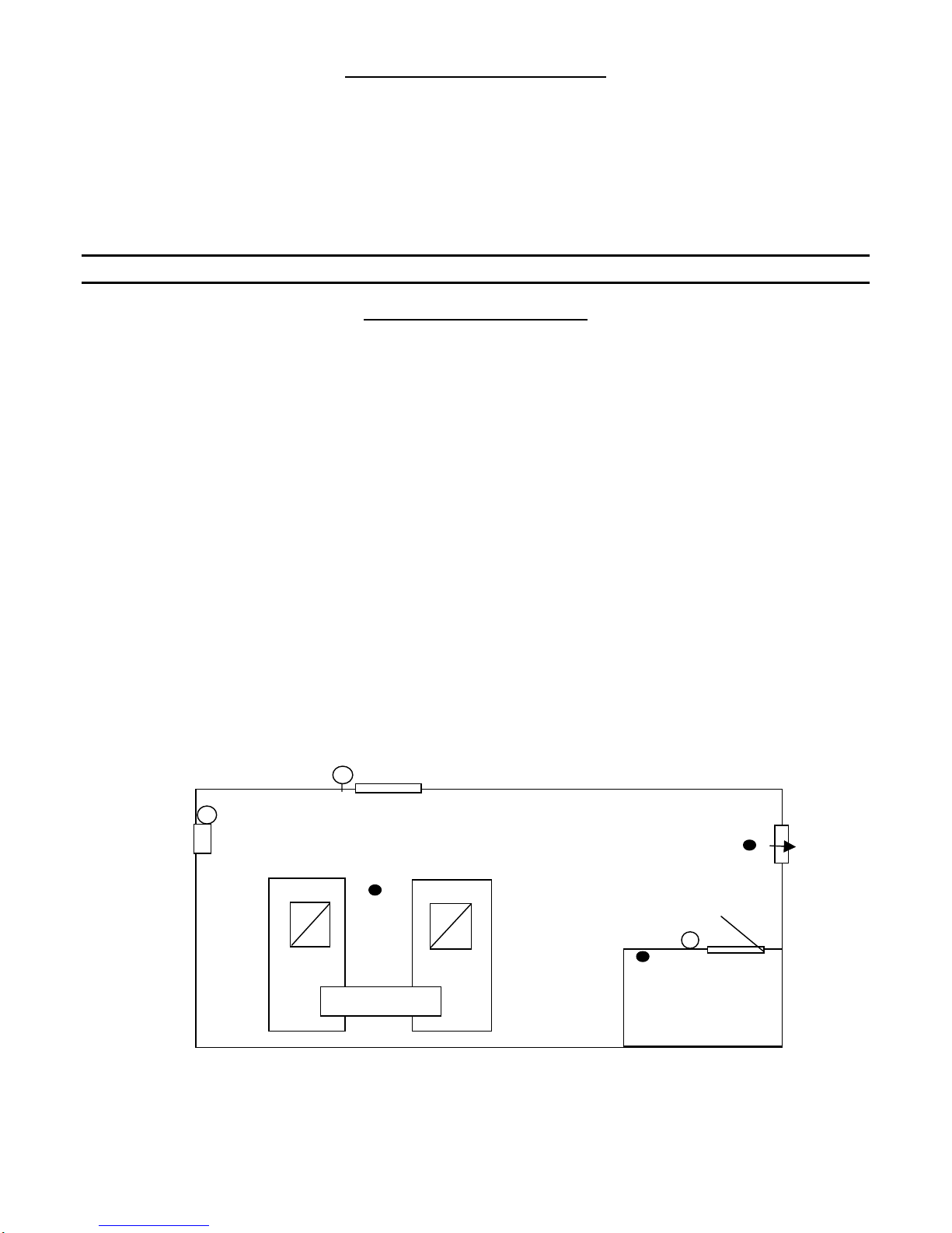
Fig. 1-Typical Area Monitoring Installation
Remote Alar
m
Refrigerant
Storage Area
Sam
p
le
p
oin
t
Sam
p
le
p
oin
t
Sam
p
le
p
oin
t
Haloguard
Panel and
Local Alarm Fan
Chillers
Remote Alarm

Rev.1/26/01 4
IMPORTANT
CONSULT LOCAL AND NATIONAL ELECTRICAL CODES FOR ANY SPECIAL
REQUIREMENTS OR RESTRICTIONS BEFORE INSTALLING HALOGUARD
FUNCTION OF LED’S, PUSHBUTTONS, and LCD DISPLAY INFORMATION
1. READY LED-Steady LED means Haloguard IRis measuring ppm; blinking indicates otherwise
2. POWER LED- Green LED indicates Haloguard IRis receiving power.
3. FAULT LED – LED indicates malfunction. LCD indicates specific type of failure (See Figure 3)
4. ALARM 1, ALARM 2, ALARM 3 LED’s-Adjustable Alarm levels & relays - Factory set for
particular refrigerant (See Figure 12 ). User adjustable as follows:
RANGE 1 PPM
INCREMENTS 10 PPM
INCREMENTS
0 - 1000 ppm 10 - 100 100 - 1000
5. MANUAL SCAN push-button
6. RESET/SILENCE push-button - Silences alarms, disables relays, and resets instrument for 20
minutes. LCD displays RESET/SILENCE with 20 minute countdown. Alarms are automatically
reactivated if alarm condition is not corrected. Reset is automatically initiated on start-up and
after power failure.
7. Optional Display Features: TWA Integration – Haloguard IRcalculates an 8 hr. Time Weighted
Average (TLV-TWA),displays this value on LCD, activates Alarm 1 LED and relay if factory
set PPM value is exceeded. Used for gases with TLV-TWA less than 1000ppm. TLV-TWA
Alarm is factory set and not user adjustable.
14 3/4”
11”
Fig. 2- Mounting Dimensions
Channels 1 - 24 (Opt. Scanner Only)
Alarms
- Alarm 1
- Alarm 2
- Alarm 3
- Reset
- Fault
- Silenced
Set-up Messages
-Set Channel (1-24)
-Set Gas Type (R11,12,22,123,134)
-Test Alarm 123456 Fault
-Set Alarm 123456 Latch On/Off
Calibration Messages
-Zero Calibrate, connect scrubber,
follow on screen directions
-Span Calibrate, insert key from gas cal kit
Fault Messages
- Chopper Failure
- Discontinuity
- Lamp Failure
- Scan Discont
- Temperature
- Pressure
- Scanner Stop
Gas Type (R-11, R-12, R-22, R-123, R-134, etc.)
Figure 3 - LCD Display Features
8 hr. TWA
pp
m
(
R-123
)
Concentration
(
p
pm)

Rev.1/26/01 5
Sample Inlet
1 inlet Std.
2,4,8 inlet Opt
Inlet can be
extended 300’
using 0.125”
tubing. All lines
must have end
of line filter.
Mounting Holes
(
4
)
0.25”dia.
Remote
Reset In
Analog/ Digital Output
4-20mA, 0-5VDC
RS 232/485 serial O
p
t.
Relay/Binary Output
4x5A. dry contact Std
7x10A. dr
y
contact O
p
t.
Power In
120/230Vac
50/60Hz
Reset/Silence
Pushbutto
n
Test
Pushbutto
n
Sample
Outlet
Enclosure is 12” x 14” x 4.5”; NEMA 250 rated
LCD
Local Strobe Alarm-Opt.
Local Audible alarm-Opt.
Ready
Power
Fault
Alarm 3
Alarm 2
Alarm 1
Aux. Inputs and Remote Expansion
Module In
Fig. 4-Haloguard IR

Rev.1/26/01 6
INSTALLATION
1. Check power supply and determine best location. (See Section “Before Installation”)
2. Disconnect power before beginning.
Refer to figures 2, 3, 4, 5 and 6 before proceeding.
3. Installation
a. Mounting HaloguardIR
1. Securely mount the unit to a wall or support using the (4) mounting holes.
2. Remove cover.
3. Install sample tube to 18-24” above floor, install end of line filter. Sample inlet may be
extended up to 300FT with 0.125” OD x 0.093” ID nylon, copper or stainless steel tubing.
When extending sample tubing:
a. Keep sample lines as short as possible and free of kinks.
b. Exhaust to atmosphere. DO NOT install any device which might restrict the flow.
4. Route sample inlet tubing through entry indicated ( Figure 4 ) and insert into one-touch
fitting provided. To remove tubing pull plastic ring on end of one-touch fitting to release.
b. Wiring Connections:
1. Relay Terminals – Route wire through entry indicated. (Figure 4 ). Remove safety cover.
Connect alarm relays NO or NC (Figure 6) required.
2. Power Supply Wiring-Route wire through entry indicated. (Figure 4 ). Remove safety cover.
All connections are made to the terminal block labeled IN 120/250VAC (Figure 6). Connect
HOT AC wire to Terminal L. Connect NEUTRAL wire to terminal N. Connect a GROUND
wire to terminal G. Auxiliary 120/250VAC output is provided to activate remote audible and
strobe light alarms. This output is not fused. Limit load to 0.5A.max total.
**WARNING** analog output is a driven signal, do not connect any wire with voltage or
current to analog output terminals
3. Analog Output (Optional) – Two analog outputs are provided for connection to remote
recording devices (Figure 6); PPM analog output is for gas concentration; Channel analog
output is for channel location. Connect 18 ga. twisted shielded pair as follows, maximum
length 300 ft.:
Analog Output Range Terminal Position
0-10VDC V and GND
4 - 20mA I and GND
Figure 5 - Analog Jumper Settings
4. Auxiliary Input(VDC) – Five analog inputs (EXT INPUT 3-8) are provided for connection
of remote input devices such as oxygen sensors, CO sensors, and flammables sensors
(Figure 6)
5. Auxiliary Input(mA) – Two analog inputs (Remote IR 1&2) are provided for connection of
remote input devices such as Haloguard Remote Expansion Module (Figure 6)

Rev.1/26/01 7
6. Uninterruptable Power Supply (Optional) – Make sure UPS is fully charged. Plug UPS into
power supply, turn switch ON. Connect HaloguardIR to UPS, with power cord provided
c. On power-up, RESET and 20 minute count down will appear on LCD. For 20 minutes after
power up all alarms and relays are automatically disabled. Whenever power is disrupted,
RESET mode will be automatic (unless optional UPS is supplied) to protect against false alarms.
Allow 1 hour for warm-up from cold start.
Figure 6 Circuit Board
Rev.1/26/01 8
SETUP and SYSTEM CONFIGURATION
Locate configuration jumpers on Figure 6. Select configuration settings from the following:
JP FUNCTION
RUN Select run for normal operation
SETUP Set gas type and number of active channels
TEST Sequentially activates all alarm & Fault LED’s &
relays
ALARM Set Point Adjustment for Alarm 1, 2, and 3
CAL Zero Calibration
SPAN For use only with span gas and key
JP5 Factory only
Figure 7 – Setup & Configuration Jumper Settings
1. RUN - Remove jumper to initiate other modes. Replace jumper when finished.
2. SETUP - Gas type will be pre-set at the factory. Number of active channels will be the
maximum possible for the instrument as supplied (Fig.12). To change gas type or number of
active channels use jumper to initiate the set-up mode. Select channel with cursor by using
the UP/DOWN/ENTER pushbuttons. Select gas type for each channel by using UP/DOWN
pushbuttons. “NONE” selected in the gas type menu will skip channel
3. TEST-Select test mode. Select alarm with cursor by using UP/DOWN/ENTER pushbuttons
4. ALARM - Alarm levels will be pre-set at the factory (Fig.12). To change select ALARM
with cursor using UP/DOWN/ENTER pushbuttons. Change PPM using UP/DOWN/ENTER
pushbuttons. OFF selected turns alarm off.
5. CAL – Install optional activated charcoal filter in channel 1, follow on screen directions to
zero calibrate using ENTER pushbutton.
6. SPAN –Key and instructions for use are included with Span Gas Calibration Kit
7. JP5- Factory only.
System Configuration:
1. Relay Setup - Factory recommended setting is unlatched mode; e.g., the alarm LED’s and
relays will return to a normal status when gas concentration goes below alarm setpoint. To
select latched mode place jumper on ALARM setting. Select LATCH mode with the cursor
using UP/DOWN/ENTER pushbuttons. LATCH ON appears on the LCD Display. Latched
mode requires manual RESET of all alarms
2. Analog Output (optional) is factory set at 0 - 5 VDC or 4 - 20mA as ordered. Use Analog
trim pot (Figure 6) to adjust for up to 0-10VDC range
3.LCD display adjustment potentiometer changes brightness. (Figure 6).
4. Two, Four or Eight Point Scanner - (Optional) Scanner is factory installed. Scanner
automatically sequences through each port (1-2, 1-4 or 1-8).
a. Manual Scan - While in RUN Mode,
1. Press MAN SCAN button on side of controller. Each time the button is pressed,
display will advance to next sample point. Controller will return to automatic
sequencing within 2 minutes.
2. Adjust Scan Rate.-Rate is factory set at 4 seconds per point. Rate is adjustable from
3-10 seconds. To change scan display rate press ENTER from RUN mode; adjust
UP/DOWN; press ENTER to return to RUN mode
Rev.1/26/01 9
5. Installation of Optional Remote IR Expansion Module
Refer to FIGURE 4, 6, 8, and 9 before proceeding.
DO NOT CUT SUPPLIED CABLE
Controller is provided with 18” cable with DIN connector and expansion module is provided
with 6-1/2’ cable. If cable extension is required we recommend 3 conductor 18 ga. cable with
foil shield, Carol C2535 or equal. Use 3/4” conduit if required. Maximum 1000 ft. length
Remove 18” cable with DIN connector from controller circuit board. Splice or solder extension
cable to end of 18” cable. Reconnect extended sensor cable to terminal block on circuit board of
controller.
Terminal Provided
Wire Color Extension
Wire Color Function
CHA Red Red Scanner
SIG White White Signal
GND Blk/Blk Black Ground
Note - CHA Terminal is used for expansion modules with scanner only.
Figure 8 – Remote Expansion Module Terminal Connection
To avoid nuisance alarms remove alarm jumper “AUD” before beginning.
To compensate for line losses adjust signal voltage with a digital VOM as follows:
1. Open cover on Remote IR expansion module. Move jumper from RUN to SETUP. Wait
approximately 1 minute before proceeding .
2. Open cover on HaloguardController .
3. With VOM on 5 VDC scale, place VOM probe on SIG (+) and GND (-) Test points on
Controller (see Figure 6).
Adjust potentiometer on Controller Circuit Board, with screwdriver until it reads 4.975
+/-0.025 VDC.
Display will show FAULT if out of range and SETUP, if trimmed to 4.975+/-0.025 VDC.
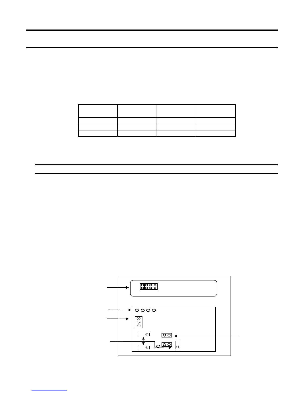
4. If Remote expansion module is provided with scanner it will be necessary to lock the scanner
on channel 1 using the jumper provided (Figure 9).
5. When done, replace expansion module jumper in RUN mode. Replace AUD jumper to
activate alarms circuit.
Connector for Digital Calibrator
(
O
p
tional
)
1
8
Lower Circuit
Board
IR Module Run/
Setup Jumper
R
un
Setup
DO NOT ADJUST POTS
Fi
g
ure 9 - Ex
p
ansion Module Circuit Board
Cable to Controller
(DO NOT REMOVE) White
Black
Red
Scanner Circuit Board

Rev.1/26/01 10
CALIBRATION
Haloguard IR monitors are factory calibrated to the specific gas of interest. Field calibration is not
required for operation in typical machine room environments during the first twelve months of operation
unless a change in gas type is required.
For those who wish to check the factory calibration or change the gas type an optional Span Gas Kit is
available. Instructions for use are included with kit
TESTING
The Haloguard IRTM should be tested at start-up, after any changes to alarm protocol, and after each
alarm level condition has been corrected. During testing, display will indicate TEST MODE
a. Alarm Test –Enter TEST mode with jumper, select alarm with cursor by using
UP/DOWN/ENTER pushbuttons. Check all alarms sequentially. Alarm relays, lights, audible
and remote alarms (if equipped) will activate if selected.
b. Reset Test - Push RESET/SILENCE button; alarm relays, audible and remote alarms (if
equipped) will become inactive for 20 minutes. Display will read RESET and indicate minutes
to completion of reset period.
TROUBLESHOOTING
The most frequent cause of nuisance alarms and fault is improper set-up, primarily due to:
a. Failure to install in accordance with instructions.
b. Not allowing sufficient warm-up time.
c. Poor sensor location.
To check Zero Calibration, fill a clean plastic trash bag with clean outside air, tie off with twist-tie, let
sample stabilize inside for 15 - 20 minutes. Insert sample tube into bag . For models equipped with
scanner allow up to 2.5 minutes per channel for clean air sample analysis
.
Observe LCD response, if displayed PPM value drops lower then Haloguard IR is detecting the presence
of the gas of interest or another gas which absorbs infrared light at the same frequency.
Remove sample tube from bag and observe LCD response. If displayed PPM value moves higher, look
for refrigerant leaks or possible sources of interfering gases (See “Before Installation). and relocate
sample point.. Keep in mind that the Haloguard IR is much more sensitive than hand held leak detectors,
it may detect a leak when hand held units show no response
We wish to aid with any problems you might experience with the Haloguard IR. When contacting
Thermal Gas Systems, Inc. Service Department, please have the following information ready
1. Model Number and Serial Number.
2. Description of the problem.
3. Remove cover. Place jumper on Alarm setting function and record settings. Place jumper on
Setup function and record settings
4. Advise the condition of all LED’s and the information displayed on the LCD.

Rev.1/26/01 11
MAINTENANCE
There is no scheduled maintenance for the first 12 months operation; after 12 months the internal and
external filters should be changed and the instrument should be gas tested in accordance with the
instructions. Self-diagnostics will indicate the cause of any unusual malfunction. To obtain spare or
replacement parts please contact Thermal Gas Systems, Inc.
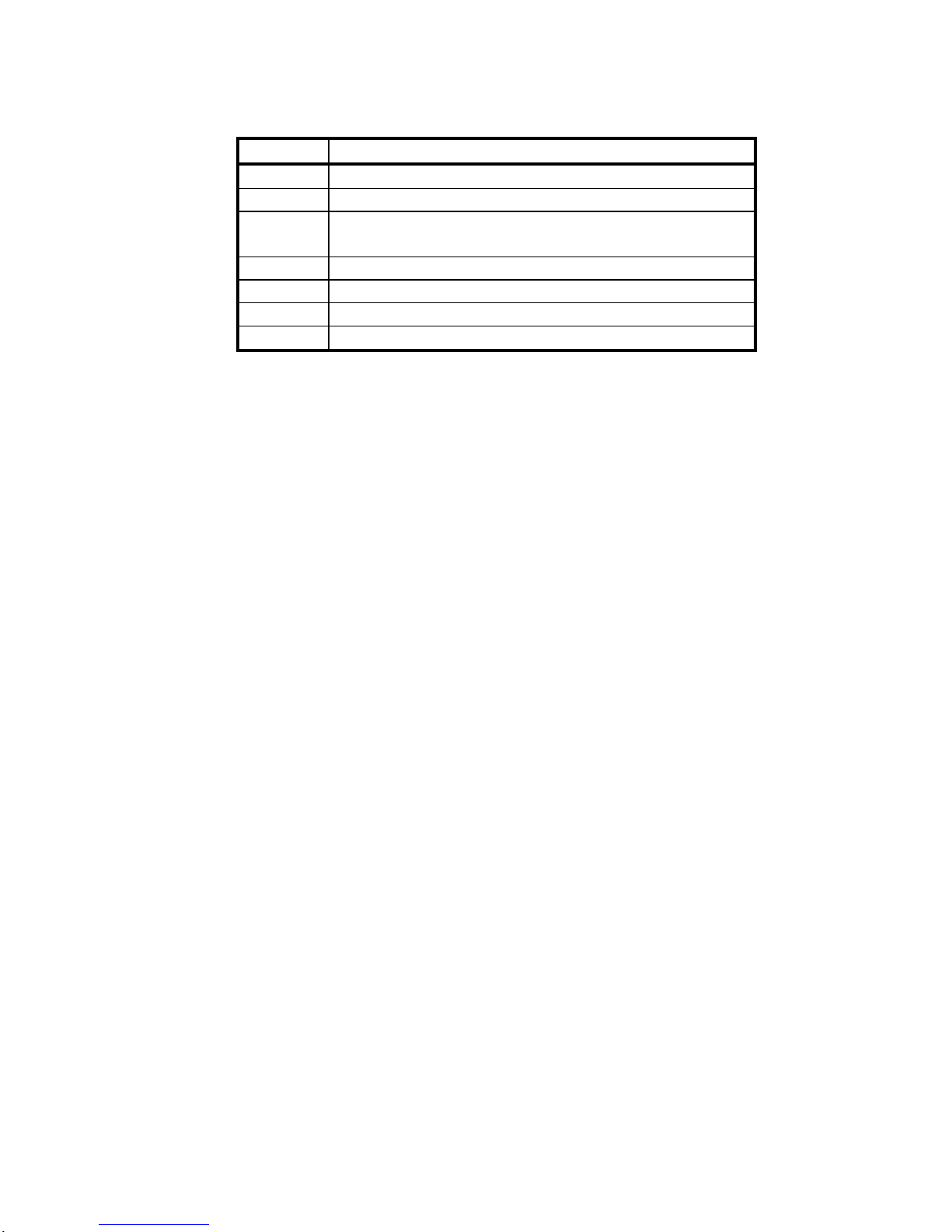
Description Part No.
Internal Filter, element A702
External Filter, element A703
Switcher Valve A501
Pressure Switch A708
Scanner, 2-station A501
Scanner, 4-station A502
Scanner, 8-station A503
Power Supply; 120/230VAC A707
Pump A709
Figure 10 – Replacement Parts
Description Part No.
Audible alarm, local A603
Strobe alarm, local A607
Audible alarm, remote A605
Strobe alarm, remote A606
Combination audible/strobe alarm, A604
Zero Gas Scrubber
Gas Calibration Kit A204
Fig. 11- Accessories
SPECIFICATIONS
Technology: Narrow band Photoacoustic Infrared
Electrical Supply: 115-230 VAC, 50-60Hz
Output Signal: Std. 4x3A Dry Contact SPDT
Opt. 7x10A. Dry Contact SPDT
Analog Output Opt. 0 – 5VDC or 4 - 20mA
Opt. RS232/485
Alarm Outputs: Three Level Contact Closure
Opt. Seven Level Contact Closure
Readout: Digital LCD, Displays Channel, PPM
Gas Type, and Fault Diagnostics
Display accuracy: 1ppm 10 - 100 ppm Range
10ppm 100 - 1000 ppm Range
Ranges: 10 - 1000 ppm R-11, 12, 22, R-123, -134a,
Operating Conditions:
+40oF to +120oF Non-condensing
Fault Diagnostics: Indicator Light and LCD Readout
(See Figure 5)
Enclosure: NEMA 250, NEMA4/12 optional
Weight: 20 lbs.
Dimensions: 12” W x 14” H x 4.5” D
Sample Rate 1.5Liter/min.
Response Time: < 1 Minute single point
< 2.5 Minutes per point with optional
scanner.
Initial factory settings are:
Function Setting
Channel
1 2 3 4 5 6 7 8
Gas
Alarm 1
Alarm 2
Alarm 3
Figure 12 - Initial Factory Settings
GAS TLV-
TWA* CEIL PEL
R-11 •1000 •
R-12 1000 •1000
R-22 1000 •1000
R-123 50 ••
R-134a 1000 •1000
•
••
Figure 13- Refrigerant Exposure limits
Table of contents
Other Thermal Gas Systems Monitor manuals


