Thermal Gas Systems HALOGUARD Series User manual

1 Rev.2 1/26/98
HALOGUARD
TM
IR MONITOR
(OPTIONAL) FOUR or EIGHT POINT SCANNER
INSTRUCTION MANUAL
S E R IA L N O .
M O D E L N O .
T em p . R a ng e
1 - = > 60oF
2 - = 4 0 - 6 0oF
3 - = < 40oF
G a s T ype
1 - R -1 1
2 - R -1 2
3 - R -2 2
4 - R -1 3 4a
5 -
6 -
7 - R -1 2 3
R an ge
1 - 0 - 100 0 pp m
M ou n t
1 - W all
O utp u ts
11 - 4 x 3 A R elays
12 - 0 - 5 V D C or
0 - 1 0 V D C
13 - 4 - 2 0m A
O p tion s/A ccessorie s
A - Au dib le A larm
B - U P S
E - In le t/ O utle t E xt en sion
L - Strob e Ligh t
S - S can n er
T - T W A In te gration
11285 Elkins Road Bldg. H-1
Roswell, GA 30076
TEL: 770-667-3865
FAX: 770-667-3857
www.thermalgas.com

2 Rev.2 1/26/98
IMPORTANT
READ ENTIRE BOOKLET BEFORE
INSTALLING OR OPERATING
HALOGUARD
TM
IR MONITOR AND (OPTIONAL) SCANNER
TABLE OF CONTENTS
Page
1. Unpacking Instructions 3
2. Before Installation 3
3. Installation 7
4. Calibration 10
5. Testing 10
6. Trouble Shooting 10
7. Specifications 11
FIGURES
Page
1. Dimension Drawing 4
2. Controller Upper Circuit Board 5
3. Controller Lower Circuit Board 5
4. Controller LCD Display Features 6
5. Infrared (IR) Module Circuit Boards 6
6. Sensor Cable Terminal Connection 9
7. Analog Output Jumper and Terminal Settings 7
8. Function Jumper Settings 8
9. Initial Factory Settings 11
10. Exposure Limits 11
11. Wiring Diagram 12

3 Rev.2 1/26/98
UNPACKING INSTRUCTIONS
Haloguard
TM
monitors are carefully packed, inspected and delivered to the carrier in good condition.
If damage occurs in transit it is the responsibility of the carrier.
Carefully inspect the unit upon receipt. Any damage should be reported to the carrier and an
inspection requested. After inspection by the carrier and your receipt of his acknowledgment as to
the damage, contact us for return authorization (RMA). We cannot file claims for damaged goods
on your behalf, but we will assist you in any way we can.
In order to expedite our work, please provide serial number and purchase date when you call.
WE CANNOT ACCEPT RETURNS WITHOUT PRIOR APPROVAL.
BEFORE INSTALLATION
1. Remove Haloguard
Controller and IR Sensor Module from carton. Check contents against
packing list. If shipment is incomplete, contact us immediately.
2. The following tools and hardware are required for installation and calibration.
a. Two standard & one philips screwdrivers; 1 - medium standard w/ long shaft, 1 - jewelers
fine standard & 1 - medium philips.
b. Needle-nosed electrician’s pliers
c. (8) No. 8 x 1” Screw (minimum)
d. Digital VOM
3. Select a site for the installation:
a. Power requirements: Provide a clean source of 115-230 VAC, 50/60 Hz, single phase circuit
rated 15A minimum Haloguard
Controller and IR Sensor Module.
b. Infrared (IR) Sensor Module should be mounted near potential leaks in a quiet area or
downstream from leak source in area with air movement.
c. Infrared (IR) Sensor Module sample tube end should be located 18” - 24” above the floor . If
using optional scanner, locate IR Module at a point central to chiller locations. Install inlet
extension tube out to each remote sample location (up to 200 Ft. from IR module). Make sure
each sample tube is equipped with an end of line filter.
d. Make sure the area selected is not subject to flooding, potential impact or severe ambient
temperature and humidity changes (i.e. boiler blow-down or near roll-up doors).
e. Infrared detector is highly selective but may respond to the presence of other gases (i.e. paint
thinner, cleaning fluids and other refrigerants) if interfering gas reaches a high concentration.
For accurate refrigerant leak detection select a location free from above fumes or temporarily
disable sensor when they are present. Contact TGS for specific interference’s.
4. The wall mounted controller should be installed indoors, approximately five feet above the floor
or at a location easily visible to operators, in an area with minimal vibration, and with
temperature and humidity changes like sensor location.
IMPORTANT
CONSULT LOCAL AND NATIONAL ELECTRICAL CODES FOR ANY SPECIAL
REQUIREMENTS OR RESTRICTIONS BEFORE INSTALLING HALOGUARD
.

4 Rev.2 1/26/98
5. LED Indicators, Pushbuttons, LCD Displays, and Relays
a. POWER LED- Green LED indicates Haloguard
is receiving AC power.
b. FAULT LED and Relay - Indicates malfunction. LCD indicates specific type of failure (See
Figure 4).
c. TEST Push-button - Energizes Alarm LED’s & relays. Depress button five (5) times to
sequence through each alarm level.
d. Adjustable Alarm LEDs & Relays -Indicate Alarm 1&Alarm 2 - Factory set for particular
refrigerant (See Figure 9). User adjustable as follows:
RANGE
1 PPM
INCREMENTS
10 PPM
INCREMENTS
0 - 1000 ppm 10 - 100 100 - 1000
Note: Optional TWA Integration activates Alarm 1 LED and relay when installed.
TLV-TWA Alarm is factory set and not user adjustable.
e. OFFSCALE LED and Relay - Factory set at 1000ppm
f. RESET Push-button - Silences alarm, disables relays, and resets instrument for 20 minutes.
LCD displays *CAUTION* and RESET with 20 minute countdown. Alarms are
automatically reactivated if alarm condition is not corrected. Reset is automatically initiated
on start-up and after power failure (Except when optional UPS is provided.).
6. Optional Features:
. TWA Integration - Haloguard
calculates an 8 hr. Time Weighted Average (TLV-TWA),
displays this value on LCD, activates Alarm 1 LED and relay if factory set PPM value is
exceeded. Only used for gases with TLV-TWA less than 1000ppm.
HALOGUARD
IR
CONTROLLER
5 1/2”
Figure 1 - Dimensional Drawing
4”
9”
3/4”
HALOGUARD
IR
MODULE
6 1/2”
14 1/4”
(By 4” Deep)
5 Rev.2 1/26/98
LCD Brightness
Adjustment
1 2 3
4 5 6
10 11 12
7 8 9
ALARM 1
FAULT OFFSCALE
ALARM 2
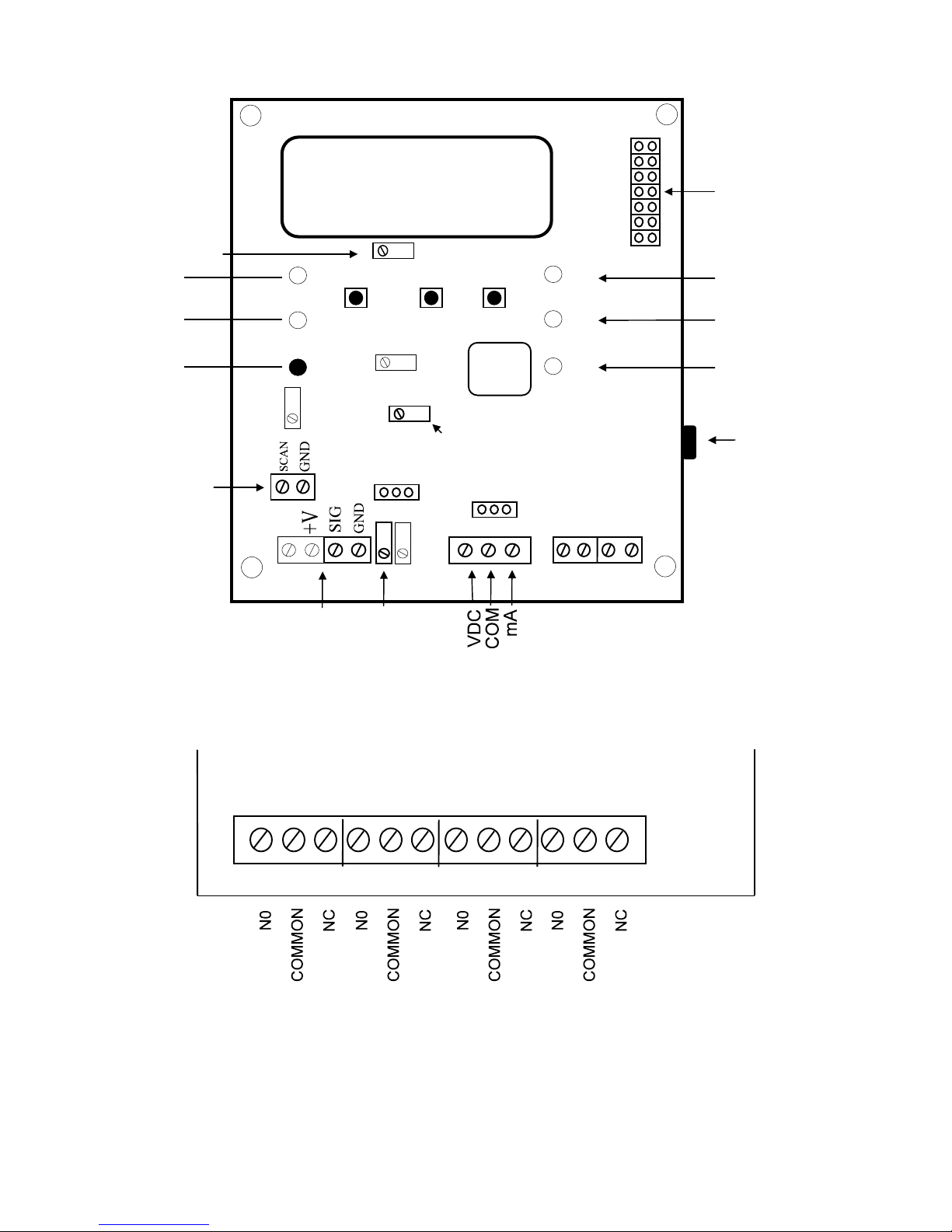
Figure 3 - Controller Lower Circuit Board
RUN
GAS
ALARM
ZERO
SPAN
AUD
J5
ANALOG
VOLT
mA
I
C
Offscale LED
Alarm 2 LED
Alarm 1 LED
Power LED
Fault LED
Test Button
IR
Trim
Analog Trim Pot
0
-
5 or 0
-
10 VDC
UP
ENTER
DOWN
Sensor
Connection
RS-232
Reset Button
Figure 2 - Controller Upper Circuit Board
Setup Jumpers
Processor
Chip
Scanner
Connection

Rev.1/26/98 6
Alarms
- Alarm 1
- Alarm 2
- Fault
- Latch ON
- OFF Scale
- Reset
Set up Messages
GAS - SET GAS TYPE
ALARM - SET ALARM 1 (ppm)
SET ALARM 2 (ppm)
SET SCAN RATE (scanner only)
Fault Messages
- Caution
- Chopper Failure
- Discontinuity
- Lamp Failure
- Scan Discontinuity
- Low Temp
- Pump Failure
- Scan Stop
-
Gas Type (R-11, R-12, R-123, R-134, etc.)
Figure 4 - Controller LCD Display Features
8 hr. TWA Concentration
(R-123)
Concentration
(ppm)
Channels 1 - 8 (Optional Scanner Only)
Flashing cursor means Auto Scan Mode (Opt. Scanner Only)
1
.
.
8
Lower Circuit Board
IR Module Run/
Setup Jumper
Run
Setup
DO NOT
ADJUST
POTS
Figure 5 - IR Module Circuit Boards
Cable to Controller
(DO NOT REMOVE)
White
Black
Red
Connector for Digital
Calibrator (Optional)
Scanner Circuit Board
(Optional)
Rev.1/26/98 7
INSTALLATION
1. Check power supply. (See Section “Before Installation 3a”)
2. Disconnect power before beginning.
3. Installation of Haloguard
Controller and
IR Sensor Module
a. To mount Haloguard
Controller
1. Remove Plastic cover.
2. Install No. 8 x 1” screw (minimum) wall fastener through cover screw holes.
3. Replace cover.
Refer to figures 2, 3, 4 and 5 before proceeding.
b. To mount Haloguard
IR Sensor Module
1. Mount IR Module in a VERTICAL position in a location not subject to vibration or extreme
temperature or humidity fluctuation. Install sample tube to 18-24” above floor, install filter.
2. IR Module Inlet/Exhaust Extension (optional) sample tube may be extended up to 200FT with
0.125” OD x 0.093” ID nylon, copper or stainless steel tubing. When extending sample tubing:
a. Keep sample lines as short as possible and free of kinks.
b. 30 micron Inlet Filter should be attached at end of line.
c. Exhaust to atmosphere. DO NOT install any device which might restrict the flow.
c. Wiring Instructions:
1. Remove cover and face plate from Haloguard
Controller and IR Sensor Module using screw
driver.
2. Run cable from Haloguard
Controller to IR Sensor Module location. Eight feet (8FT.) of cable
with DIN connectors standard; optional extension cables are available (Follow instruction in
Section 4, Page 9, when extension cables are used).
3. Relay Terminals - Connect alarm relays (NO or NC) (Figure 3 - Controller Lower Circuit Board)
as required.
**WARNING** analog output is a driven signal, do not connect any wire with voltage or
current to analog output terminals
4. Analog Output (Optional) - Connect 18 ga. twisted shielded pair to Controller Upper Circuit Board
(Figure 2) as follows:
Analog Output Range Terminal Position
0-5VDC or 0-10VDC VDC and COM
4 - 20mA mA and COM
Figure 7 - Analog Jumper and Terminal Settings
5. Uninteruptable Power Supply (Optional) - Connect Haloguard
Controller and IR module to UPS,
IR module must be within 10ft. of controller.
d. On power-up, RESET and 20 minute count down will appear on LCD. For 20 minutes after power up
all alarms and relays are automatically disabled. Whenever power is disrupted, RESET mode will be
automatic (unless optional UPS is supplied) to protect against false alarms. Allow 1 hour for warm-up
from cold start.
Rev.1/26/98 8
e. Locate Setup jumpers on Figure 2 - Controller Upper Circuit Board. Select required settings from the
following:
JP FUNCTION
RUN Select run for normal operation
GAS Set Gas Type
ALARM Alarm 1 and Alarm 2 Set Point Adjustment
ZERO Factory Use Only
SPAN Factory Use Only
J5 Factory Use Only
AUD Audible Alarm Disable
Figure 8 - Function Jumper Settings
1. RUN - Remove jumper to initiate Set-Up Mode. Use jumper to initiate the following set-up
modes. Replace jumper when finished.
2. GAS - Gas type will be pre-set at the factory (See Figure 9).
3. Alarm - Alarm levels will be pre-set at the factory. Scroll through menu to set up Alarm 1 and
Alarm 2. Adjust alarm levels using UP/DOWN and ENTER push-buttons.
4. ZERO - Factory only.
5. SPAN - Factory only.
6. AUD - Local Audible Alarm (optional) is factory installed. To disable alarm remove “AUD”
jumper.
f. System Configuration:
1. Relay Setup - Factory setting is Unlatched Mode; e.g., the alarm LEDs and relays will return to a
normal status when gas concentration goes below alarm setpoint. To select Latched Mode place
jumper on ALARM setting (Figure 8). Press TEST button until “LATCH ON” appears on the
LCD Display. (LATCH ON mode requires manual RESET of all alarms.)
2. Analog Output (optional) is factory set at 0 - 5 VDC or 4 - 20mA as ordered. Use Analog trim
pot(Figure 2) to adjust for up to 0-10VDC range
3. LCD display adjustment changes brightness - Adjust potentiometer (Figure 2).
4. Four or Eight Point Scanner - (Optional) Scanner is factory installed. Scanner automatically
sequences through each port (1 -4 or 1-8).
A. Manual Scan - While in RUN Mode,
1. Press UP or DOWN button on controller. Each time the button is pressed, display will
advance to next/previous sample point. Controller will return to automatic sequencing
within 2 minutes.
When changing set-up on scanner, turn power off before proceeding.
B. Scanner Jumper Setup - Factory setting is for four (4)or eight (8) sample ports. If 1,2,3,5,6 or
7 sample ports are required, place jumper on corresponding positions located on Scanner
Circuit Board(s) in IR Module (Figure 5). IR Module Scanner will sequence through the
selected port settings.
5. Scan Rate - Scan rate is factory set at 4 seconds per point. Rate is adjustable from 0 to 10
seconds. To change scan display rate, from RUN mode at controller, press ENTER and then
UP/DOWN to adjust. Press ENTER to return to RUN mode.

Rev.1/26/98 9
4. Installation of Haloguard
Controller and IR Sensor Module (Extended Cable Procedure)
Refer to FIGURE 2 - Controller Upper Circuit Board before proceeding.
DO NOT CUT SUPPLIED CABLE
Maximum Extension wire 1000 Feet.
a. Controller is provided with 18” cable with DIN Connector and sensor is provided with 6-1/2’ cable.
If cable extension is provided by customer, proceed as follows:
We recommend 3 conductor 18 ga. cable with foil shield, Carol C2535 or equal. Use 3/4”
conduit if required.
b. To extend sensor beyond the provided length, remove 18” cable with DIN connector from controller
Upper Circuit Board . Splice or solder extension cable to end of 18” cable. Reconnect extended
sensor cable to terminal block in upper circuit board of controller.
Terminal
Provided
Wire Color
Extension
Wire Color
Function
SCAN Red Red Scanner
SIG White White Signal
GND Blk./Blk Black Ground
Note - SCAN Terminal is used with scanner Only.
Figure 6 - Sensor Cable Terminal Connection
To avoid nuisance alarms remove alarm jumper “AUD” before beginning.
c. To compensate for line losses adjust signal voltage with a digital VOM as follows:
1. Open cover on Haloguard
IR Module. Move Jumper from RUN to SETUP (See Figure 5).
Wait approximately 1 minute before proceeding .
2. Open cover on Haloguard
IR Controller and remove faceplate.
3. With VOM on 5 VDC scale, place VOM probe on SIG (+) and GND (-) Test points on Controller
(see Figure 2).
Adjust potentiometer “I” on Controller Upper Circuit Board, with screwdriver until it
reads 4.975 +/-0.025 VDC.
Display will show FAULT if out of range and SETUP , if trimmed to 4.975+/-0.025 VDC.
4. When done, replace IR Module jumper in RUN mode.
5. Replace AUD jumper to activate alarms circuit.

Rev.1/26/98 10
CALIBRATION
Haloguard IR monitors are factory calibrated to the gas of interest; field recalibration is not required for
operation in typical machine room environments during the first twelve months of operation unless drift
exceeds more than 5ppm in a 30 day period.
For those who wish to check the factory calibration an optional Digital Calibrator and Span Gas Kit is
available. Instructions for use are included with kit
TESTING
The Haloguard IR
TM
should be tested at start-up, after any changes to alarm protocol, and after each alarm
level condition has been corrected. During Testing, display will indicate TEST MODE
a. Alarm Test - Push TEST button five times to check all alarm levels sequentially. Alarm relays,
lights, audible and remote alarms (if equipped) will activate.
b. Reset Test - Push RESET/SILENCE button; alarm relays, audible and remote alarms (if equipped)
will become inactive for 20 minutes. Display will read RESET and indicate minutes to completion
of reset period.
TROUBLESHOOTING
The most frequent cause of nuisance alarms and faults is improper set-up, primarily due to:
a. Failure to install in accordance with instructions.
b. Not allowing sufficient warm-up time.
c. Poor sensor location.
To check Zero Calibration, fill a clean plastic trash bag with clean outside air, tie off with twist-tie, let
sample stabilize inside for 15 - 20 minutes. Insert sample tube into bag . For models equipped with scanner
allow up to 2.5 minutes per channel for clean air sample analysis
.
Observe LCD response, if dispalyed PPM value drops lower then Haloguard IR is detecting the presence of
the gas of interest or another gas which absorbs IR light at the same frequency.
Remove sample tube from bag and observe LCD response. If displayed PPM value moves higher, look for
refrigerant leaks or possible sources of interfering gases (See “Before Installation” section 3e). and relocate
sensor. Keep in mind that the Haloguard IR is much more sensitive than hand held leak detectors, it may
detect a leak when hand held units show no response
We wish to aid with any problems you might experience with the Haloguard IR
. When contacting Thermal
Gas Systems, Inc. Service Department, please have the following information ready
1. Model Number and Serial Number.
2. Description of problem.
3. Remove faceplate. Place jumper on Alarm setting function. and record settings.
4. Measure voltage between SIG and GND.(Fig. 2) in SETUP and RUN modes Write down values
5. Advise the condition of all LED’s and all information displayed on the LCD.

Rev.1/26/98 11
SPECIFICATIONS
Technology: Photoacoustic Infrared
Electrical Supply: 115-230 VAC, 50-60Hz
Output Signal: Std. 4 x 3A Dry Contact Relays
(either NO or NC)
Analog Output Opt. 0 - 5 VDC or 4 - 20mA
Alarm Outputs: Three Level Contact Closure
Readout: Digital Meter, Displayed in PPM
Gas Type, Range and Options
Display accuracy: 1ppm 0 - 100 ppm Range
10ppm 100 - 1000 ppm Range
Ranges: 0 - 1000 ppm R-11,R- 12, R-22,
R123, R-134a,
Response Time: < 1 Minute single point
< 2.5 Minutes per point with optional
scanner.
Operating Conditions:
IR Module +40
o
F to +110
o
F Non-condensing
Controller 0
o
F to +120
o
F Non-condensing
Fault Diagnostics: Indicator Light or LCD Readout for
fault diagnostics See Figure 5)
Materials:
IR Module NEMA 4/12/13 IP 65 Design
Controller NEMA 4/12/13, IP65 Design
Weight:
IR Module 10 lbs.
Controller: 4 lbs
Dimensions:
IR Module 6-1/2” W x 14-1/4” H x 4” D
Controller 5- 1/2” W x 9” H x 4”D
Initial factory settings are:
Function Setting
Gas
Alarm 1
Alarm 2
Full Scale
PPM
TWA Alarm
Level
Figure 9 - Initial Factory Settings
GAS
TLV-
TWA*
CEIL
PEL
R-11 • 1000 •
R-12 1000 • 1000
R-22 1000 • 1000
R-123 50 • •
R-134a 1000 • 1000
•
• •
Other exposure limits are pending.
TLV-TWA = 8hr./day, 40hr./wk. avg. Short term exposures should
not exceed 3 - 5 times the TWA for more than 30 min./day.
* ACGIH Trademark.
Figure 10 - Exposure Limits
12
Rev. 1/26/98
WARNING
Analog output lines
must not be connected
to any kind of voltage
or current source,
serious damage will
result
.
(OPTIONAL)
STROBE LIGHT
IR SENSOR MODULE
Line Cord
115 VAC
50/60Hz.
AC HOT
AC COMM
GROUND G
N
L
Green
White
Black
ALL WIRES COMING
INTO IR SENSOR
MODULE ARE HARD
WIRED.
S
G
S
Used only with
Scanner (Optional)
Cable from
Controller
Lower Circuit Board
ANALOG OUTPUTS
TO BAS OR OTHER
+V S G
HALOGUARD
IR CONTROLLER
Upper Circuit Board
(OPTIONAL)
AUDIBLE ALARM
+ A + L
See Chart for
Connection
S G
1
3
2
4
6
5
7
9
8
10
12
11
ALARM
1
FAULT
OFFSCALE
ALARM
2
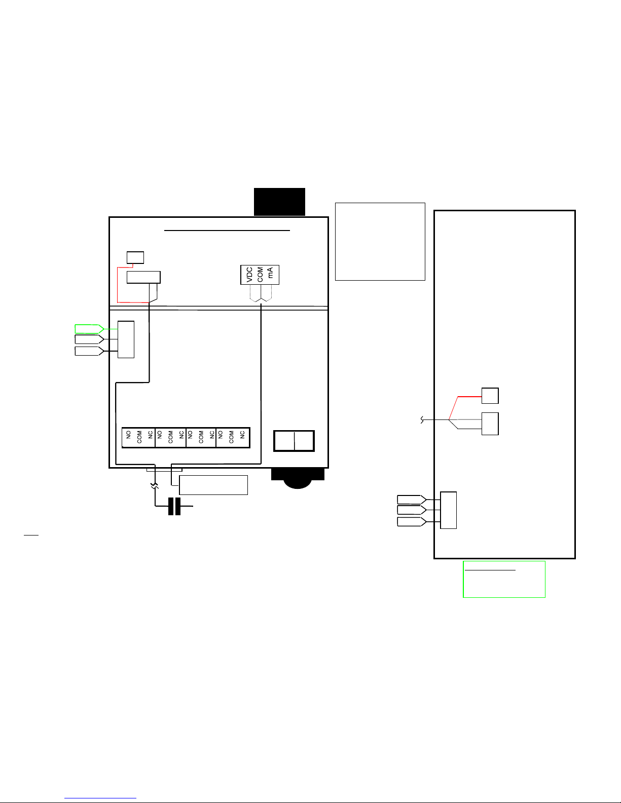
Notes
:
1. Power Cord - Provided w/ wall plug connector and 8 Ft. 3 conductor wire.
2. Audible and Visual Alarm (Optional) factory wired. Remote Audible and Visual Alarms
must be 120VAC and connected to terminal Strip on Lower Circuit Board.
3. Sensor Cable between HaloguardIR Controller and IR Sensor Module - Maximum Length 1000FT. Use,
3 conductor 18 or 20ga. w/ foil shield.
4. Analog Outputs (Optional) are either 0 - 5 to 10VDC, and 4 - 20mA.
5. If Optional scanner is installed, Red wire is connected to scanner terminal on upper circuit board.
Green
Line Cord
115 VAC
50/60Hz.
AC HOT
GROUND G
N
L
White
Black
Cable Color Code
White - S Signal
Black - G Ground
Red - Scan Scanner(Only)
Figure 11 - Wiring Diagram
Plug in DIN Connector
AC COMMON
(3)
Cable to
IR Sensor
Module
Table of contents
Other Thermal Gas Systems Monitor manuals


