Thermal-Grip IP50D Guide

MODEL
GAS INSULATION NAILER
SAFETY OPERATION MANUAL
IP50D


IMPORTANT INFORMATION TO READ BEFORE
OPERATION.
Read and understand tool labels
and all operating instructions,
safety precautions and warningsin
this manual before operating or
maintaining this tool.
Failure to follow warnings could result in DEATH
or SERIOUS INJURY.
Most accidents that result from the operation and
maintenance of Nailers are caused by the failure
to observe basic safety rules or precautions. An
accident can often be avoided by recognizing a
potentially hazardous situation before it
occurs, and by observing appropriate safety
procedures.
Basic safety precautions are outlined in the
“SAFETY” section of this Manual
Hazards that must be avoided to prevent bodily
injury or machine damage are identified by
DANGERS and WARNINGS on the Nailer and in
this Manual
Never use this Nailer for applications other than
those specified in this Manual.
SAFETY
IMPORTANT SAFETY INSTRUCTIONS FOR
USING NAILERS
READ ALL INSTRUCTIONS
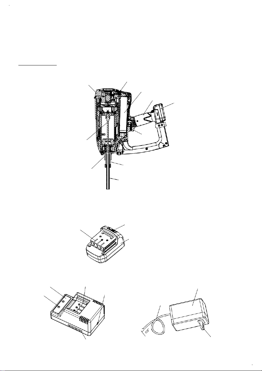
This Nailer is powered by an
internal combustion device.
This Nailer shall only be used with
dispensers for combustible gas
which are listed in this manual.
DANGER
1.
OPERATORS AND OTHERS IN WORK AREA
MUST WEAR SAFETY GLASSES WITH SIDE
SHIELDS.
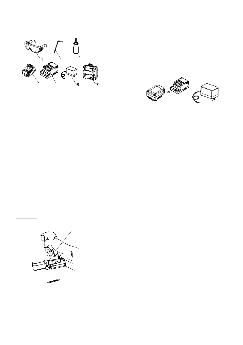
When operating the Nailer, always
wear safety glasses with side
shields, and make sure others in
work area wear safety glasses.
2.
NEVER USE IN PRESENCE OF FLAMMABLE
LIQUIDS OR GASES.
This Nailer must not be used in a
combustible environment or in
presence of flammable liquids or
gases, e.g. lacquer, paint, benzine,
thinner or gasoline.
This Nailer produces hot exhaust gases that
may ignite flammable materials and produces
sparks during operation.
3.
DO NOT TOUCH AROUND THE EXHAUST
OUTLET.
This Nailer produces hot exhaust
gases that may flammable materials.
The pus h lever and nose will
become hot and get heated up after
prolonged or rapid use.
Do not touch with bare hands.
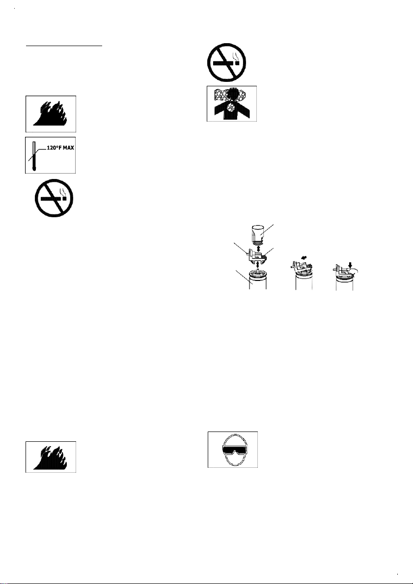
4.
EXPLOSION AND FIRE HAZARD.
The fuel cell is an aerosol dispenser
with flammable contents.
Press ured contai ner and the
propellant will remain in the fuel cell.
Faillure to follow instructions may
result in explosion or fire.
1
MAX
Keep the Nailer, fuel cells and battery
away from tem pera tures
exceeding 120°F (50°C).
Fuel cell and/or battery may burst,
releasing flammable gas.
Do not pierce or burn the container,
even after use.
Do not incinerate, refill, reclaim or
recycle the fuel cell.
Do not spray into a flame or any
incandescent material.
Keep away from ignition sources
No smoking.
Keep out of the reach of children.
120°F

WARNING
9.
STORE NAILER PROPERLY WITH FUEL CELL
AND BATTERY REMOVED.
When not in use, the Nailer, fuel cell and battery
should be stored in tool case and in a dry place.
Store indoors at temperature41°F(5°C) ~77°F(25°C).
Keep the Nailer, fuel cell and battery out of
direct sunlight and out of vehicle.
Keep out of reach of children.
10.
KEEP WORK AREA CLEAR.
5.
NEVERPOINTTOOLAT YOURSELF OR OTHERS
IN WORK AREA.
Always assume the Nailer contains
fasteners.
Never point the Nailer at yourself or
others, whether it contains fasteners
or not.
If fasteners are mistakenly driven, it can lead to
severe injuries.
6.
KEEP FINGERS AWAY FROM TRIGGER
WHE N NOT DRIVING FASTENERS TO
AVOID ACCIDENTALFIRING.
Never carry the Nailer with finger on trigger
since you could drive a fastener unintentionally
and injure yourself or someone else.
Always carry the Nailer by the handle only.
7.
ALWAYS WEAR EAR AND HEAD PROTECTION.
Always wear ear protection to protect your ears.
Always wear head protection to protect your head
from flying objects.
8.
USEOUTSIDE OR WELL-VENTILATEDAREAS.
This Nailer shall not be used in
enclosed or poorly ventilated areas.
This Nailer exhausts carbon
monoxide which is a danger to
health when inhaled.
Do not inhale.
2
11.
DRESS PROPERLY.
Always wear proper protective clothing on jobsite.
12.
KEEP ALL SCREWS AND COVERS TIGHTLY
IN PLACE.
Keep all screws and covers tightly mounted.
Check their condition periodically.
Never use the Nailer if parts are missing or
damaged.
13.
DO NOT LOAD FASTENERS WITH TRIGGER
OR PUSH LEVER DEPRESSED.
When loading fasteners into the Nailer,
1)
do not depress the trigger;
2)
do not depress the push lever;
3)
keep the Nailer pointed downward.
14.
KEEP FACE, HANDS ANDFEETAWAYFROM
FIRING HEAD DURING USE.
Never place your face, hands or feet closer than
8 inches (200 mm) from the firing head.
A serious injury can result if the fasteners are
deflected by the workpiece, or are driven away
from the point of entry.
15.
PLACE NAILER PROPERLY ON WORKPIECE.
Do not drive fasteners on top of other fasteners
or with the Nailer at too steep of an angle.
16.
CHECK FOR LIVE WIRES.
Avoid the risk of severe electrical shock by
checking for live electrical wires that may be
hidden by walls, floors or ceilings. Turn off the
breaker switch to ensure there are no live wires.
17.
DO NOT OVERREACH.
Keep proper footing and balance at all
times. Do not operate the nailer on a
scaffold and ladder.

18.
NEVER USE NAILER WHICH IS DEFECTIVE
OR OPERATING ABNORMALLY.
If the Nailer appears to be operating unusually,
making strange noises, or otherwise appears
defective, stop using it immediately and arrange
for repairs by a dealer authorized service center.
19.
TAKE FUEL CELL AND BATTERY OUT OF
NAILER WHEN:
1)
doing maintenance and inspection;
2)
clearing a jam;
3)
it is not in use;
4)
leaving work area;
5)
moving it to another location;
6)
handing it to another person.
Never attempt to clear a jam or repair the Nailer
unless you have taken fuel cell and battery out of
the Nailer and removed all remaining fasteners
from the Nailer.
20.
HANDLE NAILER CORRECTLY.
Operate the Nailer according to this Manual.
Never allow the Nailer to be operated by children,
individuals unf amiliar with its operation or
unauthorized personnel.
21.
NEVER USE NAILER FOR APPLICATIONS
OTHER THAN THOSE SPECIFIED IN THIS
MANUAL.
22.
HANDLE NAILER CAREFULLY.
Do not drop the Nailer or strike the Nailer against
hard surfaces. Handle the Nailer carefully.
23.
MAINTAIN NAILER WITH CARE.
Keep the Nailer clean and lubricated for better
and safer performance.
24.
USE ONLY PARTS, ACCESSORIES OR
FASTENERS SUPPLIED OR RECOMMENDED
BY DEALER.
Unauthorized parts, accessories, or fasteners
may void your warranty and can lead to malfunction
and resulting injuries.
Only service personnel trained by dealer,
distributor or employer trained personnel shall
repair the Nailer.
25.
NEVER MODIFY OR ALTER A NAILER. Doing
so may cause it to malfunction and personal
injuries may result.
3
FUEL CELL IMPORTANT SAFETY INSTRUCTIONS
DANGER
■
Fuel cell, fuel and propellant are flammable
under pressure.
Explosion / Fire Hazard
Must follow all instructions
otherwise it may result in fire
and explosion when handling
dispensers for combustible gas for
the purpose
of storage, transportation, inserting into and
taking out of the tool and disposal.
■
Do not smoke when handling the fuel cell.
WARNING Do not inhale its contents.
Expanding gases cause low temperatures.
Fluid gases might cause injuries when getting
in touch with skin oreyes.
In case of contact with skin ; wash the contact
surface carefully with warm water and soap.
In case of contact with eyes ; rinse the open eyes
under running water.
Contact a doctor if necessary.
Store in well-ventilated area.
Store under 41°F (5°C) ~77°F (25°C )(e.g .
Do not store under the direct sunlight or in a
vehicle).
Do not expose to an open flame and sparks.
Do not puncture or open the fuel cell.
Do not refill, reclaim or recycle the fuel cell.
Dispose of according to local regulations for
aerosol products.
Do not dispose of fuel cell with other scrap for
recycling.
Keep out of reach of children.

8.
Do not operate battery charger with damaged
cord or plug.
9.
Do not disassemble battery charger.
10.
Please read this Manual before using the battery
charger.
IMPORTANT SAFETY INSTRUCTIONS FOR USE
OF THE BATTERY AND BATTERY CHARGER
You must charge the battery before you use the
Nailer. Before using the model 503.1.16.001.01
battery charger, be sure to read all instructions and
cautionary statements on the battery and in this
manual.
REMEMBER : ONLY USE BATTERY
TYPE:No.503.1.10.001.01.
OTHER TYPES OF BATTERIES MAY BURST
AND CAUSE INJURY!
Follow these instructions to avoid the risk of injury:
WARNING
Improper use of the battery or battery charger
can lead to serious injury. Toavoidtheseinjuries:
1.
DO NOT disassemble the battery.
2.
DO NOT incinerate the battery.
3.
DO NOT short-circuit the battery.
4.
DO NOT insert any objects into the battery
charger's air vents. Electric shock or
damage to the battery charger may result.
5.
DO NOT charge outdoors. Keep the battery away
from direct sunlight and use only where
there is low humidity and good ventilation.
6.
DO NOT charge when the temperature is below
50°F (10°C) or above 104°F (40°C).
7.
DO NOT connect two battery chargers together.
8.
DO NOT insert foreign objects into the hole for
the battery or the battery charger.
9.
DO NOT use a booster transformer when charging.
10. DO NOT store the battery or battery charger in
places where the temperature may reach or
exceed 104°F (40°C).
DISPOSAL OF THE BATTERY
WARNING
Dispose of damaged or worn out batteries
according to local recycling or refuse rules.
4
IMPORTANT SAFETY INSTRUCTIONS FOR
BATTERY CHARGER
WARNING
Death or serious bodily injury could result from
improper or unsafe use of battery chargers.
To avoid these risks, follow these basic safety
instructions:
READ ALL INSTRUCTIONS
1.
This manual contains important safety and
operating instructions for battery charger Model
504.4.04.013.XX.
2.
Before using battery charger, read all instructions
and cautionary markings on (1)nailer,(2) battery
charger, (3) battery.
3.
To reduce risk of injury, only use rechargeable
battery type504.4.04.011.01. Other type of
batteries may burst causing personal injury and
damage.
4.
Do not expose battery charger to rain or snow.
5.
Use of an attachment not recommended or sold
by the battery charger manufacturer may result
in a risk of fire, electric shock, or injury to persons.
6.
Make sure cord is located so that it will not be
stepped on, tripped over, or otherwise subjected
to damage.
7.
An extension cord should not be used unless
necessary.
Use of improper extension cord could result in a
risk of fire and electric shock.

SPECIFICATION
1.
GAS INSULATION NAILER
TYPE
IP50D
Type of power
Piston reciprocating
Applicable nails
See 2. Available Nails.
Nail Capacity
1 nails
Ambient temperature
-5 ℃~ 50℃(23℉to 120℉)
Dimensions
18.30 "(L)×14.55"(H)×4.80"(W)
465mm(L)×370mm (H)×122mm (W)
Weight
8.2lbs. (3.7kg Include battery )
Cycle Rate
1 nails/second
Battery Pack
NiMH 7.2V
2.
Available Nails
WARNING
Be sure to use only the genuine dealer nails as the above sizes. The use of any other nails can result in
tool malfunction or nail breakdown, leading to serious injuries.
Only nails shown in the above table can be driven with this Nailer.
3.
Fuel cell
Fuel Cell
Sold Separately, Specification as below:
1 )Φ31.5mm x 165mm Pressure 16 ~18 bar,
Using temperature range: 23 ℉(-5℃)~120℉(50℃)
Model No: FC165-1-1
2 )Φ31.5mm x 165mm Pressure 10.8 ~11.8 bar,
Using temperature range: 23 ℉(-5℃)~120℉(50℃)
Model No: FC165-2-1
4.
Charger
Input power source
AC110 ~240V / 50 ~60Hz
Charge time
Charging voltage
DC 12V
Charging current
DC 0.8A
Charger Weight
0.15Kg
Adapter Weight
0.085Kg
5
30-160mm
About 60minutes

GENERAL OPERATION MANUAL
NOTE:
The information contained in this Manual is designed to assist you in the safe operation of the Nailer.
Some illustrations in this Manual may show details or attachments that differ from those on your own
Nailer.
NAME OF PARTS
1. Gas Insulation Nailer ( MODEL: IP50D )
Cap
Piston Assembly
Fuel Cell Door
Fuel Cell
Handle Battery Pack
Trigger
Fastener guide Support Guide Sleeve
Fastener guide
2. Battery Pack( 503.1.10.001.02)
Terminal
Latch
Battery Pack
3.
Battery Charger(503.1.16.001.02) (include Adapter and Charger Base)
6
Power Cord
Charger Base Battery Installation Charger Adaptor
Light Indication Connection
Air Vent Connection Plug Power Plug

4.
Accessories
2 3
4 5
DANGER
Accessories other than those shown below can lead
to malfunction and resulting injuries.
STANDARD ACCESSORIES
1.
How to install the battery
Align the battery with the groove in tool handle
and slip it into place. Always insert it all the way
until it locks in place with a little click. If not, it
may accidentally fall out of the tool, causing
injury to you or someone around you.
2.
How to remove the battery
Withdraw battery from the tool handle while
pressing top button on the battery.
1.Safety Glasses····································
2.
Wrench M5
·······································
3.
lubricating oil
·····································
4.BatteryPack······································
5.Charger Base ·····································
6.Charger Adaptor··································
7.Blow Case Assembly ····························
OPTIONAL ACCESSORIES
sold separately
1.Fuel Cell
2.Cleaner
REMOVAL AND INSTALLATION METHOD OF
BATTERY
Handle
Latch
Battery Pack
pull out
STEP:
1.
Insert the battery into the charger base. Make
sure it contacts the bottom of the charger base .
2.
Insert the connection plug of adapter into the
receptacle of the charge base.
3.
Insert the power plug of the adapter into the
plug seat.
4.
Charging
■When the charger adapter has been inserted into the
plug seat , charging will commence and the red &
green pilot lamp will light up together.
■When done charging, the red light will turn
off and only green light will be on.
7
NOTE: The battery charging time becomes longer
when a temperature is low or the voltage of
the power source is too low.
5.
Disconnect battery charger from the power plug.
CAUTION
■
If the battery is recharged when it is warm due
to battery use or exposure to sunlight, thepilot
lamp may not light. The battery will not be
recharged. In such a case, let the battery cool
before charging.

BEFORE OPERATION
Read section titled “SAFETY”
Make sure of the followings before operation.
WORKING ENVIRONMENT
WARNING
■
No flammable gas, liquid or other
flammable objects at worksite.
■
Use outside or well- ventilated
areas. Do not inhale.
■
Keep the Nailer, fuel cell and
battery away from sunshine and
from temperature exceeding
120°F (50°C).
■
Keep away from ignition sources.
No smoking.
■
Clear the area of children or
unauthorized personnel.
COLD WEATHER CARE
■
Do not store the Nailer, fuel cell and battery in a
cold weather environment. Keep the Nailer, fuel
cell and battery in a warm area until beginning
the work.
■
If the Nailer, fuel cell and battery are already
cold, bring it in a warm area and allow the Nailer
to warm up before use. Observe temperature
limit of max. 120°F (50°C).
Do not expose to an open flame and sparks!
CAUTION
■
This Nailer may not drive completely when:
at low temperature fuel cell may lose the
required propellant force;
or at high temperature.
■
Do not use the Nailer in the rain or where
excessive moisture is present.
PREPARING THE FUEL CELL
Read section titled “FUEL CELL IMPORTANT
SAFETY INSTRUCTIONS ”
DANGER
■
The fuel cell is flammable.
■
Keep away from ignition sources.
8
(50℃)
CAUTION
■
Do not spray into flame or any
incandescentmaterial.
■
Do not smoke when handling
fuel cell.
■
Keep stem of fuel cellawayfrom
face or skin. Expanding gases
cause low temperatures.
■
Do not inhale.
■
Keep out of reach of children.
■
If the gas leaks from the metering valve orthe
gascartridge after attachingthemeteringvalve,
replace with the new metering valve.
■
Do not attempt to reuse the metering valve.
Replace with the new metering valve.
To attach the metering valve to a fuel cell:
Cap
Stem
Fuel Cell
Metering Valve
(1)
Separate the metering valve and the cap from
the gas cartridge.
(2)
Stem downward, put the metering valve inclined
forward to the bowl cover.
(3)
Press downward on the rear of the metering valve
until it seals, no gas leakage.
Check the metering valve:
Press the metering valve stem on fuel cell two or
three times against a stationary object and
release.
If gas is not dispersed, fuel cell is empty.
TESTING THE NAILER
DANGER Operatorsand others in work area
MUST wear safety glasses with
side shields.
WARNING
Never use Nailer unless push lever is operating
properly.

(3) INSERT FUEL CELL INTO
NAILER.
①Pulling the latch and open the cell cover.
(2) Installing the battery.
Handle
Trigger Fuel Cell Door
②Insert the fuel cell into nailer.
Fuel Cell
③Insert the stem of fuel cell into the hole of
adaptor.
Battery Pack
Insert
Make sure the battery indicator light is flashing green.
If the battery indicator light is flashing red, the battery
doesn't have enough power and it needs to be charged.
BATTERY INDICATOR LIGHT
Battery Indicated Light
Flashing GREEN: Enough power remaining
(The light turns steady during operation).
Flashing RED: Insufficient power remaining
(The light turns steady during operation).
Adapter
Stem
④Close the fuel cell door.
⑤Lock up the latch.
Stem
Fuel Cell
9
Latch
Fuel Cell Door
Fastener Guide

MAINTENANCE
NOTE:
■
The information contained in this Manual is designed
to assist you in the safe maintenance of the Nailer.
■
Some illustrations in this Manual may show details
or attachments that differ from those on your own
Nailer.
MAINTENANCE AND INSPECTION
Read section titled “SAFETY”.
DANGER
■
Never use and test inpresence
of flammable liquids or gases.
■
Keep away from ignitionsource.
Note After completion of each cleaning, drip the
lubricating oil (504.6.03.001.01) into the
nailer, which is shown in attachment Gas
Insulation Nailer Cleaning Guide .
If you have any questions about of the cleaning
operating procedures and methods, please contact
with dealer authorized service center.
WARNING
■
No smoking.
1. Daily cleaning
Users must regularly clean the nailer.,Remove
the internal accumulation of,carbon and dust to
ensure the normal operation.
Follow the attachment Gas Concrete Nailer
Cleaning Guide.
2.
Storing
DANGER
■
Store Nailer properlywithnails,
fuel cell and batteryremoved .
■
Thefuelcellisanaerosol
dispenserswith flammable
contents.
■
When not in use, the Nailer, fuel celland battery
should be stored in tool caseandin a dryplace
and below temperature 122°F (50°C).
■
Store indoors at temperature 41°F (5°C) ~77°F
(25°C).
■
When not in use for an extended period, apply a
thin coat of the lubricant to the steel parts to avoid
rust.
■
Do not store the Nailer / fuel cell and battery in a
cold weather environment.
10

EXPLODED DRAWING AND PARTS LIST
GAS INSULATION NAILER
MODEL: IP50D
25
201
26
1
28 27
2
29
30
3 5
31
4 6
7 832
33
9
34
12 10 35
11
13
14 41
15 42
16 11 43
22 23 52
17 51
202
18
203
46
47
48
49
11
24
50
44
45

12
EXPLODED DRAWING AND PARTS LIST
GAS INSULATION NAILER
MODEL: IP50D
53
54
55
56
57
58
63 59
61
62 64 60
70 71
72
73
65
66
67
68
65 69 59
70
74
75
59
501
502
503
504
505
506
507
76

13
PART LISTGSN50D
Note: Wearing parts
No.
Parts Name
Qty
1
Grille
1
2
Filter
1
3
ScrewM5 x30
4
4
Cap
1
5
Fuel Cell Door
1
6
Cap Shaft
1
7
Washer d=5
2
8
O-Retaining Ring 3.5 x2
2
9
Fuel Rubber
1
10
Fuel Dosing Lever
1
11
Screw M4x10
3
12
Retaining Ring d0=24
1
13
Motor Assembly
1
14
Anti-dust Plate
1
15
Motor Rubber Gasket
1
16
Motor Sleeve
1
17
Spark Plug
1
18
Cylinder Head
1
19
O- Ring φ59.92 xd3.53
1
20
Fan Blade Assembly
1
21
Screw M4 x5
1
22
Bracket
1
23
Fuel Cell Adaptor
1
24
Air Dam
1
25
Combustion Chamber Assembly
1
26
Parallel Pinφ 4 x60
2
27
Lock Bar
1
28
Rubber Stop
2
29
Retaining Ring d0=62
1
30
Piston Ring 60 x0.8
2
31
Piston Assembly
1
32
Bumper
1
33
O-Ring 70 x d3.53
1
34
Cylinder
1
35
Cylinder Assembly
1
36
Screw M5 x12
4
37
Muffler Cover
1
38
Muffler
1
39
Reed Valve
1
40
Reed Plate
1
41
Exhaust Baffle
1
42
Cage Sleeve
1
43
Spring Washer 0.5mm
1
44
Cage Spring d=1.6mm
1
45
Cage
1
46
Guide Sleeve
1
47
Fastener Guide Support
1
48
Screw M5 x20
4
49
Fastener Guide
1
50
Nut M18
1
No.
Parts Name
Qty
51
Nut M5
4
52
Housing
1
53
Right Side Handle
1
54
Trigger Spring Plate
1
55
Wire Clip
1
56
Screw ST2.9x8
1
57
Spark Unit Assembly
1
58
Sponge Bumper
1
59
Screw ST4.2 x20
5
60
Screw M5 x25
2
61
Nut M5
2
62
Fuel Cell Bumper
1
63
Hanger
1
64
Fan Switch Assembly
1
65
Screw ST2.2 x11
4
66
Trigger Spring
1
67
Ignition Switch Assembly
1
68
Motor Connection Wire Assembly
1
69
LED Light
1
70
Screw M5x10
2
71
Rubber Column
1
72
Rotating Shaft
1
73
Rotating Block
1
74
Trigger
1
75
Power Circuit Assembly
1
76
Left Side Handle
1
201
Cap Label
1
202
Specification Label
1
203
Logo Label
1
501
Charger Adaptor
1
502
Charger Base
1
503
Battery Pack
2
504
Iubricating Oil
1
505
Wrench M5
2
506
Safety Glasses
1
507
Blow Case Assembly
1

FOR WARRANTY INFO, TOOL REPAIR, OR GENERAL QUESTIONS
Contact us at:
(web) www.thermalgriptools.com
(email) [email protected]
(phone) 616-454-3100
Table of contents