manuals.online logo
Brands
  1. Home
  2. •
  3. Brands
  4. •
  5. Thermal Instrument Co.
  6. •
  7. Switch
  8. •
  9. Thermal Instrument Co. 62-9FS Installation instructions

Thermal Instrument Co. 62-9FS Installation instructions

1 | P a g e
Effective Date
7/10/2008
THERMAL INSTRUMENT Co.
217 Sterner Mill Road, Trevose, PA 19053
Telephone No. (215) 355-8400
Fax No. (215) 355-1789
Email: office@thermalinstrument.com
INSTALLATION, OPERATION
INSTRUCTIONS
FOR
FLOW SWITCHES
62-9FS & 600-9 FS
220VAC
110VAC
24 VDC
Factory Set
2 | P a g e
Effective Date
7/10/2008
62-9FS & 600-9 FS FEATURES
True mass flow for gases and liquids
All welded 316SS body standard
Special materials available for corrosion or abrasion resistance
Unobstructed flow path
Pipe sizes and fittings to suit applications
-250 to 800F service
-14.7 to 15,000 PSIG
Automatic pressure and temperature compensation
Protected precision RTD sensors
Explosion-proof construction
Single alarm levels = 2 flow point alarms (temp is optional within two alarm system)
Fail safe design
Calibration chart provided for each meter
Temperature alarm optional
Form C (SPDT) 5 amp relays
Field change for trip high/trip low
Field change for input power 115/230 VAC 15 Watts
24 VDC operation available
3 | P a g e
Effective Date
7/10/2008
INSTALLATION MODEL 600-9FS AND 62-9FS FLOW SWITCH
FIGURE #1& #2 PROVIDE OUTLINE DRAWINGS OF THE FLOW SWITCH, SHOWING FLOW CONNECTIONS
AND MOUNTING DIMENSIONS.
ALL FLOW WETTED PARTS ARE 316 STAINLESS STEEL.
THE FLOW SWITCH CAN BE MOUNTED HORIZONTALLY OR VERTICALLY, HOWEVER, WHEN MOUNTED
VERTICALLY FLOW DIRECTION MUST BE UPWARDS. THE FLOW SHOULD ENTER AT THE PORT MARKED
‘IN’ AND EXIT
AT THE PORT MARKED “OUT”.
THE METER SHOULD BE INSTALLED IN A STRAIGHT LINE. THIS LINE SHOULD
PREFERABLY BE THE SAME DIAMETER AS THE METER TUBE OR PIPE. THIS STRAIGHT LINE SHOULD
HAVE A MINIMUM LENGTH OF TEN (10) DIAMETERS AHEAD OF THE METER. LIKEWISE, A STRAIGHT
LENGTH OF THE PIPE OR TUBE AFTER THE METER SHOULD BE AT LEAST A LENGTH OF FIVE (5) PIPE
DIAMETERS.
WHERE PHYSICAL CONDITIONS PREVENT THIS, INFORM US IN ADVANCE AND WE WILL CALIBRATE
THIS METER UNDER ACTURAL OPERATING CONDITIONS.
FIGURE #3 & #4 SHOWS THE OVERALL EXTERNAL WIRING CONNECTIONS
POWER WILL BE LABELED ACCORDINGLY
4 | P a g e
Effective Date
7/10/2008
OPERATION – MODEL 600-9FS AND 62-9FS
WITH ALL CONNECTIONS HAVING BEEN COMPLETED AND TESTED, APPLY
POWER AND ALLOW A TEN (10) MINUTE WARM UP PERIOD.
CAUTION: FLOW AND TRANSDUCER MUST BE WIHTIN 50°C OF OPERATION
TEMPERATURE BEFORE POWER IS APPLIED. SENSORS MAY BE
DAMAGED IF TRANSDUCER TEMPERATUE IS LOWER THAN THIS
LIMIT OR CALIBRATION WILL NOT BE ACCURATE.
TRIP POINTS ARE FACTORY SET. HOWEVER, THE CALIBRATION CURVE PROVIDED CORRELATS FLOW
VERSUS FLOW SWITCH VOLTAGE THAT CAN BE USED TO ADJUST TRIP POINTS IN THE FIELD.
SEE Figure #3 and #4 FOR ADJUSTMENT PROCEDURE.
5 | P a g e
Effective Date
7/10/2008
Figure #1
6 | P a g e
Effective Date
7/10/2008
Figure #2
7 | P a g e
Effective Date
7/10/2008
Figure #3
8 | P a g e
Effective Date
7/10/2008
Figure #4
9 | P a g e
Effective Date
7/10/2008
GENERAL PRECAUTIONS TO BE OBSERVED
IN INSTALLING FLOWMETER WIRING
When the Thermal Flowmeter or Probe is supplied with an explosion-proof condulet, it must be installed with
approved wiring techniques. This calls for seals where the external wiring enters these condulets.
In the case where we have a large condulet on a Probe with multiple connections, we will have a fitting with as
large as a 1 2" pipe connection. If the contractor is reducing this to 2" fittings, he must be sure that these
reducers are sealed with a suitable electrical or Teflon tape. In like manner, the connectors he
uses must be of the sealed conduit type.
Water entering the system from either the power wiring or the interconnecting cable system is very serious and
can do damage to the metering system.
The explosion-proof type condulets are designed for that purpose only; they are not waterproof and if the
system is submerged, water will enter. In applications where there is undue exposure, it may be well to go to
auxiliary covering or sealing mechanisms. This may merely mean a plastic coating, a plastic bag, or in extreme
cases a housing.
The same rules apply also where the external wiring enters the electronic housings. These can be either the
explosion-proof type, or the NEMA 4 type. In either case adequate attention must be paid to sealing the
electrical incoming lines. The cover on the NEMA 4 case is gasketed in a very adequate manner. However, in
many cases the atmospheric and liquid leaks are at the point of entry of the external wiring or through the
conduit from the external wiring itself.
In cases where the NEMA 4 units are used in very hazardous atmospheres or corrosive, it is advisable to purge
the system to prevent corrosive attack on the electronics.
10 | P a g e
Effective Date
7/10/2008
11 | P a g e
Effective Date
7/10/2008
12 | P a g e
Effective Date
7/10/2008
13 | P a g e
Effective Date
7/10/2008
14 | P a g e
Effective Date
7/10/2008
15 | P a g e
Effective Date
7/10/2008
16 | P a g e
Effective Date
7/10/2008

This manual suits for next models

1

Popular Switch manuals by other brands

ADC ProPatch Programmable Series Specification sheet

ADC

ADC ProPatch Programmable Series Specification sheet

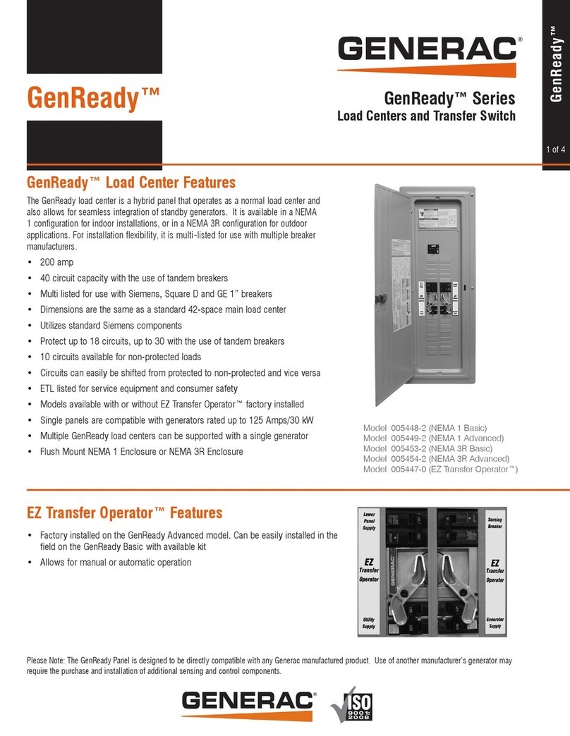
Generac Power Systems GenReady Series 005448-2 overview

Generac Power Systems

Generac Power Systems GenReady Series 005448-2 overview

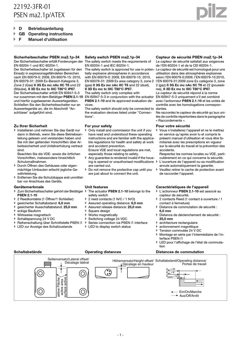
Pilz PSEN ma2.1p/ATEX operating instructions

Pilz

Pilz PSEN ma2.1p/ATEX operating instructions

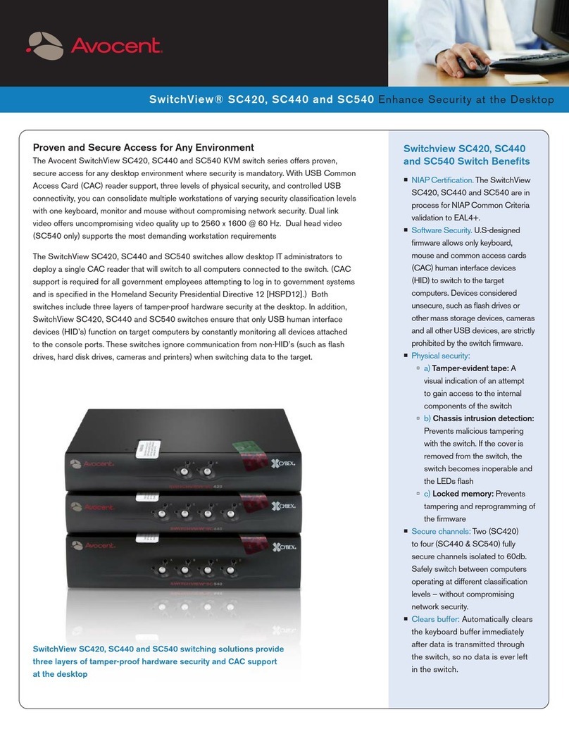
Avocent SwitchView SC420 specification

Avocent

Avocent SwitchView SC420 specification

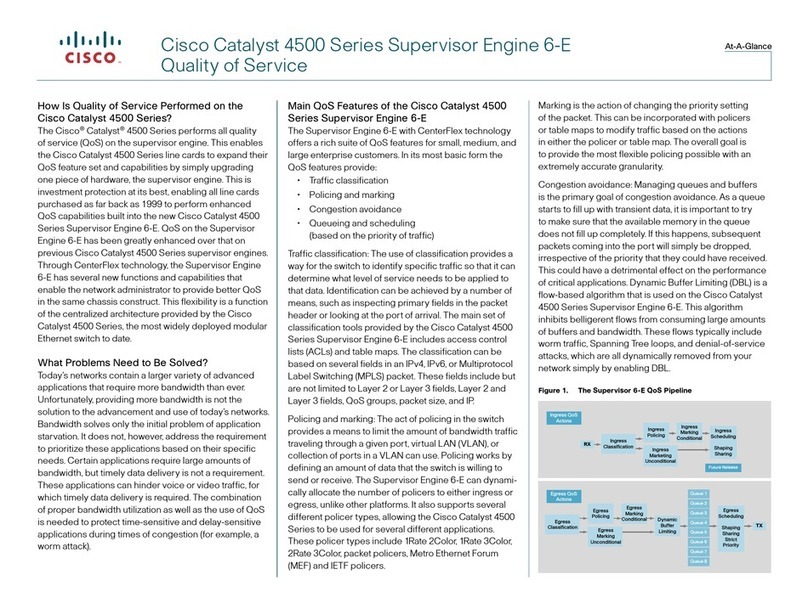
Cisco Catalyst 4507R-E supplementary guide

Cisco

Cisco Catalyst 4507R-E supplementary guide

Conceptronic CGIGA8A user manual

Conceptronic

Conceptronic CGIGA8A user manual

AMX DVX-2210HD-SP quick start guide

AMX

AMX DVX-2210HD-SP quick start guide

EUCHNER NZ1VZ EX Series operating instructions

EUCHNER

EUCHNER NZ1VZ EX Series operating instructions

Transition Networks SISTP1040-382B-LRT quick start guide

Transition Networks

Transition Networks SISTP1040-382B-LRT quick start guide

Digitus DN-650107 Quick installation guide

Digitus

Digitus DN-650107 Quick installation guide

DLI Pro user guide

DLI

DLI Pro user guide

Cisco Nexus 93108TC-FX3P Hardware installation guide

Cisco

Cisco Nexus 93108TC-FX3P Hardware installation guide

KVMSwitchTech HDMI-PIP-4P-MINI instruction manual

KVMSwitchTech

KVMSwitchTech HDMI-PIP-4P-MINI instruction manual

Murphy Dual Temperature SWICHGAGE MDTM89 Instructions for installation and operation

Murphy

Murphy Dual Temperature SWICHGAGE MDTM89 Instructions for installation and operation

LEGRAND Valena Life 7 521 84 quick start guide

LEGRAND

LEGRAND Valena Life 7 521 84 quick start guide

Intermatic T7805B supplementary guide

Intermatic

Intermatic T7805B supplementary guide

ExaSAN C1M quick start guide

ExaSAN

ExaSAN C1M quick start guide

THOMSON TS 870 - WITH TSC 80E CONTROLLER Service manual

THOMSON

THOMSON TS 870 - WITH TSC 80E CONTROLLER Service manual

manuals.online logo
manuals.online logoBrands
  • About & Mission
  • Contact us
  • Privacy Policy
  • Terms and Conditions

Copyright 2025 Manuals.Online. All Rights Reserved.