Thermalright TRUE Spirit 140 Direct User manual

Thermalright
TRUE Spirit 140 Direct

4
4
8
× 4 × 1
× 4 × 8
TRUE Spirit 140 Direct
Assembly package
× 5
× 3
× 5
× 4
× 4
× 1 × 1
× 4
× 1
× 1
TRUE Spirit 140 Direct
1
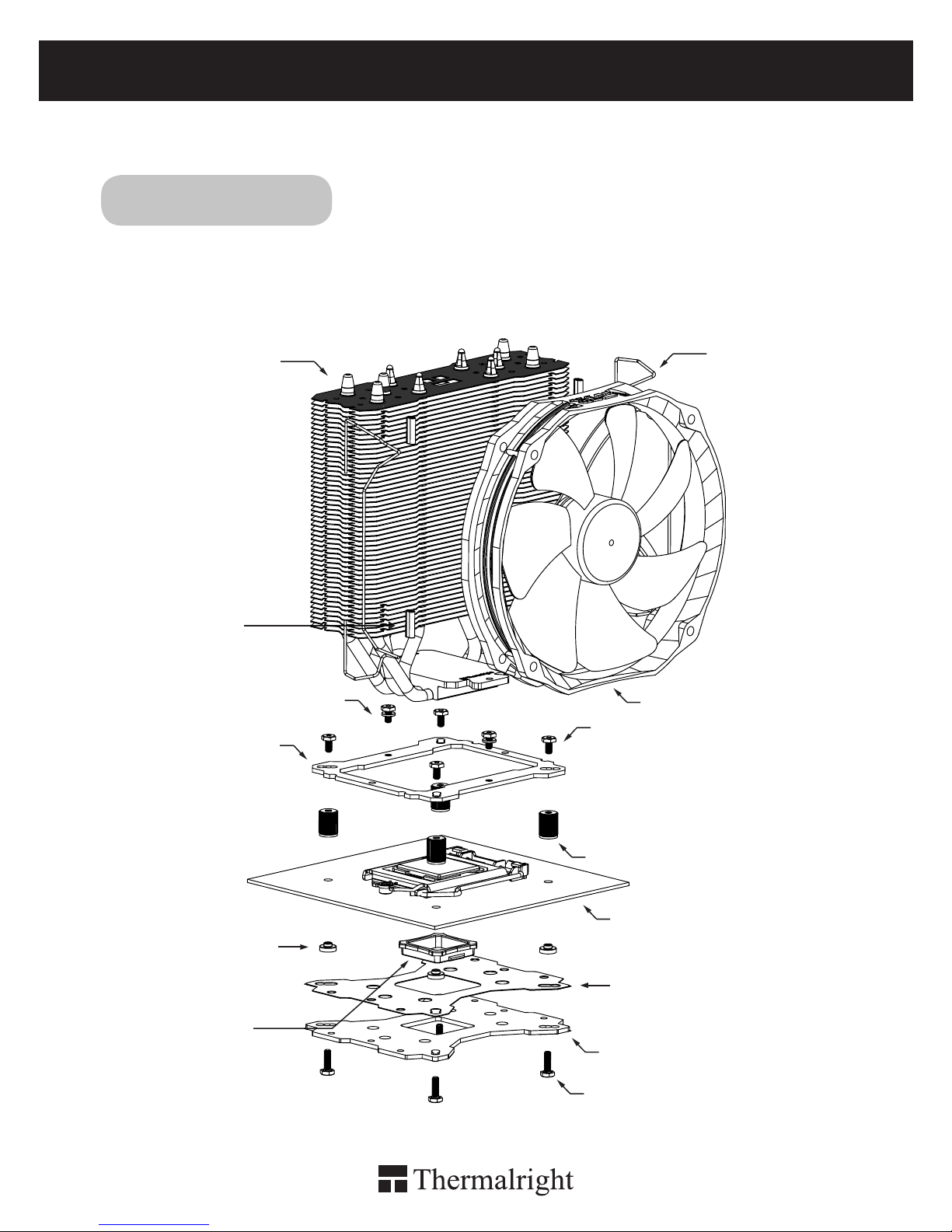
Exploded View
Important! Before proceeding with installation, please check for the most
up-to-date instructions at www.thermalright.com
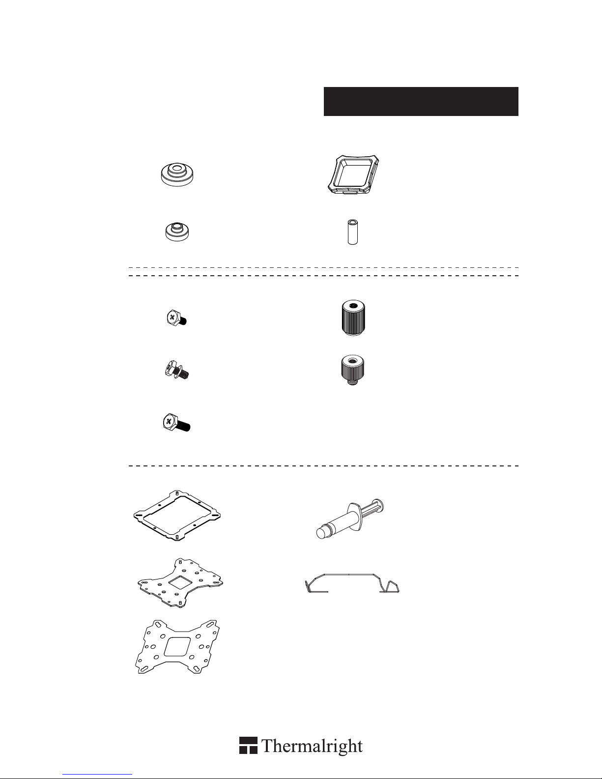
Intel 775/1150/1151/1155/1156/1366
Screw Nut
TY-140 Black
Anchoring Mount M3L6 Screw
M3L7 Screw
Metal Back Plate
Motherboard
M3L10 Screw
Mylar Film
Rubber Tubes
Intel Washer
(small)
Backplate cap
Fan Clip
Heatsink Body

The Ultimate Cooling Solutions!
www.thermalright.com
2
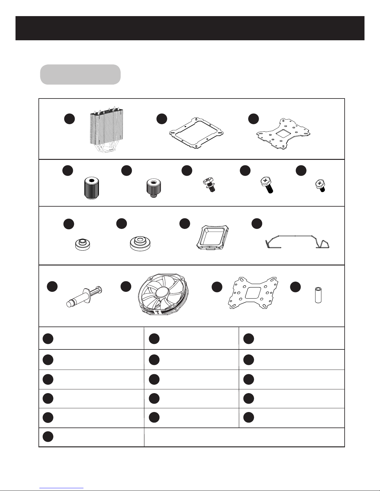
Component
1
1
2
2
3
3
4 5 6
7 8
9
9
10
13
16
11
14
14
12
15
15 16
13
TS-140 Direct
Heatsink Body ×1
AMD Washer (big) ×4
Mylar Film ×1
Backplate Cap ×1
Metal Back Plate ×1
M3L10 Screw ×5
M3L7 Screw ×3
Anchoring Mount ×1
Screw Nut ×4
M3 L6 Screw ×5
Chill Factor IV ×1
Rubber Tubes ×8
4 5 76 8
LGA2011 Type B
Screw Pillars x4
Intel Washer (small) ×4
Fan Clip ×4
TY-140 Black ×1
1110 12

3
Installation Instructions:
Step 1: Step 2:
Step 3:
Step 4:
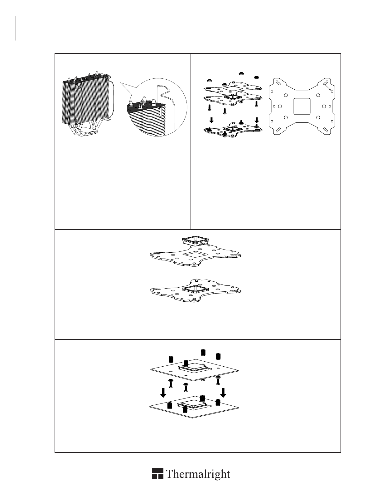
Step1 : Part Installation
Take out TS-140 Direct heat-sink from the
color box . Pull both ends of the Fan clip and
make them go through holes on the corners
of the heat-sink. (As shown in the picture.)
Repeat for the other fan clip. Leave both fan
clips on the heat-sink body for fan installation
later on . Insert the four black Rubber Tubes
(Noise damping use) into the four indents on
the front of the heat-sink body. Do not remove
them.
Step 3 : 775 Back Plate Cap
Note: When installing on a 775 platform, please first insert the Back Plate Cap into the opening on
the Back plate, make sure you have the Cap facing downwards. (Only for LGA775 platform, all other
platforms go directly to Step 4.).
Step 4 : Screw Cylinder Installation
Place the motherboard on top of the Back Plate. See the four Screw Pillars go through the four holes
around the processor socket.Cap the four Screw Pillars with the four Screw Nuts.Make sure the side
with a washer is facing the Back Plate.
12
4
3
Step 2 : Backplate Installation
Choose the platform (775/1150/1151/1155/1156/1366)
you are in use. Make four M3L10 Screw Pillars go
through the Metal Back Plate and the Mylar lm from
bottom towards top.And then place the Metal Back
Plate on the table. Put the four Washers (for Intel)
around the Screw Pillars.
1366
775
1150
1151
1155
1156

The Ultimate Cooling Solutions!
www.thermalright.com
4
Step 5: Step 6:
Step 7: Step 8:
Step 9:
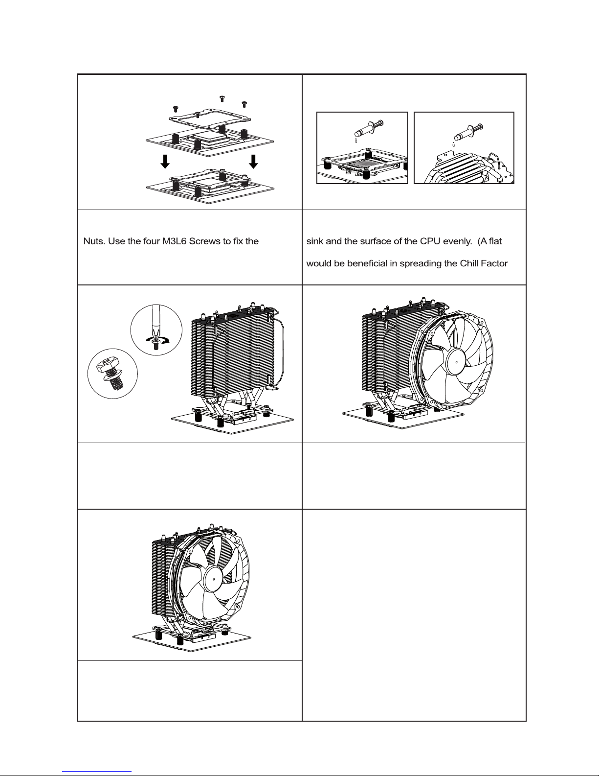
Step 8: Fan Installation
Place the included TY-140 Black onto the Heatsink
Body. And then secure it with the Fan Clips, by
pulling the Fan Clips to place the four ends at the
four holes on the TY-140 Black.
Step 6 : Apply the Chill Factor IV
Apply the Chill Factor IV to the base of the heat-
edge, like a business card or an old credit card
IV.)
Step 9: Installation completed
Plug in the fan connector to the CPU PWM Fan
socket on the motherboard. Installation complete.
Step 7: Easy Access
Place the Heatsink on top of the CPU. And then
use the two M3L7 Screws to secure the
Anchoring Mount.
12
4
3
Step 5 : Anchoring Mount Installation
Place the Anchoring Mount on the Screw
Anchoring Mount on to the Screw Nuts.
TRUE Spirit 140 Direct
5
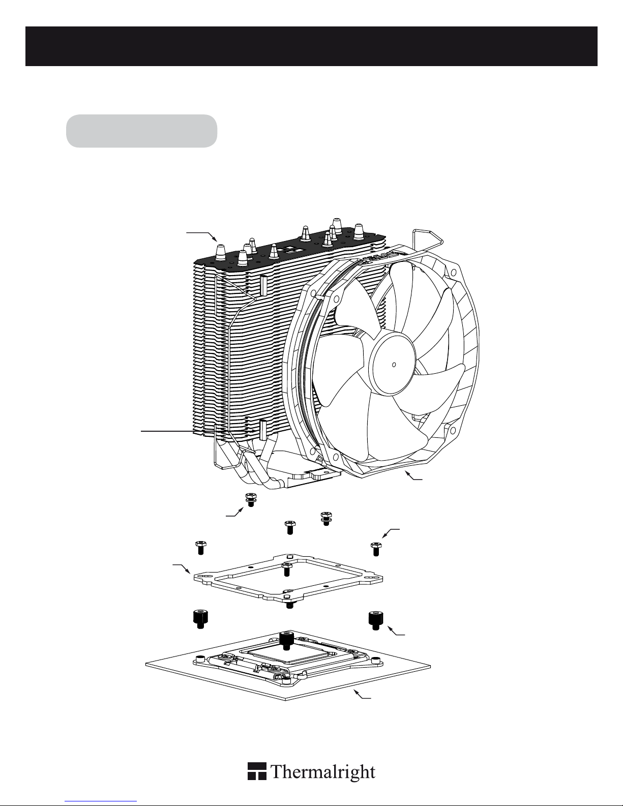
Exploded View
Important! Before proceeding with installation, please check forthe most
up-to-date instructions at www.thermalright.com
Anchoring Mount
LGA2011 Type B
Screw Pillars
Heatsink Body
M3L7 Screw
M3L6 Screw
Motherboard
Intel 2011/2011-3
TY-140 Black
Rubber Tubes

The Ultimate Cooling Solutions!
www.thermalright.com
6
Component
1
1
2
2
3
3
4 5 6
7 8
9
9
10
13
16
11
14
14
12
15
15 16
13
TS-140 Direct
Heatsink Body ×1
AMD Washer (big) ×4
Mylar Film ×1
Backplate Cap ×1
Metal Back Plate ×1
M3L10 Screw ×5
M3L7 Screw ×3
Anchoring Mount ×1
Screw Nut ×4
M3 L6 Screw ×5
Chill Factor IV ×1
Rubber Tubes ×8
4 5 76 8
LGA2011 Type B
Screw Pillars x4
Intel Washer (small) ×4
Fan Clip ×4
TY-140 Black ×1
1110 12

7
Step 1 : Screw Pillar Installation
Take out TS-140 Direct heat-sink from the color box . Pull both ends of the Fan clip and make
them go through holes on the corners of the heat-sink. (As shown in the picture.) Repeat for the
other fan clip. Leave both fan clips on the heat-sink body for fan installation later on . Insert the
four black Rubber Tubes (Noise damping use) into the four indents on the front of the heat-sink
body. Do not remove them.
Installation Instructions:
Step 1:
Step 2:
Step 3:
Step 2 : Screw Pillar Installation
Place the motherboard (the processor installed) on top of the desk or a workbench. Fix the four included
LGA2011 Type B Screw Pillars into the heat-sink studs on the Intel ILM Assembly Frame around the
processor socket in a criss-cross pattern.
Step 3 : Anchoring Mount Installation
Place the Anchoring Mount on the Screw Pillars. Use the four M3L6 Screws to x the Anchoring Mount
on to the Screw Pillars, also in a criss-cross pattern to ensure balanced mounting.
1
1
2
2
4
4
3
3

The Ultimate Cooling Solutions!
www.thermalright.com
8
Step 4:
Step 5:
Step 7:
Step 6 : Fan Installation
Place the included TY-140 Black onto the Heatsink
Body. And then secure it with the Fan Clips, by
pulling the Fan Clips to place the four ends at the
four holes on the TY-140 Black.
Step 4 : Applying Thermal Paste
n spreading the thermal paste.)
Step 7 : Installation completed
Plug in the fan connector to the CPU PWM Fan
socket on the motherboard. Installation complete.
Step 5: Easy Access
Place the Heatsink Body on top of the CPU. And
then use the two M3L7 Screws to secure
the Anchoring Mount.
Chill Factor
2g
Chill Factor
2g
Chill Factor
2g
Chill Factor
2g
Step 6:

TRUE Spirit 140 Direct
9
Exploded View
Important! Before proceeding with installation, please check for the most
up-to-date instructions at www.thermalright.com
AM2/AM2+/AM3/AM3+/FM1
Screw Nut
Anchoring Mount
AMD Washer (big)
Back Plate Cap
Heatsink Body
M3L6 Screw
M3L7 Screw
Metal Back Plate
Motherboard
M3L10 Screw
Mylar Film
TY-140 Black
Rubber Tubes
The Ultimate Cooling Solutions!
www.thermalright.com
10
Component
1
1
2
2
3
3
4 5 6
7 8
9
9
10
13
16
11
14
14
12
15
15 16
13
TS-140 Direct
Heatsink Body ×1
AMD Washer (big) ×4
Mylar Film ×1
Backplate Cap ×1
Metal Back Plate ×1
M3L10 Screw ×5
M3L7 Screw ×3
Anchoring Mount ×1
Screw Nut ×4
M3 L6 Screw ×5
Chill Factor IV ×1
Rubber Tubes ×8
4 5 76 8
LGA2011 Type B
Screw Pillars x4
Intel Washer (small) ×4
Fan Clip ×4
TY-140 Black ×1
1110 12
11
Installation Instructions:
Step 1:
Step 3:
Step 4:
Step1 : Part Installation
Take out TS-140 Direct heat-sink from the
color box . Pull both ends of the Fan clip and
make them go through holes on the corners
of the heat-sink. (As shown in the picture.)
Repeat for the other fan clip. Leave both fan
clips on the heat-sink body for fan installation
later on . Insert the four black Rubber Tubes
(Noise damping use) into the four indents on
the front of the heat-sink body. Do not remove
them.
Step 3 : Back Plate Cap
Note: When installing on an AMD platform, please rst insert the Back Plate Cap into the opening on the
Metal Back plate, make sure you have the Cap facing downwards.
Step 4 : Screw Cylinder Installation
Place the motherboard on top of the Back Plate. See the four Screw Pillars go through the four holes
around the processor socket.Cap the four Screw Pillars with the four Screw Nuts.Make sure the side
with a washer is facing the Back Plate.
Step 2:
Step 2 : Backplate Installation
Choose the platform (AMD) you are in use. Make four
M3L10 Screw Pillars go through the Metal Back Plate
and the Mylar lm from bottom towards top. And then
place the Metal Back Plate on the table. Put the four
Washers (for AMD) around the Screw Pillars.
AMD
12
3
4
The Ultimate Cooling Solutions!
www.thermalright.com
12
Step 5: Step 6:
Step 7: Step 8:
Step 9:
Step 8: Fan Installation
Place the included TY-140 Black onto the Heatsink
Body. And then secure it with the Fan Clips, by
pulling the Fan Clips to place the four ends at the
four holes on the TY-140 Black.
Step 6 : Apply the Chill Factor IV
Apply the Chill Factor IV to the base of the heat-
edge, like a business card or an old credit card
IV.)
Step 9: Installation completed
Plug in the fan connector to the CPU PWM Fan
socket on the motherboard. Installation complete.
Step 7: Easy Access
Place the Heatsink Body on top of the CPU. And
then use the two M3L7 Screws to secure the
Anchoring Mount.
Step 5 : Anchoring Mount Installation
Place the Anchoring Mount on the Screw
Anchoring Mount on to the Screw Nuts.
12
4
3

TRUE Spirit 140 Direct
25
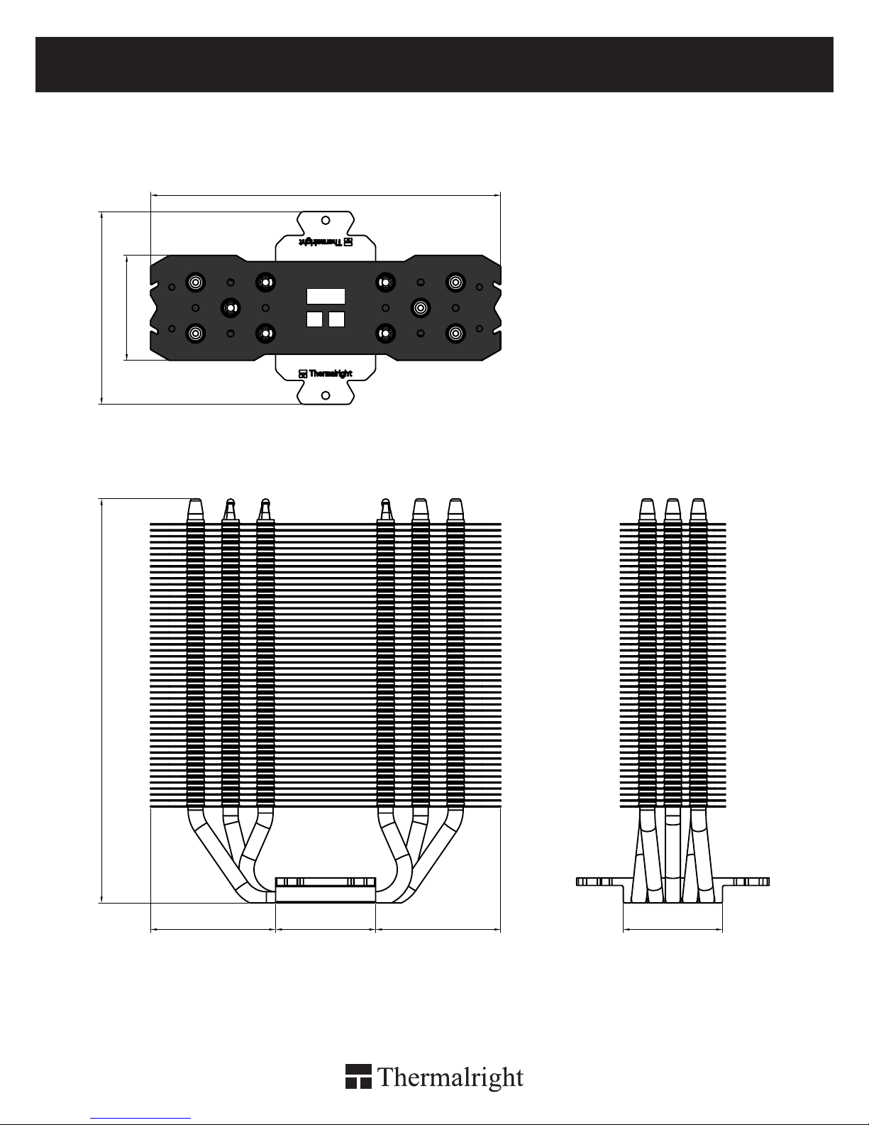
Technical Spec
Heatsink Specifications:
Dimension: Length 140mm x Width 77mm x Height 161mm
Weight: 500g
Heatpipe: 6mm heatpipe*5 units
Fan Specification:
Dimension: L152mm x H140mm x W26.5mm
Weight: 160g
Fan speed: 300~1300RPM
Fan noise: 15~21dBA MAX
Airflow: 16.9~73.6CFM MAX
Connector: 4 Pin (PWM Fan connector)
TRUE Spirit 140 Direct
27
140
77
42
161.48
40
50 50 39.7

The Ultimate Cooling Solutions!
www.thermalright.com
TEL: +886-2-2915-5005
FAX: +886-2-2915-5123
EMAIL: [email protected]

TRUE Spirit 140 Direct
29
Table of contents


