Français /
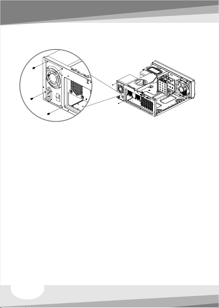
1. Dévissez et retirez la tige.
2. Dévissez et détachez la cage à
disque dur 3.5” du châssis.
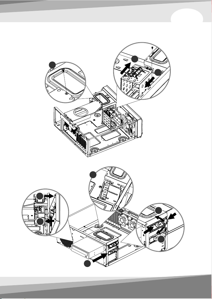
3. Poussez vers l'intérieur et vers le
haut pour déverrouiller le clip sans
outil sur la cage à disque dur 5.25”
4. Détachez le panneau avant du
châssis en poussant et relâchant
les 3 ressorts du panneau avant.
5. Insérez le périphérique 5.25” dans
la baie pour lecteur et poussez vers
l'intérieur et vers le bas pour
verrouiller le clip sans outil.
6. Sécurisez le périphérique 5.25”
avec des vis sur la côté opposé du
clip sans outil
7. Remettez la cage à disque dur 3.5"
dans son emplacement d'origine
dans le châssis et sécurisez-la avec
des vis.
8. Poussez pour remettre le panneau
avant dans son emplacement
d'origine.
Remarque: Pour un bon
fonctionnement de la baie de
lecteur 5.25”, il n'est pas
recommandé d'insérer le
périphérique 5.25" dans la seconde
ou troisième baie.
Español /
1. Desatornille y extraiga la vara.
2. Desatornille y separe el cajón del
HDD de 3,5 pulgadas del chasis.
3. Empuje hacia dentro y hacia arriba
para abrir el sujetador sin
herramientas del cajón del HDD de
5,25 pulgadas.
4. Separe el panel frontal del chasis
empujando y soltando los 3 muelles
del panel frontal.
5. Inserte el dispositivo de 5,25
pulgadas en la bahía de unidad y
empuje hacia dentro y hacia abajo
para cerrar el sujetador sin
herramientas.
6. Asegure, con tornillos, el
dispositivo de 5,25 pulgadas en el
lado opuesto del sujetador sin
herramientas.
7. Acople de nuevo el cajón del HDD
de 3,5 pulgadas en la posición
original del chasis y asegúrelo con
tornillos.
8. Presione para acoplar el panel
frontal de nuevo en la posición
original.
Advertencia: Si desea obtener un
funcionamiento correcto de la bahía
de unidad de 5,25 pulgadas, le
recomendamos que no inserte el
dispositivo de 5,25 pulgadas en la
2ª ó 3ª bahía.
English /
1. Unscrew and remove the rod.
2. Unscrew and detach the 3.5” HDD
cage from the chassis.
3. Push inward and upward to unlock
the tool-free clip on 5.25” HDD cage.
4. Detach the front panel from the
chassis by pushing and releasing
the 3 springs of the front panel.
5. Insert the 5.25” device into the
driver bay and push inward and
downward to lock the tool-free clip.
6. Secure the 5.25” device with screws
at the opposite side of the tool-free
clip
7. Attach the 3.5” HDD cage back to
the original location in the chassis
and secure it with screws.
8. Push to attach the front panel back
to the original location.
Notice: For correct operating 5.25"
drivebay, insert the 5.25" device
into the 2nd or 3rd bay is not
recommended.
Deutsche /
1. Lösen Sie die Schrauben und
entfernen Sie den Bügel.
2. Lösen Sie die Schrauben und
entfernen Sie den 3,5 Zoll HDD-
Käfig vom Gehäuse.
3. Drücken Sie einwärts und aufwärts,
um den Clip ohne Werkzeug auf
dem 5,25 Zoll HDD-Käfig zu
entsperren.
4. Entfernen Sie die Vorderseite vom
Gehäuse, indem Sie drücken und
die 3 Federn der Vorderseite
freigeben.
5. Führen Sie die 5,25 Zoll Einheit in
den Schacht ein und drücken Sie
einwärts und abwärts, um den
werkzeuglosen Clip zu befestigen.
6. Sichern Sie die 5,25 Zoll Einheit mit
Schrauben an den Seiten, die dem
werkzeuglosen Clip gegenüber
liegen.
7. Bringen Sie den 3,5 Zoll HDD-Käfig
wieder an seiner originalen Position
im Gehäuse an und sichern Sie ihn
mit Schrauben.
8. Drücken Sie, um die Vorderseite
wieder an ihren ursprünglichen
Platz zu bringen.
Hinweis: Für einen korrekt
arbeitenden 5,25 Zoll
Laufwerksschacht, wird es nicht
empfohlen, die 5,25 Zoll Einheit in
den 2. oder 3. Schacht einzubauen.
5
6