Sharp HT-DV30H User manual

HT-DV30H
SERVICE MANUAL
No. SX754HTDV30HH
Parts marked with " " are important for maintaining the safety of the set. Be sure to replace these parts with specified
ones for maintaining the safety and performance of the set.
This document has been published to be used
for after sales service only.
The contents are subject to change without notice.
PRECAUTIONS FOR USING LEAD FREE SOLDER
CHAPTER 1. GENERAL DESCRIPTION
[1] Safety Precaution For Service Manual ..........1-1
[2] Specifications ................................................ 1-1
[3] Names Of Parts .................................................... 1-2
CHAPTER 2. ADJUSTMENTS
[1] Servo Section ............................................... 2-1
[2] Test Mode ..................................................... 2-2
[3] DVD Test Mode............................................. 2-3
[4] DVD Firmware Update Test Mode ................ 2-4
CHAPTER 3. MECHANISM BLOCKS
[1] Caution On Disassembly ............................... 3-1
[2] Removing And Reinstalling The Main Parts . 3-4
CHAPTER 4. DIAGRAMS
[1] Main Block Diagrams ..................................... 4-1
[2] DVD/CD Block Diagrams ............................... 4-3
[3] Power Block Diagrams .................................. 4-5
CHAPTER 5. CIRCUIT DESCRIPTION
[1] Waveforms Of DVD/CD Circuit.................... 5-1
[2] Voltage ........................................................ 5-2
CHAPTER 6. CIRCUIT SCHEMATICS AND PARTS
LAYOUT
[1] Notes On Schematic Diagram..................... 6-1
[2] Types Of Transistor And LED...................... 6-1
[3] Schematic Diagram ..................................... 6-2
[4] Charts Of Connecting Wires........................ 6-28
[5] Wiring Side Of PWB .................................... 6-30
CHAPTER 7. FLOWCHART
[1] Troubleshooting............................................7-1
CHAPTER 8. OTHERS
[1] Function Table Of IC.................................... 8-1
[2] FL Display ................................................... 8-49
PARTS GUIDE
DVD CINEMA
HT-DV30H
MODEL
HT-DV30H DVD Cinema consisting of HT-DV30H
(main unit) and CP-DV30H (speaker system).
CONTENTS
• In the interests of user-safety (Required by safety regulations in
some countries) the set should be restored to its original
condition and only parts identical to those specified be used.
SHARP CORPORATION

HT-DV30H
– i –
AudioXL-MP150Service ManualXLMP150MarketE
PRECAUTIONS FOR USING LEAD-FREE SOLDER
1. Employing lead-free solder
Example:
Indicates lead-free solder of tin, silver and copper.
2. Using lead-free wire solder
When fixing the PWB soldered with the lead-free solder, apply lead-free wire solder. Repairing with conventional lead wire
solder may cause damage or accident due to cracks.
As the melting point of lead-free solder (Sn-Ag-Cu) is higher than the lead wire solder by 40 C, we recommend you to
use a dedicated soldering bit, if you are not familiar with how to obtain lead-free wire solder or soldering bit, contact our
service station or service branch in your area.
3. Soldering
As the melting point of lead-free solder (Sn-Ag-Cu) is about 220 C which is higher than the conventional lead solder
and as it has poor solder wet ability, you may be apt to keep the soldering bit in contact with the PWB for
extended period of time. However, since the land may be peeled off or the maximum heat-resistance temperature
of parts may be exceeded, remove the bit from the PWB as soon as you confirm the steady soldering condition.
Lead-free solder contains more tin, and the end of the soldering bit may be easily corrected. Make sure to turn on
and off the power of the bit as required.
If a different type of solder stays on the tip of the soldering bit, it is alloyed with lead-free solder. Clean the bit after
every use of it.
When the tip of the soldering bit is blackened during use, file it with steel wool or fine sandpaper.
Be careful when replacing parts with polarity indication on the PWB silk.
Lead-free wire solder for servicing
Ref No. Description
Parts No.
"MAIN, POWER, DISPLAY, SCART, VIDEO OUT, DIGITAL IN, DVD, MINUS FEEDBACK PWB" of this model employs
lead-free solder.
The LF symbol indicates lead-free solder, and is attached on the PWB and service manuals. The alphabetical character
following LF shows the type of lead-free solder.
by 40 C,
PWB-A 92LPWB7031MANS MAIN
PWB-B 92LPWB6891PWRS POWER (B1), DISPLAY (B2), SCART (B3), VIDEO OUT (B4), DIGITAL IN (B5)
PWB-C 92LPWB6891DVDS DVD
PWB-D 92LPWB7031SUBS MINUS FEEDBACK (USE FOR S/NO. 71100020 - 71200719 ONLY)

HT-DV30H
1 – 1
CHAPTER 1:GENERAL DESCRIPTION
[1] Safety Precaution For Service Manual
[2] Specifications
This product is classified as a CLASS 1 LASER PRODUCT.
WARNINGS
1- WHEN THE CABINET HAS BEEN REMOVED, THE POWER IS TURNED ON WITHOUT A COMPACT DISC,
AND THE PICKUP IS ON A POSITION OUTER THAN THE LEAD-IN POSITION, THE LASER WILL LIGHT FOR
SEVERAL SECONDS TO DETECT A DISC.
DO NOT LOOK INTO THE PICKUP LENS.
2- THE LASER POWER OUTPUT OF THE PICKUP INSIDE THE UNIT AND REPLACEMENT SERVICE PARTS
HAVE ALREADY BEEN ADJUSTED PRIOR TO SHIPPING.
3- NO ADJUSTMENT TO THE LASER POWER SHOULD BE ATTEMPTED WHEN REPLACING OR SERVICING
THE PICKUP.
4- UNDER NO CIRCUMSTANCES LOOK DIRECTLY INTO THE PICKUP LENS AT ANY TIME.
5- CAUTION - USE OF CONTROLS OR ADJUSTMENTS, OR PERFORMANCE OF PROCEDURES OTHER THAN
THOSE SPECIFIED HEREIN MAY RESULT IN HAZARDOUS RADIATION EXPOSURE.
THE AEL (ACCESSIBLE EMISSION LEVEL) OF LASER POWER OUTPUT FOR THIS MODEL IS SPECIFIED TO BE
LOWER THAN CLASS IREQUIREMENTS. HOWEVER, THE FOLLOWING PRECAUTIONS MUST BE OBSERVED
DURING SERVICING TO PROTECT YOUR EYES AGAINTS EXPOSURE TO THE LASER BEAM.
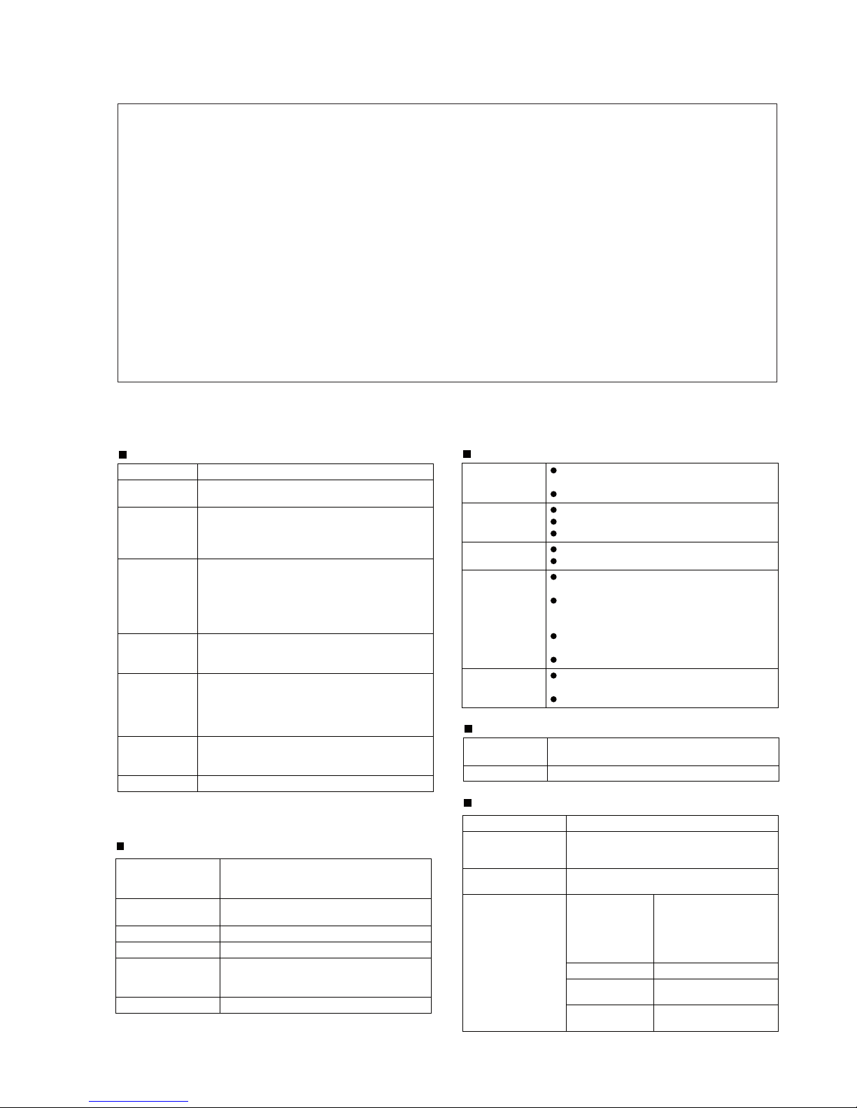
Main Unit
(*) This power consumption value is obtained when the
demonstration mode is cancelled in the power stand-by mode.
Power source AC 220 - 240 V ~ 50 Hz
Power
consumption
Power on: 65 W
Power stand-by: 0.6 W
Output power PMPO: 300 W
MPO: 150 W (75 W + 75 W) (DIN 45 324)
RMS: 150 W (75 W + 75 W) (DIN 45 324)
RMS: 90 W (45 W + 45 W) (DIN 45 500)
Video output
terminals
SCART output: SCART terminal x 1
Video output: RCA type x 1
S-video output: S-terminal x 1
Component video output: (Y/PB/PR) x 1
HDMI output : HDMI x 1
Support 480p/570p/720p/1080i output formats.
Audio input
terminals
Optical digital input (DIGITAL 1): Square type x 1
Optical digital input (DIGITAL 2): Square type x 1
Analogue input : 500mV/47k ohms
Audio output
terminals
Speakers: 4 ohms
Subwoofer Pre-out (audio signal): 1V/10K ohms
at 70 Hz
Headphones: 16 - 50 ohms
(recommended: 32 ohms)
Dimensions Width: 300 mm (11-13/16")
Height: 106 mm (4-1/8")
Depth: 300 mm (11-13/16")
Weight 3.8 kg (8.3 lbs.)
USB
Tuner
DVD player
Speaker
USB host
interface
Complies with USB 1.1/2.0 (Full Speed)
Mass Storage Class.
Support Bulk only and CBI protocol.
Support file MPEG 1 Layer 3
MPEG 2 Layer 3
WMA (Non DRM)
Bitrate support MP3 (32 - 320 kbps)
WMA (64 - 160 kbps)
Other Maximum total number of MP3/WMA files is
65 535.
Maximum total number of folders is 512
INCLUSIVE of root directory. (Folders which
have non playable files also counted.)
The ID3TAG information supported are
TITLE, ARTIST and ALBUM only.
Support ID3TAG version 1 and version 2.
File system
support
Support USB devices with Microsoft
Windows/DOS/FAT 12/FAT 16/FAT 32.
2 kbyte block length for sector.
Frequency
range
FM: 87.5 - 108 MHz
Other Maximum station can be stored is 30 preset.
Signal system PAL/NTSC colour
Supported disc
types
DVD (with the same region number at the
back of the unit), audio CD, CD-R, CD-RW,
JPEG, DivX (version 3 ~ 6)
Video signal Horizontal resolution: 500 lines
S/N ratio: 70 dB
Audio signal Frequency
characteristics
Linear PCM DVD:
20 Hz to 20 kHz
(sampling rate: 48 kHz)
20 Hz to 20 kHz
(sampling rate: 96 kHz)
CD: 20 Hz to 20 kHz
CD: 94 dB (1 kHz)S/N radio
Linear PCM DVD: 95 dB
CD: 94 dB
Dynamic range
Total harmonic
distortion ratio
0.01% maximum
Type 2-way type speaker system
2.5 cm (1") tweeter
12 cm (4-3/4") woofer
Maximum input
power
150 W
Rated input power 75 W
Impedance 4 ohms
Dimensions Width: 165 mm (6-7/16")
Height: 260 mm (10-1/4")
Depth: 229 mm (9-1/16")
Weight 3.1 kg (6.8 lbs.)/each
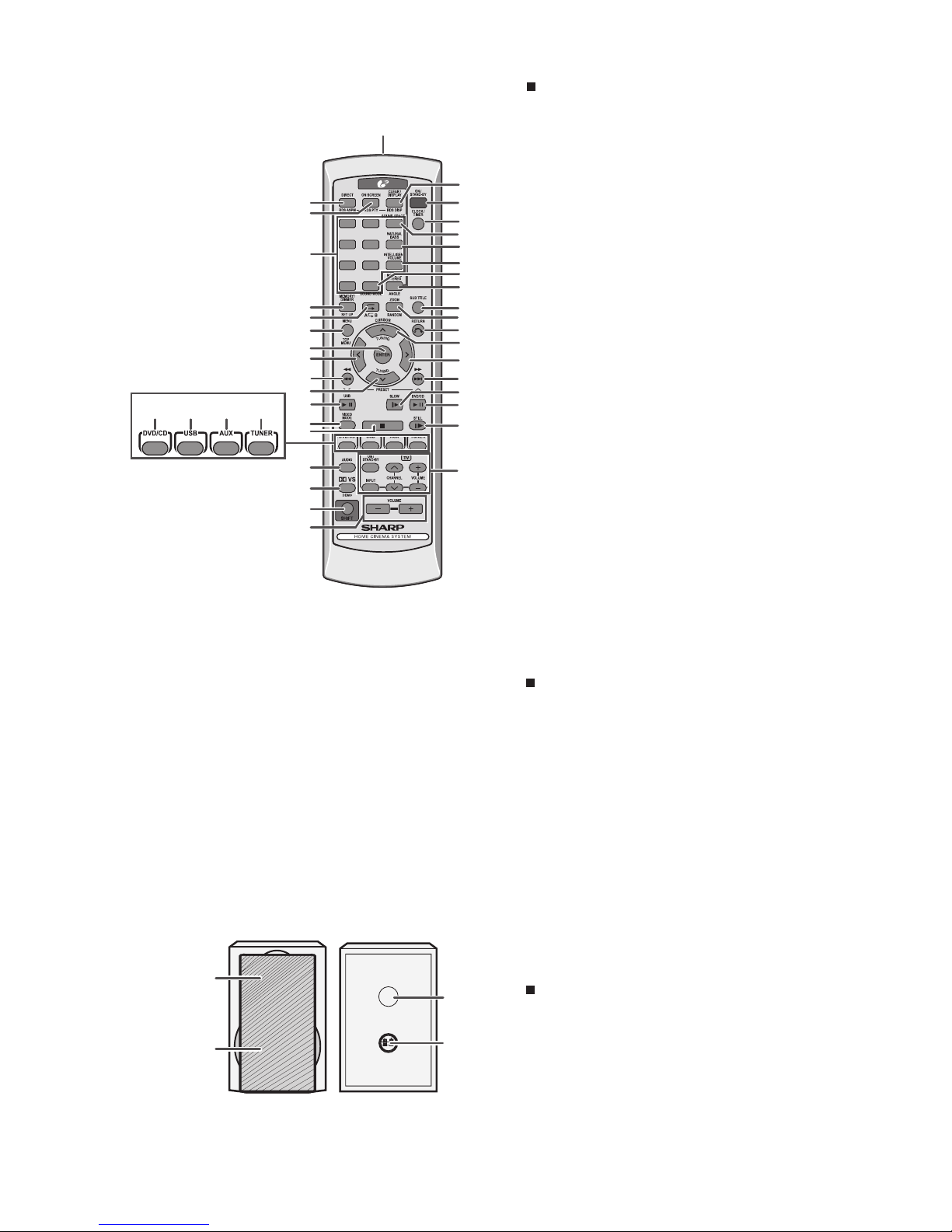
HT-DV30H
– 2
[3] Names Of Parts
Front panel
1. CD Compartment
2. On/Stand-by Button
3. Timer Indicator
4. DVD/CD/USB Play/Pause Button
5. Disc or USB Stop Button
6. Function Button
7. Remote Sensor
8. Headphone Socket
9. Disc Open/Close Button
10. Volume Control
11. USB Terminal
1. Chapter Indicator
2. Title Indicator
3. Folder Indicator
4. MP3 Indicator
5. WMA Indicator
6. RDS Indicator
7. Traffic Announcement Indicator
8. Dynamic PTY Indicator
9. Traffic Programme Indicator
10. Total Indicator
11. Sleep Indicator
12. Timer Play Indicator
13. Daily Timer Indicator
14. FM Stereo Mode Indicator
15. FM Stereo Receiving Indicator
16. Dolby Digital Signal Indicator
17. DTS Indicator
18. Dolby Virtual Speaker Indicator
19. Dolby Pro Logic II Indicator
20. Mono to Stereo Indicator
21. Intelligent Volume Indicator
22. Natural Bass Indicator
23. Sound Space Indicator
24. Memory Indicator
25. Disc or USB Pause Indicator
26. Disc or USB Play Indicator
27. Disc or USB Repeat Indicator
1. HDMI Socket
2. FM 75 Ohms Aerial Socket
3. Auxiliary Input Sockets
4. SUBWOOFER PRE OUT
5. Front Speaker Terminals
6. Cooling Fan
7. Optical Digital Input 1 Socket
8. Optical Digital Input 2 Socket
9. Video Output Socket
10. S-Video Output Socket
11. Component Video Out Sockets
12. SCART Output Socket (Audio + Video)
13. AC Power Lead
Rear panel
Display
1
2
310
9
111
8
DOOR OPEN
1
2
3
9
10
11
12
13
654 87
MP3
WMA
RDS TA PTYI TP
TOTAL
DAILY
MTS
MEMORY
MHz
A1 B
IVC NB SS
DIGITAL
VS PL
ST
FOLDTITLE
CHAP
SLEEP
1 2 3 4 56 7 8 9 10 11
26
25 27
12
DAILY
DIGITAL
VS PL
ST
13
18 19
16 17
14 15
MTS
MEMORY
IVC NB SS
20 21 22 23
24
4567
1 – 2

HT-DV30H
–2
Remote control
1. Remote Control Transmitter
2. DVD Direct Button
3. DVD On Screen Button
4. Direct Search Buttons
5. Memory or Dimmer Button
6.DVD/CD/MP3/WMA Repeat Button
7. Menu Button
8. Enter Button
9. Cursor Left Button
10. DVD Chapter Skip/DVD/MP3/WMA Fast Reverse/CD/
MP3/WMA Track Down/Tuner Preset Down and Time
Down Button
11. Tuning Down or Cursor Down Button
12. USB Play or Pause Button
13. Video Mode Button
14. DVD/CD/MP3/WMA/Stop Button
15. DVD/CD/MP3/WMA Button
16. USB Button
17. Auxiliary Button
18. Tuner Button
19. Audio Button
20. Dolby Virtual Speaker Button
21. Shift Button
22. Volume Up or Down Buttons
23. Clear or Display Button
24. On/Stand-by Button
25. Clock or Timer Button
30. DVD Angle Button
31. DVD Subtitle Button
32. DVD Zoom Button
33. Return Button
34. Tuning Up or Cursor Up Button
35. Cursor Right Button
36. DVD Chapter Skip/DVD/MP3/WMA Fast Forward/CD/
MP3/WMA Track Up/Tuner Preset Up and Time Up Button
37. DVD Slow Button
38. DVD/CD/MP3/WMA Play or Pause Button
39. DVD/CD/MP3/WMA Still Button
40. TV Operation Buttons
Remote control with shift button
2. RDS ASPM Button
3. RDS PTY Button
5. Set Up Button
6. A-B Repeat Button
7. Top Menu Button
20. Demo Button
23. RDS DISP Button
26. Sound Space Button
27. Natural Bass Button
28. Intelligent Volume Button
29. Sound Mode Button
30. Mono to Stereo Button
32. Random Button
Speaker system
1. Tweeter
2. Woofer
3. Bass Reflex Duct
4. Speaker Terminals
1
2
3
4
1 2 3
4 5 6
7 8 9
+100
1
23
24
25
26
27
28
29
30
31
32
33
34
35
36
2
3
4
5
6
7
8
9
10
11
12
13
14
19
20
21
22
15 38
39
40
16 17 18
37
1 – 3

HT-DV30H
2 – 1
CD-ES700/CD-ES77CD-ES700/CD-ES77Service ManualCD-ES700/CD-ES77MarketE
CHAPTER 2. ADJUSTMENTS
[1] Servo Section
• Adjustment
Since this DVD system incorporates the following
automatic adjustment functions, readjustment is
not needed when replacing the pickup. Therefore,
different PWBs and pickups can be combined
freely. Each time a disc is changed, these
adjustments are performed automatically.
Therefore, playback of each disc can be performed
under optimum conditions.
Items adjusted automatically
1) Offset adjustment (The offset voltage between the
head amplifier output and the VREF reference
voltage is compensated inside the IC.)
* Focus offset adjustment
* Tracking offset adjustment
2) Tracking balance adjustment
3) Gain adjustment (The gain is compensated inside
the IC so that the loop gain at the gain crossover
frequency will be 0 dB.)
* Focus gain adjustment
* Tracking gain adjustment

HT-DV30H
2 – 2
[2] Test Mode
1.Test Mode Functions
1.1.Entering the Test Mode
While holding down both the ■ button and the ON/STAND-BY button of the main unit from the AC Supply Off state,
turn the AC Supply ON to enter the Test Menu Mode.
[ ■] + [ ON/STAND-BY ] [ AC ON ]
1.2.TEST Mode Processing
* When entering the TEST Mode, the ROM version are displayed as follows.
* System micom version on the FL display upper row : HDH**** ( **** : Version No )
* DVD Firmware version on the FL display lower row : SRCV** ( ** : Version No )
1.3.TEST Mode button
* Press direct designation button or turn VOL Jog during the version display to enter the specified TEST Mode as
shown below.
* exit test mode by ON/STAND-BY key during micom version display
1.4.Canceling TEST Mode
Press the ON / STAND-BY button in each TEST Mode.
TEST MODE TEST MODE PROCEDURE TO ENTER
TEST 15 DVD TEST Turn VOL Jog to select "DVD TEST" during version
display, then press [STOP] key to enter.
TEST 16 FIRMWARE UPDATE TEST Direct press [PLAY] key during version display.

HT-DV30H
2 – 3
[3] DVD Test Mode
[STEP 1]
[STEP 2]
[STEP 3]
[STEP 4]
[STEP 5]
[STEP 6]
[STEP 7]
[STEP 8]
[STEP 9]
[STEP 10]
[STEP 11]
At testmode menu, select
"DVD TEST MODE" by
turning VOL Jog UP and Down
and press [STOP] key to enter
dvd test mode
In dvd test mode, DVD start up in cd mode
but no need to do disc reading process
Note 1:
Press [DVD/CD] key at remote control to
turn ON CD Laser
Press again [DVD/CD] key at remote
control, this time to turn ON DVD
Laser
"CD_LASER_ON" appear in unit
display
Press again [DVD/CD] key at remote
control, this time to turn OFF the
laser
Press ON/STAND-BY key to exit
the test mode.
EXIT the test mode
END
"DVD TEST", will appear in
unit display
"DVD_LASER ON" appear in unit
display
"LASER OFF" appear in unit
display

HT-DV30H
2 – 4
[4] DVD Firmware Update Test Mode
After enter testmode menu, press
[PLAY] key at main unit to select
"FW UPDATE TEST MODE" to
enter this mode
After ENTER key is pressed,
unit display at lower row will show
"_UPDATING_" blinking display
Press ENTER
key to start F/W upgrade.
After update process completed,
new firmware version will be
displayed in unit display lower row as
"FW_SRCV_ϠϠ"
END
Plug in USB device
User press [ON/STAND-BY]
key to exit this testmode
When enter firmware upgrade menu,
unit display at lower row change to
"FW_SRCV_ϠϠ" blinking at 2Hz
Note 2:
Make sure there is "DVDROM.bin" file inside the usb device
Note 3:
"_UPDATING_" blinking display means DVD
firmware upgrade is in progress.
During firmware upgrading is in progress, do not
POWER OFF the unit!
Note 1:
To enter testmode, during AC supply off
condition, whilst pressing down STOP key and
ON/STAND-BY key together, turn ON AC Supply.
" FW_UPDATE_ " will appear on upper row of
unit display and current firmware version DVD
will appear on lower row of unit display as "
FW_SRCV ** "

HT-DV30H
2 – 5
Amp abnormal detection and System PROTECTION display
In case amp abnormal detection or System PROTECTION had occurred, the unit will automatically enter to stand-by
mode and Timer indicator will flashing as below.
Example : In case of amp abnormal
Software RESET.
Function: - Software RESET ( Press Eject + ON / STAND-BY key while set at Standby mode ).
All the function condition will be initialize.
After display "CLEAR ALL", the unit will shows demo display.
BEFORE TRANSPORTING THE UNIT
The following process need to be taken after set tapering / parts replacement.
1. Press the ON / STAND-BY button to power on the unit.
2. Select DVD / CD function, then press [SHIFT]+[SETUP] key at remote control to enter DVD SETUP menu.
3. Use cursor up / down key to select DEFAULT, then press cursor RIGHT key to select "RESTORE".
4. While cursor is highlited at "RESTORE" press ENTER key.
5. After that select "EXIT SETUP" and press ENTER key.
6. Press the ON / STAND-BY button to enter standby mode.
7. While pressing down EJECT button, press the ON / STAND-BY button. "CLEAR ALL" will be display at FL.
8. Unplug the AC cord and the unit is ready for transporting.
Note:
Connect this unit to TV in order to view step no 1 ~ 5.
ON FLASHING ON ON FLASHING
TIMER
LED OFF NO. 1 OFF OFF NO. 3 OFF NO. 1 OFF
NO. 2 NO. 2
1 FRAME (REPEAT)
NO. 1 : System Protect
NO. 2 : Amp abnormal
NO. 3 : DVD +B Protect

HT-DV30H
-MEMO-

HT-DV30H
4 – 1
CHAPTER 4. DIAGRAM
[1] Main Block Diagrams
(TP1)
Figure 4-1: MAIN BLOCK DIAGRAM (1/2)

HT-DV30H
4 – 2
IC701
IXA161AW00 PR
PB
Y
S01
Figure 4-2: MAIN BLOCK DIAGRAM (2/2)

HT-DV30H
4 – 3
[2] DVD/CD Block Diagrams
204
203
201
196
198
199
194
221
219
218
211
IS42516400F
Figure 4-3: DVD/CD BLOCK DIAGRAM (1/2)

HT-DV30H
4 – 4
18
48
46
45
44
24
40, 41
2914
27,32
33
34
35
38
38
35
34
33
39
1551
52
2
Buffer
Amp
Buffer
Amp
Lch
S.W.
Rch
Power
Amp
MIX
LPF
VOL
NJU7391
(2/2)
FOR
SCART
SIGNAL
Analog
Signal
OPT 1
OPT 2
COAX
TO
SCART
23
Figure 4-4: DVD/CD BLOCK DIAGRAM (2/2)

HT-DV30H
4 – 5
[3] Power Block Diagrams
AC SUPPLY
220-240V ~ 50Hz
Figure 4-5: POWER BLOCK DIAGRAM (1/2)

HT-DV30H
4 – 6
DZ957
Q909
Figure 4-6: POWER BLOCK DIAGRAM (2/2)

HT-DV30H
5 – 1
CHAPTER 5.
CIRCUIT DESCRIPTION
[1] Waveform of CD / DVD Circuit
WF1
VIDEO OUT
WF2
S-VIDEO - Y OUTPUT
WF3
S-VIDEO OUT - C OUT
WF4
COMPONENT VIDEO OUT - Y Output
(Interlace mode)
WF5
COMPONENT VIDEO OUT - Y Output
WF6
COMPONENT VIDEO OUT - Pb/Cb Output
(P-Scan mode) (Interlace mode)
* NOTE:
WF1 ~ WF3 : Power On (stop) Mode.
MF4 ~ WF7 : DVD Test Disc TDV-540A.
(Colour Bar 75%)

HT-DV30H
5 – 2
WF7 COMPONENT VIDEO OUT - Pb/Cb Output WF8 COMPONENT VIDEO OUT - Pr/Cr Output
(P-Scan mode) (Interlace mode)
WF9 COMPONENT VIDEO OUT - Pr/Cr Output WF10 Audio Left
(P-Scan mode)
WF11 Audio Right WF12 RF Signal (CD)
WF13 RF Signal (DVD)
* Note:
WF8 ~ WF9 : DVD Test Disc TDV-540A
(Colour Bar 75%)
WF10 ~ WF11 : DVD/CD Test Disc 1KHz, 0db.
WF12 ~ WF13 : Nomal Disc

HT-DV30H
5 – 3
[2] Voltage
IC1 ( VHiSP8281AWU5 )
PIN
NO
VOLTAGE
(V)
PIN
NO
VOLTAGE
(V)
PIN
NO
VOLTAGE
(V)
PIN
NO
VOLTAGE
(V)
1 1.65 56 3.26 111 1.99 166 3.52
2 1.67 57 3.26 112 3.27 167 3.24
3 0.93 58 1.63 113 1.30 168 0.00
4 2.07 59 1.63 114 1.27 169 0.00
5 2.09 60 0.00 115 3.12 170 3.43
6 2.06 61 0.00 116 3.00 171 3.85
7 2.06 62 4.34 117 2.97 172 3.34
8 2.06 63 3.26 118 2.74 173 4.95
9 2.09 64 3.26 119 0.00 174 4.97
10 2.06 65 0.00 120 2.74 175 1.14
11 2.06 66 1.74 121 0.00 176 3.24
12 2.06 67 3.62 122 1.69 177 3.24
13 1.67 68 4.10 123 0.42 178 3.23
14 2.08 69 3.94 124 2.12 179 2.45
15 2.09 70 3.20 125 1.78 180 0.00
16 0.00 71 3.20 126 0.42 181 0.00
17 0.00 72 0.00 127 0.29 182 1.77
18 3.24 73 0.00 128 0.40 183 0.00
19 2.24 74 3.24 129 0.00 184 0.00
20 1.08 75 3.13 130 1.73 185 0.00
21 1.08 76 0.00 131 0.00 186 0.00
22 3.24 77 2.72 132 3.21 187 3.52
23 3.24 78 3.13 133 1.75 188 3.85
24 2.25 79 3.29 134 0.00 189 3.25
25 1.54 80 3.18 135 0.06 190 3.26
26 3.24 81 3.19 136 0.18 191 3.25
27 1.54 82 3.24 137 0.12 192 0.00
28 3.05 83 3.25 138 0.12 193 0.03
29 2.30 84 3.27 139 0.00 194 0.00
30 2.81 85 0.00 140 3.28 195 1.61
31 0.94 86 0.00 141 0.20 196 0.00
32 0.95 87 0.65 142 0.19 197 3.23
33 0.95 88 0.05 143 0.00 198 0.00
34 1.65 89 0.90 144 1.78 199 0.00
35 1.53 90 1.77 145 3.07 200 5.08
36 1.53 91 3.00 146 3.19 201 1.62
37 1.63 92 0.20 147 2.74 202 0.00
38 1.63 93 3.05 148 0.00 203 1.62
39 1.62 94 3.05 149 0.00 204 1.62
40 0.00 95 0.13 150 0.00 205 3.68
41 3.26 96 3.29 151 0.05 206 3.24
42 3.25 97 3.11 152 3.89 207 2.62
43 1.62 98 1.62 153 3.87 208 1.61
44 1.62 99 1.62 154 3.96 209 1.64
45 1.71 100 3.21 155 3.88 210 1.62
46 1.67 101 0.00 156 3.24 211 0.51
47 1.67 102 0.00 157 3.62 212 3.23
48 1.62 103 0.00 158 3.63 213 0.00
49 1.67 104 3.14 159 3.24 214 0.00
50 1.62 105 0.00 160 3.24 215 0.00
51 1.65 106 1.75 161 3.27 216 3.22
52 1.64 107 1.76 162 3.17 217 0.00
53 1.66 108 2.57 163 1.77 218 0.58
54 1.66 109 1.26 164 3.24 219 1.55
55 3.26 110 1.28 165 3.16 220 3.25
Other manuals for HT-DV30H
1
This manual suits for next models
1
Table of contents
Other Sharp Home Theater System manuals

Sharp
Sharp HT-X1 User manual

Sharp
Sharp HT-SB60 User manual

Sharp
Sharp HT-SBW182 User manual

Sharp
Sharp HT-DD5000 User manual

Sharp
Sharp HT-SL72 User manual

Sharp
Sharp HT-M750H User manual

Sharp
Sharp HT-DP3000 User manual

Sharp
Sharp HT-SL70 User manual

Sharp
Sharp HT-X1H User manual

Sharp
Sharp HT-SB60 User manual

Sharp
Sharp HT-SB600 User manual

Sharp
Sharp HT-DV30H User manual

Sharp
Sharp SD-AT100W User manual

Sharp
Sharp HT-SB60 User manual

Sharp
Sharp HT-CN400DVH User manual

Sharp
Sharp SBW800 User manual

Sharp
Sharp HT-SBW460 User manual

Sharp
Sharp HT-CN650DVW User manual

Sharp
Sharp AN-PR1000H User manual

Sharp
Sharp HT-SB140(MT) User manual