thermastor Quest PowerDry 4800D DRY 150 Pro LP Manual
Installation, Operation and Maintenance Instructions
– Read and Save These Instructions –
This manual is provided to acquaint you with
the 4800D so that installation, operation
and maintenance can proceed successfully.
Ultimate satisfaction depends on the quality
of installation and a thorough understanding
of this equipment. This unit is built around
tested engineering principles and has passed
a thorough inspection for quality of workman-
ship and function.
Installation, Operation and Maintenance Instructions
4201 Lien Rd. Phone 608-237-8400
Madison, WI 53704 Toll-Free 1-866-933-7486
www.QuestProtect.com sales@QuestProtect.com
– Read and Save These Instructions –
Specications subject to change without notice. TS-650/651
08/17
1
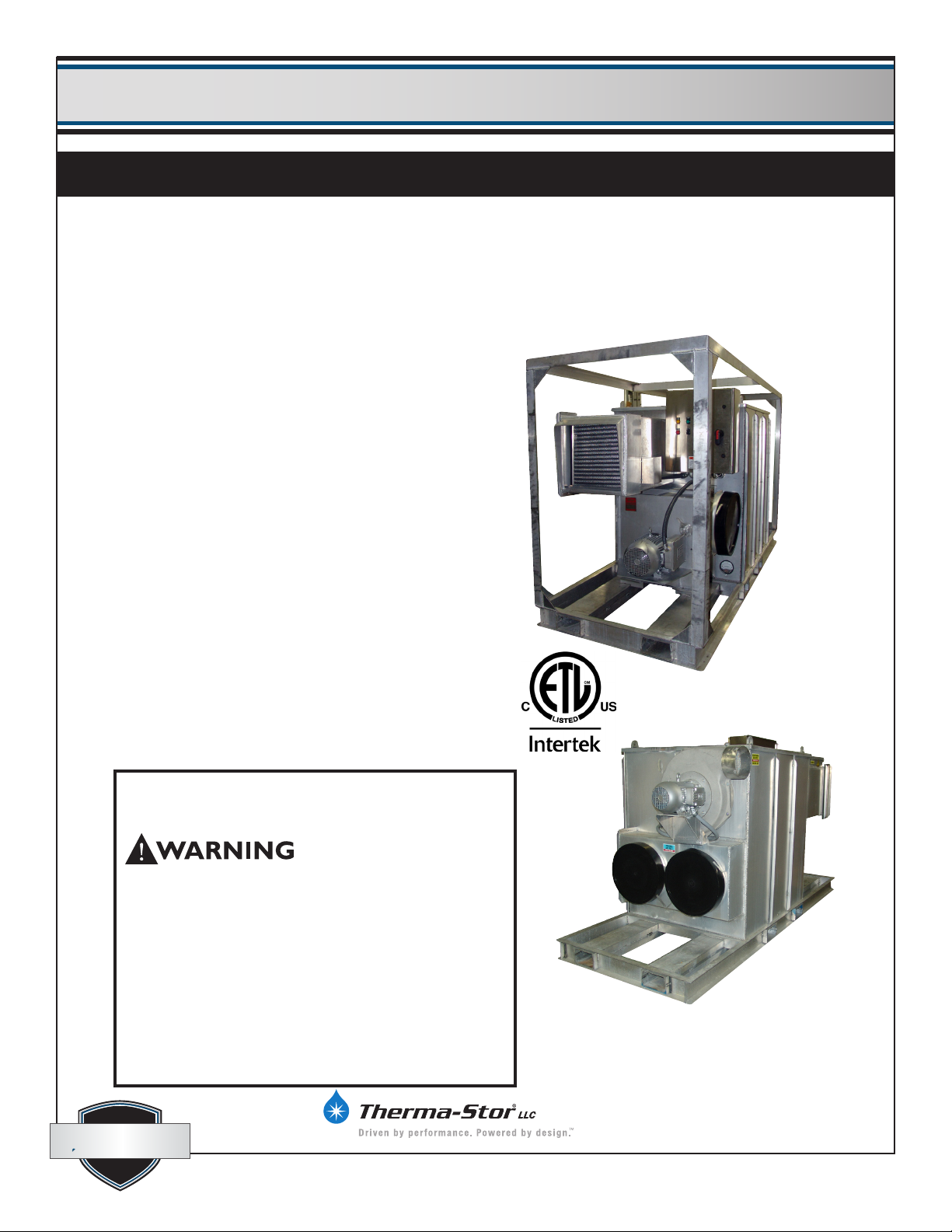
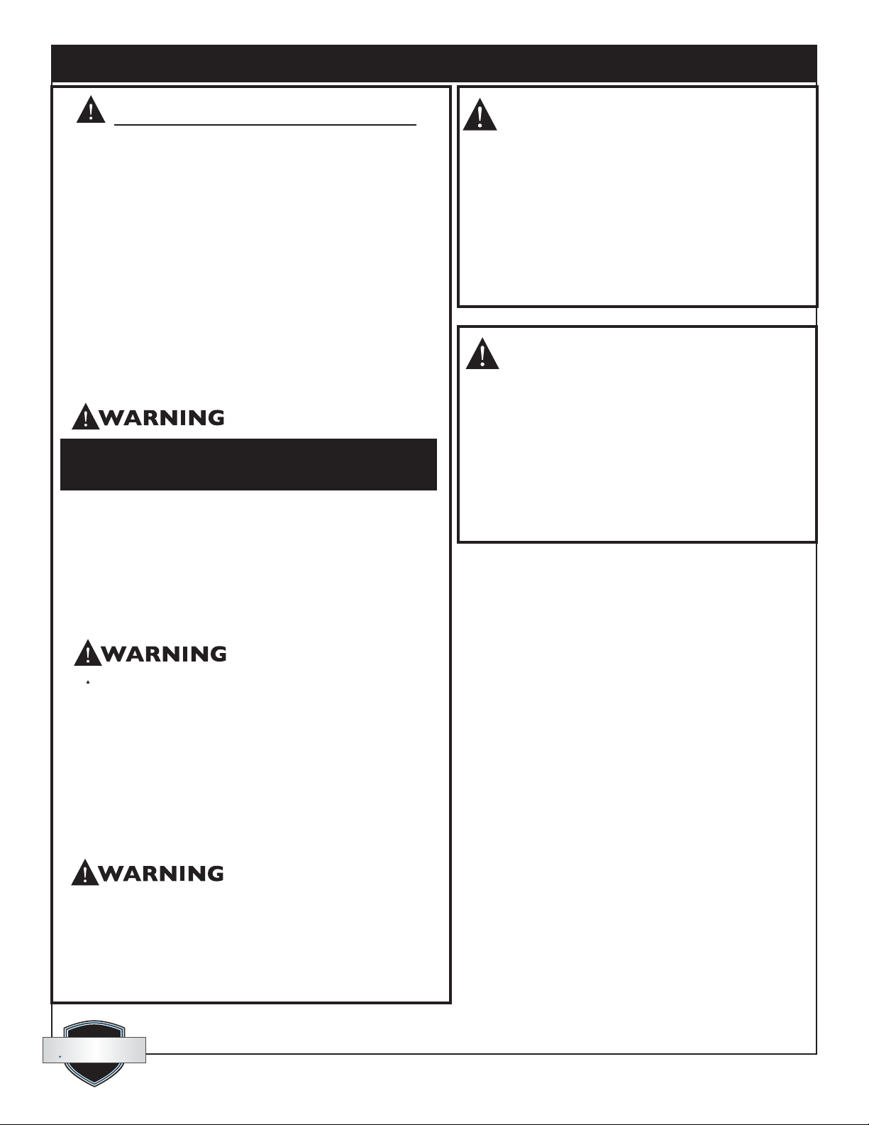
Quest PowerDry 4800D Pro LP/NG:
• 3032 Pints/day AHAM
• 4800 CFM process airow
• Dries in temperatures to 140°F
• Reaches dew points as low as -40°F
• 48”W x 120”L x 74”H
• 1600 lbs. (Standard machine weight only)
• 240 volt, 70 amp single phase
• Propane or Natural Gas Fired
Quest DRY150Quest PowerDry 4800D Pro LP/NG
Quest PowerDry 4800D
Pro P/N
(with Frame)
PN 4028204 Propane
PN 4030630 Nat Gas
Quest PowerDry 4800D
Pro P/N
(without Frame)
PN 4029194 Propane
PN 4030640 Nat Gas
FOR YOUR SAFETY: DO NOT store or use
gasoline or other ammable vapors and liquids in the
vicinity of this or any other appliance.
Improper installation, adjustment, alteration, service
or maintenance can cause injury or property damage.
Refer to this manual. For assistance or additional
information, call a qualied installer, service agency or
the gas supplier.
FOR YOUR SAFETY: If you smell gas: DO NOT
try to light any appliance. DO NOT touch any electrical
switch. IMMEDIATELY call your gas supplier from a
location away from the device. If the gas supplier cannot
be reached, call the re department.
quest
quest
quest
quest 1-866-933-7486
Quest PowerDry 4800D Pro P/N Installation, Operation and Maintenance Instructions
2
www.QuestProtect.com
sales@QuestProtect.com
GENERAL HAZARD WARNING
Failure to comply with the precautions and
instructions provided with this unit can result
in death, serious bodily injury and property loss
or damage from hazards of fire, explosion, burn,
asphyxiation, carbon monoxide poisoning, and/or
electrical shock.
Only persons who can understand and follow the
instructions should use or service this unit.
If you need assistance or unit information such
as an instruction manual, label, etc., contact a
qualified installer, service agency, gas supplier, or
the manufacturer.
Do NOT use this appliance if any part has been
under water. Immediately call a qualified service
technician to inspect the appliance and to replace
any part of the control system and any gas
control which has been under water.
Should overheating occur, or the gas supply fail
to shut off, shut off the manual gas valve to the
appliance before shutting off the electrical supply.
Installation must conform to applicable local codes and/
or the National Fuel Gas Code, ANSI Z223.1, the Standard
for the Storage and Handling of Liquefied Petroleum
Gasses, ANSI/NFPA 58 and the Natural Gas and Propane
Installation Code, CSA B149.1.
Other standards govern the use of fuel gases and heat
producing products in specic applications. Your local
authority can advise you about these.
FIRE, BURN, INHALATION, AND
EXPLOSION HAZARD.
Keep solid combustibles, such as building materials,
paper, or cardboard, a safe distance away from the
unit as recommended by the instructions. Never use
the unit in spaces which do or may contain volatile or
airborne combustibles, or products such as gasoline,
solvents, paint thinner, dust particles or unknown
chemicals.
MISES EN GARDE GENERALES
Le non-respect des mises en garde et des instructions fournies avec
ce radiateur peut entrainer la mort, de graves blessures et des pertes
materielles ou des dommages a la propriete resultant d’un incendie,
d’une explosion, de brulures, d’asphyxie, d’empoisonnement au
monoxyde, de carbone et/ou d’un choc electique.
Seules les personnes aptes a comprendre et a suivre les instructions
devraient se servir de ce radiateur ou le reparer.
Si vous avez besoin d’aide ou d’informations concernant ce radiateur
ou le reparer.
Avertissement
Risque d’incendie, de brulures, d’inhalation et d’explosion.
Garder les combustibles solides, tels les materiaux de
construction, le papier et le carton, a bonne distance de ce
radiateur, comme il est recommande dans les instructions.
ne jamais utiliser cet appareil dans des endroits qui
contiennent ou pourraient contenir des combustibles
volatiles ou en suspension dans l’air tels l’essence, les
solvants, les diluants pour peinture, les particules de
poussieres ou des produits chemiques inconnus.

Quest PowerDry 4800D Pro P/N Installation, Operation and Maintenance Instructions
3
www.QuestProtect.com
sales@QuestProtect.com
quest
quest 1-866-933-7486
Table of Contents
Introduction .......................................................1
1. Specications ..............................................4
2. Operation ...................................................4
2.1 How the Quest Dry
PowerDry 4800D Pro P/N Works ...............5
3. Installation ..................................................5
3.1 Inspection .............................................5
3.2 Location ................................................6
3.3 Set-Up ..................................................6
3.4 Ducting .................................................6
3.5 Avoiding Secondary damage .................7
3.6 Electrical Requirements .........................7
4. Operation Instructions.................................8
4.1 Connect and Start-Up Procedure ...........8
4.2 Cool Down ...........................................8
4.3 Shut Down and Disconnect Procedure..8
5. Control Panel ..............................................9
5.1 Main Disconnect ..................................9
5.2 Standby Light ........................................9
5.3 Selector Switch .....................................9
5.4 Alarm (Light and Horn) .........................9
5.5 Hour Meter .........................................10
6. Maintenance .............................................10
6.1 General Maintenance..........................10
6.2 Cabinet ...............................................10
6.3 Filter ...................................................10
6.4 Blower and Motor ...............................10
6.5 Drive Motor ........................................11
6.6 Rotor Drive Chain ...............................11
6.7 Seals ...................................................11
6.8 Desiccant Media .................................11
7. Wiring Diagram ........................................12
8. Trouble Shooting .......................................16
9. Service Parts ..............................................17
Warranty ...................................................18
Serial No.__________________________________
Purchase Date_____________________________
Dealer’s Name_____________________________
Read the operation and maintenance instructions
carefully before using this unit. Proper
adherence to these instructions is essential
to obtain maximum benet from your Quest
PowerDry 4800D Pro P/N.

quest
quest 1-866-933-7486
Quest PowerDry 4800D Pro P/N Installation, Operation and Maintenance Instructions
4
www.QuestProtect.com
sales@QuestProtect.com
Quest PowerDry 4800D Pro LP/NG Installation, Operation and Maintenance Instructions
4
1. Specications
Part No. 4028204 Propane (with cage)
4030630 Nat Gas (with cage)
Part No. 4029194 Propane (without cage)
4030640 Nat Gas (without cage)
Power 240 volt, 70 amps single phase
Water 3032 pints/day @ AHAM
Removal
Blower 4800 CFM Process Air Flow
2000 CFM Reactivation Air Flow
Operating -10ºF to 140ºF
Range
Filters Process lter size: (2) 20” x 20” x 2”
Reactivation lter size: (1) 20” x 20” x 2”
Duct Options Process inlet/outlet - 18” Heavy Duty PVC minimum, 20” Heavy Duty PVC recommended
Reactivation - 18” Heavy Duty PVC minimum, 20” Heavy Duty PVC recommended
Warranty 1 Year 100% Parts & Labor
Dimensions
Machine only With Cage
Width 48” 48”
Height 66” 72”
Length 120” 120”
Weight 1550 lb 1675 lb
Accessories
4028364 18” x 25’, 6” Pitch, Heavy Duty PVC/Polyester Duct
4029256 18” Lay Flat Duct
4035579 20” x 25’, 4” Pitch, Heavy Duty PVC/Polyester Duct
4027327 External Temperature control
4020175 External Dehumidistat
Air Filter Replacement
4028635 20” x 20” x 2” Filter (3 per unit)
2. Operation
The function of the dehumidier is to remove moisture (in the vapor state) from an air stream. This is
accomplished by exposing the air to an adsorbing media (desiccant) in a sealed air stream (process).
After the desiccant has adsorbed moisture, it is exposed to a second air stream at an elevated temperature
(reactivation). This causes the moisture to be driven out of the desiccant preparing it for more moisture
Quest PowerDry 4800D Pro P/N Installation, Operation and Maintenance Instructions
5
www.QuestProtect.com
sales@QuestProtect.com
quest
quest 1-866-933-7486
Quest PowerDry 4800D Pro LP/NG Installation, Operation and Maintenance Instructions
5
adsorption. This process is done on a
continuous basis, providing a constant drying
process. The two air streams (process and
reactivation) are separated by seals, which
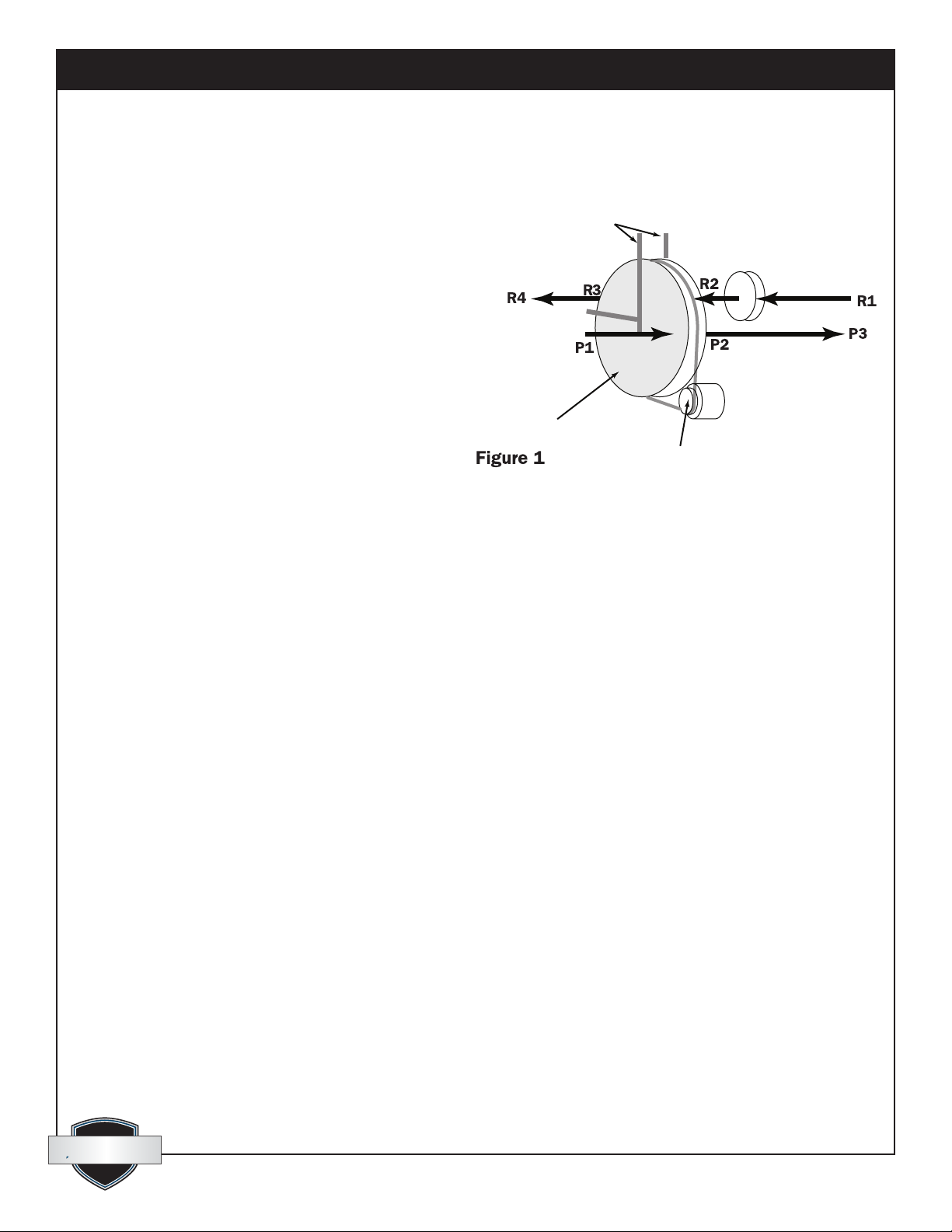
contact the desiccant media. Figure 1 illustrates
the relationship of the seals and airow pattern.
The dehumidier is designed with the two air
streams owing in opposite directions (counter
ow) thereby maximizing the energy efciency
of the equipment.
2.1 How the Quest PowerDry 4800D
Pro P/N Works
The Quest PowerDry 4800D Pro P/N has
two separate air streams that run through it –
Process and Reactivation (Fig. 1).
Process Air Stream:
P1 – 4800 CFM of air enters the machine (Process Air Inlet) and...
P2 – ...water vapor from incoming air is deposited (adsorbed) on the desiccant wheel.
P3 – 4800 CFM of dry air exits the machine (Process Air Outlet).
Reactivation Air Stream:
R1 – 2000 CFM of air enters the machine (Reactivation Air Inlet) and...
R2 – passes over the heater coils.
R3 – Water vapor is picked up (desorbed) from the desiccant wheel by the hot air and...
R4 – ... 2000 CFM of wet air exits the machine (Reactivation Air Outlet).
3 Installation
Proper installation is critical to the performance of the Quest PowerDry 4800D Pro P/N. Follow the
guidelines below to maximize service life and performance.
3.1 Inspection
Thoroughly inspect the machine to insure no damage has occurred during shipping or on the job site.
The hose assembly shall be visually inspected prior to each use of the heater. If it is evident there is excessive
abrasion or wear, or the hose is cut, it must be replaced prior to the heater being put into operation. The
replacement hose assembly part is listed in the service parts list.
Cabinet Divider
and Seals
Reactivation Air Outlet
Process Air Inlet
Heater
Principle of Operation
Process Air Outlet
Desiccant Wheel
Desiccant Wheel
Drive and Chain
Reactivation Air Inlet

quest
quest 1-866-933-7486
Quest PowerDry 4800D Pro P/N Installation, Operation and Maintenance Instructions
6
www.QuestProtect.com
sales@QuestProtect.com
3.2 Location
Note the following precautions when locating the Quest PowerDry 4800D Pro P/N:
The Quest PowerDry 4800D Pro P/N must be located outdoors with reactivation outlet pointed away
from open windows or building fresh air inlets. Position unit for shortest, straightest duct run to structure.
Provisions for adequate combustion and ventilation air must be provided in accordance with section 5.3 of
the National Fuel Gas Code ANSI Z223.1.
Always ensure the Quest PowerDry 4800D Pro P/N is located with the reactivation outlet pointed such that
the reactivation air exhausts to the atmosphere in an unoccupied area and can NOT be drawn into any
nearby structure. Do not exhaust reactivation air across walkways or towards buildings, openable windows,
or building openings. Do not allow the reactivation outlet to become obstructed by snow, construction
debris, etc. Maintain a minimum 4’ clearance around electric and gas meters, regulators, and relief
equipment. Locate device a minimum of 10’ from combustible constructions. Be aware that reactivation
air contains ue gasses that, over time, can degrade some building materials. Do not connect device to a
chimney ue serving a separate appliance designed to burn solid fuel.
Do not direct process or reactivation air streams toward any Propane-gas container within 20’ (6m).
3.3 Set-Up
When conditions warrant the use of a desiccant dehumidier, use one of the setups described below to
achieve efcient drying, while avoiding secondary damage. Review Section 2.1 to understand the desiccant
drying process. Always ensure that the Reactivation Outlet duct is vented to the outdoors to minimize the
possibility of secondary damage.
Neutral Pressure Setup
Many drying applications require neutral pressure operation. In this setup, the Process Air Inlet pulls air
from the affected area (drying chamber) and returns dried, processed air to the affected area via the Process
Air Outlet.
Positive Pressure Setup
For Positive Pressure operation, the Process Air Inlet pulls air from outside the drying chamber, while the
Process Air Outlet is ducted into the chamber.
3.4 Ducting
The duct requirements of the Quest PowerDry 4800D Pro P/N are much more critical than those of
refrigerant-based dehumidiers. ALL SUPPLY AND RETURN AIR DUCTING FOR THE Quest PowerDry
4800D Pro P/N MUST BE AIR AND VAPOR TIGHT. This is extremely important for proper performance.
Ensure that reactivation discharge air does not enter the process or reactivation inlets.
Using excess duct length signicantly reduces air ow volume through duct. This is true in any application. If
the job at hand needs a short length of duct, cut a section to the appropriate length. If air ow is restricted by
excess length, performance will suffer. The same can be said of excess bends in the ducting.
Multiple duct sizes are used on the Quest PowerDry 4800D Pro P/N (see below). All ducting materials are
available from Therma-Stor LLC
(see accessories list in Section 1).

Quest PowerDry 4800D Pro P/N Installation, Operation and Maintenance Instructions
7
www.QuestProtect.com
sales@QuestProtect.com
quest
quest 1-866-933-7486
Process inlet: 18” ex duct.
To attach ex ducts to the process air intake, push the wire of the rst few loops beyond the 2 holes in the
duct collar. Push the metal rod through the duct and duct collar piercing the duct in two places. Tape or a
hose clamp can be used to create an airtight seal. Alternatively, the duct wire can be pushed past the weld
beads on the duct collar and the duct can be secured with hose clamps or ratcheting straps. If using only
one inlet connection, the other can be left closed.
Process outlet: 18” ex or lay at plastic duct.
To attach ex ducts to the process air outlet, push the wire of the rst few loops beyond the 2 holes in the
duct collar. Push the metal rod through the duct and duct collar piercing the duct in two places. Tape or a
hose clamp can be used to create an airtight seal. Alternatively, the duct wire can be pushed past the weld
beads on the duct collar and the duct can be secured with hose clamps or ratcheting straps.
When using 18” lay at ducting, slip over the outlet collar and zip-tie or duct tape in place.
Reactivation outlet: 10” ex duct or lay at.
To attach ex duct to the reactivation air outlet, push the wire of the rst couple of loops beyond the weld
beads on an outlet collar. Secure with hose clamp.
3.5 Avoiding Secondary Damage
The Quest PowerDry 4800D Pro P/N is a powerful tool capable of removing a great deal of water from
most environments. Care must be taken to avoid secondary damage of over-drying and or unexpected
condensation.
The Quest PowerDry 4800D Pro P/N removes vapor water from the incoming process air stream and
transfers it to the outgoing reactivation air stream. The reactivation exhaust air is hot and wet.
Take care to prevent the reactivation exhaust air stream from causing secondary damage due to
condensation. Always ensure the Quest PowerDry 4800D Pro P/N is located with the reactivation outlet
pointed such that reactivation air will NOT be drawn back into the structure.
The Quest PowerDry 4800D Pro P/N does not produce liquid water internal to the machine. There is no
condensate pump and no drain hose.
The Quest PowerDry 4800D Pro P/N desiccant dehumidier will continue to remove water from already dry,
cold air. It is possible to over-dry objects and or structures.
Care must be taken to avoid secondary damage due to over-drying.
3.6 Electrical Requirements
A 240 volt, single phase power source is required to operate the Quest PowerDry 4800D Pro P/N.
All local and state codes must be strictly adhered to and good electrical practices should be followed to
achieve the best installation possible. The Quest PowerDry 4800D Pro P/N must be properly wired to an
adequate power source. The electrical grounding of the appliance shall be in compliance with the National
Electrical Code, ANSI/NFPA 70, or the CSA C22.1, Canadian Electrical Code, Part I. Serious damage to the
motors and controls can occur if incorrect voltage is applied.
(See Electrical Schematic drawing in the back of this manual for internal wiring.)

quest
quest 1-866-933-7486
Quest PowerDry 4800D Pro P/N Installation, Operation and Maintenance Instructions
8
www.QuestProtect.com
sales@QuestProtect.com
4 Operating Instructions
Refer to the Operating Instructions label located next to the control panel of your Quest PowerDry 4800D
Pro P/N.
User-supplied power cord, cord grip, and branch protection appropriate for the electrical load must be
supplied. See device for FLA rating.
The Quest PowerDry 4800D Pro P/N dehumidier comes complete and ready for operation. All that is
required is to provide the proper power source, propane or natural gas supply, and duct connections
(described above).
4.1 Connect and Start-Up Procedure
1. STOP! Read the safety information on unit label.
2. Turn off all electric to this appliance - Selector Switch turned to STAND BY position. Main Disconnect
turned to OFF position.
3. Connect gas source.
• Propane: Connect propane gas source (5-20 psig) to hose attached to the regulator (located next to
the process blower, below reactivation inlet duct).
• Natural gas: Connect natural gas source (4-11” water column) to hose located on reacivation inlet
duct.
4. Open gas supply shut off valve.
5. Open appliance shut off valve.
6. Energize power source and turn Main Disconnect switch to ON.
7. Turn Selector switch to RUN.
8. Set process damper to obtain a maximum of 1.5” water column pressure as read on pressure gauge.
9. If the appliance will not operate, follow the instructions “To Turn Off Gas To Appliance” and call your
service technician or gas supplier.
4.2 Cool Down
1. Set Selector Switch to OFF.
2. COOL DOWN light will come on for 5 minutes.
3. When COOL DOWN light is off, Main Disconnect can be switched to OFF.
Failure to follow COOL DOWN PROCEDURE may result in damage to unit due to overheating. ALWAYS
follow COOL DOWN PROCEDURE before shutting unit down.
4.3 Shut Down & Disconnect Procedure
1. Verify COOL DOWN light is not illuminated and cool down procedure has been followed.
2. Close appliance shut off valve.

Quest PowerDry 4800D Pro P/N Installation, Operation and Maintenance Instructions
9
www.QuestProtect.com
sales@QuestProtect.com
quest
quest 1-866-933-7486
3. Close gas supply shut off valve.
4. Turn main disconnect switch to OFF.
5. Disengage power source.
6. Lock out power source.
7. Disconnect power cable.
8. Disconnect propane or natural gas source.
5 Control Panel
5.1 Main Disconnect
The main disconnect switches power from the source to the panel. Power must be disconnected at the
source prior to accessing control panel. Access to the control panel with power applied is ONLY by
qualied service personnel with the appropriate personal protective equipment Power is present up to
disconnect even in OFF position. Disconnect power at the source before opening panel.
5.2 Standby Light
The STANDBY indicator lamp illuminates to indicate that power is supplied to the control panel.
5.3 Selector Switch
When the selector switch is moved to the “RUN” position, the Quest PowerDry 4800D Pro P/N starts
dehumidifying. The machine will continue to dehumidify in all conditions until the power is turned off.
No dehumidistat is provided to monitor process inlet air condition (see over-dry warning section 3.5). An
external control (dehumidistat, thermostat or other contact) can be wired in place of the jumper across
terminals 100 and 3070. The external control must be designed to operate a 24 VAC circuit.
5.4 Alarm (Light and Horn)
The alarm indicator lamp illuminates (and horn sounds) to indicate that a fault condition exists. All ashing
faults ash for only 5 minutes after the fault occurs:
• No ash - An immediate alarm sounds after turning the unit on. This can be due to any pressure switch
being closed on start-up.
• 1 ash - Combustion Blower fault. Blower is not developing enough pressure differential (airow) to
support proper combustion.
• 2 ashes - Differential pressure between reactivation and process ducts too great. May be indicative of
blocked process inlet ducting.
• 3 ashes - Failure to ignite after 3 trials for ignition. Check gas supply. Ignitor failure may also produce
this fault.
• 4 ashes - Reactivation or process blower motor overload relay tripped.
• 5 ashes - High reactivation temperature. Temperature approaching the desiccant wheel may be
in excess of 325°F. Air ow through the reactivation section may be restricted. Ensure proper gas is
supplied to the unit.
An external alarm can be wired to relay output terminals 4440 and 4442. Relay contacts are rated 5A
resistive/2A inductive at 12/24 V AC/DC, 5A resistive/3A inductive at 115/120/230/240 VAC

quest
quest 1-866-933-7486
Quest PowerDry 4800D Pro P/N Installation, Operation and Maintenance Instructions
10
www.QuestProtect.com
sales@QuestProtect.com
5.5 Hour Meter
The hour meter will run whenever the Quest PowerDry 4800D Pro P/N is operating. This hour meter
measures the cumulative time of operation in one-tenth hour increments. This meter is often used to verify
hours on a job or to schedule maintenance.
6 Maintenance
6.1 General Maintenance
A denitive time schedule should be established for inspecting all rotating parts and components. Inspection
requirements depend on the frequency of operation, transport, and operating conditions. Periodically check
the condition of the air lter, rotating parts, and fasteners to ensure they are secure and in proper working
order. Periodically check airow to make sure there are no obstructions to airow in outlet or inlet ductwork.
Recommended minimum inspections:
• Upon installation
• After 1 week of operation.
• Annually thereafter or upon loss of performance.
6.2 Cabinet
Disconnect power before removing access panels.
Remove panel fasteners and panels from unit to access internal components. The condition of the cabinet
gaskets should be observed during inspection and servicing to insure a good seal. Any leaks must be sealed
and panels securely fastened for proper dehumidier operation.
6.3 Air Filters
The maintenance interval for the lter depends directly on the cleanliness of the air entering the
dehumidier. It is suggested that a program be established to assure that the lters are replaced or cleaned
prior to becoming clogged to the point they create a system problem.
Three aluminum (20”x20”x2”) air lters must be checked regularly. Two lters are located near the process
air inlet. The other one is located near the reactivation air inlet.
Wash the lters with fresh water. Clean the lter from the downstream side, forcing debris toward the lter
inlet. Dry the lters completely before installing them in unit. Replacement lters can be ordered from the
factory or purchased locally if available.
DO NOT operate the unit without the lters or with less effective lters as the desiccant wheel inside the
unit will become clogged and require disassembly to clean.
6.4 Blower and Motor
Blower and motor bearings are permanently lubricated and do not require maintenance. Blower wheel
- inspect wheel blades for accumulation of dust and dirt. Clean thoroughly with compressed air and or
vacuum. The wheel should not strike the housing or the inlet ring. Make sure wheel is rotating in the proper
direction.

Quest PowerDry 4800D Pro P/N Installation, Operation and Maintenance Instructions
11
www.QuestProtect.com
sales@QuestProtect.com
quest
quest 1-866-933-7486
6.5 Drive Motor
The media drive motor is permanently lubricated and requires no maintenance.
6.6 Rotor Drive Chain
A spring loaded tensioner keeps the chain sufciently tensioned. Check the chain for signs of excessive
wear. Replace as necessary. If additional tension is required, simply tighten the nuts on the tension springs as
required.
6.7 Seals
High temperature seals separate the process and reactivation compartments. Normally, the seals will not
require service or replacement. However, should damage occur, or if poor performance as the result of an
air leak is suspected, the following inspection must be performed to determine whether the seals should be
replaced:
Inspection:
1) Turn the unit off and remove the access covers.
2) Visually inspect for gaps between the desiccant media
and the seals.
3) If signicant gaps, wear, or damage are observed,
the seal needs to be replaced.
6.8 Desiccant Media
The silica gel desiccant media supplied with the dehumidier will last indenitely under ideal conditions.
Due to the nature of desiccants they make very good lters. The life of the desiccant is directly related to the
airborne contaminates passed through it. Atmospheric contaminants, exposure to acidic gases/or air streams,
and contact with petroleum based airborne particles can reduce the efciency of the desiccant media.
The preferred method of cleaning is to blow dust out with compressed air. Proper ltration and preventing
contact with chemicals will greatly improve the life of the desiccant. Inspect the face of the media to see that
no surface damage has occurred. If damage is noticed, please contact Therma-Stor at 1-800-533-7533 x8459
for assistance. The rotor should turn smoothly upon the shaft, if not check the support bearings.
Servicing the Quest PowerDry 4800D Pro P/N with its high voltage circuitry presents a health hazard
which could result in death, serious bodily injury, and/or property damage. Only qualied service people
should service this unit.
ELECTRICAL SHOCK HAZARD: Electrical power must be present to perform some tests; these tests should
be performed only by a qualied service person.

quest
quest 1-866-933-7486
Quest PowerDry 4800D Pro P/N Installation, Operation and Maintenance Instructions
12
www.QuestProtect.com
sales@QuestProtect.com
STAND BY
STAND
BY
RUN
STAND
BY
STAND
BY
RUN
3440
200
200
3090
3110
3130
3420
200
3150
4380
4440
4442
GND
GND
GND
200
100
100
100
100
1
200
3210
----
S1
S2
1
100
3070
4060

Quest PowerDry 4800D Pro P/N Installation, Operation and Maintenance Instructions
13
www.QuestProtect.com
sales@QuestProtect.com
quest
quest 1-866-933-7486

quest
quest 1-866-933-7486
Quest PowerDry 4800D Pro P/N Installation, Operation and Maintenance Instructions
14
www.QuestProtect.com
sales@QuestProtect.com
3110
3170
3150
3130
3190
MAIN CHASIS
24VAC INPUTS/RELAY OUTPUTS
230RCO
FROM PREVIOUS PAGE
FROM PREVIOUS PAGE
NEUTRAL24VAC
200
100
START/STOP
3072
3090
DEHUMIDISTAT
100
COMBUSTION BLOWER
PRESSURE SWITCH (PS1)
100
REACTIVATION BLOWER
PRESSURE SWITCH (PS2)
100
HIGH TEMPERATURE
OVERLOAD RELAY
OVERLOAD RELAY
FLAME VERIFICATION
100
3380
3420
3440
230RCO REACTIVATION BLOWER MOTOR
200
RMS
200
200
200
100
PROCESS BLOWER MOTOR
PMS
DESSICANT MOTOR
120VAC 1/50HP 0.33AMPS
RUN PILOT LAMP
GREEN
OX
ONOFF
DEHUMIDISTAT
H
P
PS1
SYSTEM
P
PS2
100
T
TS1
SWITCH (TS1)
100 OLR-R
100 OLR-P
REACTIVATION BLOWER MOTOR
PROCESS BLOWER MOTOR
RMS
3400
PMS
3382
3402
M
120VAC
1
G
RUN
M
200
HOUR METER
120VAC
3210
1
FROM FENWALL
MV1
100
REMOVE YELLOW JUMPER
TO USE OPTIONAL
EXTERNAL DEHUMIDISTAT
3070
200 COMBUSTION BLOWER
120VAC 107W 0.9AMPS
HM
CONTINUED NEXT PAGE CONTINUED NEXT PAGE
YELLOW
I3
I8
I7
I6
I5
I4
I2
I1
Q2
Q4
Q3
Q1
VAC
VAC
VAC
VAC

Quest PowerDry 4800D Pro P/N Installation, Operation and Maintenance Instructions
15
www.QuestProtect.com
sales@QuestProtect.com
quest
quest 1-866-933-7486
EXPANSION MODULE
4 24VAC INPUTS/4 RELAY OUTPUTS
DM8 24R
FROM PREVIOUS PAGEFROM PREVIOUS PAGE
NEUTRAL24VAC
200100
SPARE
SPARE
SPARE
100
4380
4420
4442
DM8 24R
FENWALL CONTROLLER
200
100
COOL DOWN PILOT
YELLOW
ALARM BUZZER
PULSATING
ALARM PILOT
RED
4400
1
200
G
COOL DOWN
4440
H
R
ALARMS
200
200
200
FENWALL CONTROLLER
1
1
SUPPLY POWER/IGNITOR
HEAT REQUEST
EXTERNAL ALARM
CONTACTS
100
L1 L2
W MV1
3210
S1 S2
TO IGNITOR
120VAC
DRY CONTACT
8 AMPS MAX.
120VAC
4060
100 PS3
PROCESS BLOWER
PRESSURE SWITCH (PS3)
GAS
I11
I12
I10
I9
Q6
Q8
Q7
Q5
VAC
VAC
VAC
VAC

quest
quest 1-866-933-7486
Quest PowerDry 4800D Pro P/N Installation, Operation and Maintenance Instructions
16
www.QuestProtect.com
sales@QuestProtect.com
8 Troubleshooting
9 Troubleshooting
Trouble Probable Fault Probable Cause Corrective Action
1. Main power off Check main power and cable
2. Main disconnect open Close or replace disconnect
3. Selector switch open Close or replace switch
Unit Stopped
(fan off, no
heater)
Power/Control
Failure
4. Dehumidistat Repair or replace
1. Motor circuit breaker or
overload tripped
Reset circuit breaker or
overload
2. Contactor failure Repair or replace
3. Motor winding failure Repair or replace
Fan off
(Rotor turns)
Power/Mechanical
Failure
4. Fan motor failure Repair or replace
1. Excessive unconditioned make-
up air
Reduce make-up air
2. Leaking ducts or air handling
equipment outside controlled
area
Seal leaks
3. Access opening to area not
sealed
Close and seal
Excessive
infiltration of
humid air into the
controlled area
4. Area not vapor tight Seal with paint or vapor barrier
1. Dehumidistat needs
adjustment
Re-adjust
2. Improper settings Re-adjust
Faulty humidity
controls
3. Defective Replace
1. Dirty filter Clean or replace
2. Obstruction at inlet, outlet or
ducting
Remove obstruction
Inadequate air flow
3. Clogged desiccant media
(high pressure differential
across media)
Remove and replace media
rotor
1. Element failure
Check elements – repair or
replace
2. Low / no voltage
Correct power supply /
breakers
Inadequate or no
reactivation heat
3. Control elements failure
Control set point / repair or
replace
1. Air leaking into dehumidifier
Replace access door gaskets
Air seals and
gaskets
2. Air bypassing media or leaking
seals
Check media position, replace
seals
1. Chain
Repair or replace
2. Motor/gear box
Repair or replace
3. Damaged desiccant rotor
Repair or replace
Unit running
but humidity
rises
Ineffective
desiccant media
4. Contaminated or damaged
desiccant
Replace desiccant rotor
Inadequate or no 1. No Fuel Check for fuel in tank, verify
reactivation heat valves open
2. No power to ignition module Watch for igniter glow through
inspection window, verify power
to transformer and ignition
module
3. Overtemp switch failure Check continuity of overtemp
switches
4. Igniter failure If ignition module has power,
watch for igniter glow through
inspection window
5. Gas Valve Failure With gas valves OFF,
power on the device and check
for voltage at the gas valve
6. Ignition control failure Check power to ignition module,
replace if igniter outputs are
never energized and LED never
blinks (allow several minutes to
verify)
9 Troubleshooting
Trouble
Probable Fault
Probable Cause
Corrective Action
1. Main power off
Check main power and cable
2. Main disconnect open
Close or replace disconnect
3. Selector switch open
Close or replace switch
Unit Stopped
(fan off, no
heater)
Power/Control
Failure
4. Dehumidistat
Repair or replace
1. Motor circuit breaker or
overload tripped
Reset circuit breaker or
overload
2. Contactor failure
Repair or replace
3. Motor winding failure
Repair or replace
Fan off
(Rotor turns)
Power/Mechanical
Failure
4. Fan motor failure
Repair or replace
1. Excessive unconditioned make-
up air
Reduce make-up air
2. Leaking ducts or air handling
equipment outside controlled
area
Seal leaks
3. Access opening to area not
sealed
Close and seal
Excessive
infiltration of
humid air into the
controlled area
4. Area not vapor tight
Seal with paint or vapor barrier
1. Dehumidistat needs
adjustment
Re-adjust
2. Improper settings
Re-adjust
Faulty humidity
controls
3. Defective
Replace
1. Dirty filter
Clean or replace
2. Obstruction at inlet, outlet or
ducting
Remove obstruction
Inadequate air flow
3. Clogged desiccant media
(high pressure differential
across media)
Remove and replace media
rotor
1. Element failure
Check elements – repair or
replace
2. Low / no voltage
Correct power supply /
breakers
Inadequate or no
reactivation heat
3. Control elements failure
Control set point / repair or
replace
1. Air leaking into dehumidifier
Replace access door gaskets
Air seals and
gaskets
2. Air bypassing media or leaking
seals
Check media position, replace
seals
1. Chain
Repair or replace
2. Motor/gear box
Repair or replace
3. Damaged desiccant rotor
Repair or replace
Unit running
but humidity
rises
Ineffective
desiccant media
4. Contaminated or damaged
desiccant
Replace desiccant rotor
ELECTRICAL SHOCK HAZARD: Electrical
power must be present to perform some tests;
these tests should be performed only by a
qualied service person.
Refer to section 5.4 regarding interpeting flashing faults.

Quest PowerDry 4800D Pro P/N Installation, Operation and Maintenance Instructions
17
www.QuestProtect.com
sales@QuestProtect.com
quest
quest 1-866-933-7486
9 Service Parts
Item Part No. Description
1 4020175 Humidity Control
2 4028010 Magnehelic Gauge
3 4028013 Thermostat, 350°F
4 4028015 Ignition Module
5 4028016 Hot Surface Ignitor
6 4028033 Inspection Window Glass 6x6
7 4028559 Inspection Window Glass 4x4
8 4028626 Process Blower
9 4028627 Reactivation Blower
10 4028635 Washable Air Filter 20x20x2
11 4029107 Duct Cover
12 4029314 Duct Cover Retainer
13 4031199 Gas supply hose, 15 ft

quest
quest 1-866-933-7486
Quest PowerDry 4800D Pro P/N Installation, Operation and Maintenance Instructions
18
www.QuestProtect.com
sales@QuestProtect.com
Warrantor:
Therma-Stor LLC
4201 Lien Rd
Madison, WI 53704
Telephone: 1-866-933-7486
Who Is Covered: This warranty extends only to the original end-user of the Quest PowerDry 4800D Pro
P/N and may not be assigned or transferred.
First Year Warranty: Therma-Stor Products warrants that, for one (1) year the Quest PowerDry 4800D
Pro P/N will operate free from any defects in materials and workmanship, or Therma-Stor Products will,
at its option, repair or replace the defective part(s), free of any charge.
End-User Responsibilities: Warranty service must be performed by a Servicer authorized by Therma-
Stor Products. If the end-user is unable to locate or obtain warranty service from an authorized Servicer,
he should call Therma-Stor Products at the above number and ask for the Therma-Stor Products Service
Department, which will then arrange for covered warranty service. Warranty service will be performed
during normal working hours.
The end-user must present proof of purchase (lease) upon request, by use of the warranty card or
other reasonable and reliable means. The end-user is responsible for normal care. This warranty does
not cover any defect, malfunction, etc. resulting from misuse, abuse, lack of normal care, corrosion,
freezing, tampering, modication, unauthorized or improper repair or installation, accident, acts of
nature or any other cause beyond Therma-Stor Products’ reasonable control.
Limitations and Exclusions: If any Quest PowerDry 4800D Pro P/N part is repaired or replaced, the
new part shall be warranted for only the remainder of the original warranty period applicable thereto
(but all warranty periods will be extended by the period of time, if any, that the Quest PowerDry
4800D Pro P/N is out of service while awaiting covered warranty service).
UPON THE EXPIRATION OF THE WRITTEN WARRANTY APPLICABLE TO THE Quest PowerDry
4800D Pro P/N OR ANY PART THEREOF, ALL OTHER WARRANTIES IMPLIED BY LAW, INCLUDING
MERCHANTABILITY AND FITNESS FOR A PARTICULAR PURPOSE, SHALL ALSO EXPIRE. ALL
WARRANTIES MADE BY THERMA-STOR PRODUCTS ARE SET FORTH HEREIN, AND NO CLAIM
MAY BE MADE AGAINST THERMA-STOR PRODUCTS BASED ON ANY ORAL WARRANTY. IN NO
EVENT SHALL THERMA-STOR PRODUCTS, IN CONNECTION WITH THE SALE, INSTALLATION,
USE, REPAIR OR REPLACEMENT OF ANY Quest PowerDry 4800D Pro P/N OR PART THEREOF
BE LIABLE UNDER ANY LEGAL THEORY FOR ANY SPECIAL, INDIRECT OR CONSEQUENTIAL
DAMAGES INCLUDING WITHOUT LIMITATION WATER DAMAGE (THE END-USER SHOULD TAKE
PRECAUTIONS AGAINST SAME), LOST PROFITS, DELAY, OR LOSS OF USE OR DAMAGE TO ANY
REAL OR PERSONAL PROPERTY.
Some states do not allow limitations on how long an implied warranty lasts, and some do not allow the
exclusion or limitation of incidental or consequential damages, so one or both of these limitations may
not apply to you.
Legal Rights: This warranty gives you specic legal rights, and you may also have other rights which
vary from state to state.
Quest PowerDry 4800D Pro P/N
This manual suits for next models
1
Table of contents
Popular Dryer manuals by other brands


Vivog
Vivog SC2600V Instructions for Use, Maintenance and Safety

Warner Howard
Warner Howard EL600 user guide

Fisher & Paykel
Fisher & Paykel AeroCare DG7027P2 Installation instructions and user guide

aeolus
aeolus Mango H-901MT owner's guide

CTA
CTA MPF140 instruction manual

Hoover
Hoover DYH 9913NA1X Instruction book

Maytag
Maytag BRAVOS MGD6600TQ0 Use & care guide

Grundig
Grundig GTP5824BN user manual

Electrolux
Electrolux EDC 5368 operating instructions

Alliance Laundry Systems
Alliance Laundry Systems Drying Tumbler Operation and programming manual

Electrolux
Electrolux SAGQ7000FS0 installation instructions

Beko
Beko DH 9519 GU user manual