thermastor Ultra-Aire 120V User manual
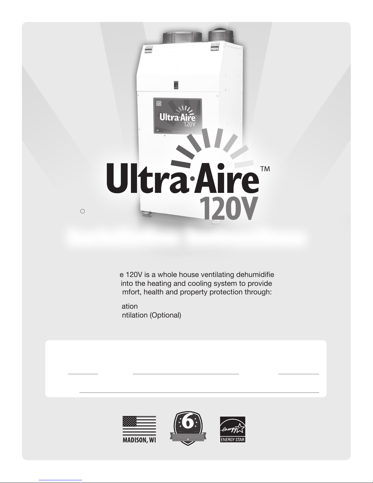
The Ultra-Aire 120V is a whole house ventilating dehumidier that
is integrated into the heating and cooling system to provide the
ultimate in comfort, health and property protection through:
• Dehumidication
• Fresh Air Ventilation (Optional)
• Air Filtration
TS-988 12/18 Rev E
P/N: 4036400 Serial No.: Install Date:
Sold by:
HVAC Installer: Please Leave Manual for Homeowner
Installation Instructions
YEAR
FULL WARRANTY
YEAR
FULL WARRANTY
INSTALLATION BY A HVAC PROFESSIONAL IS RECOMMENDED
Patent Pending
D Therma-Stor, LLC
7,246,503
Safety Instructions ...................................................................... 3
Specifications .............................................................................. 4
Optional Accessories................................................................... 5
Dehumidifier Set Up .................................................................... 6
Attaching Duct Collars................................................................. 7
Electrical Requirements .............................................................. 8
Drain Installation ......................................................................... 9
Ducting to HVAC Systems.......................................................... 10
Recommended HVAC System Installations ........................................ 11
Alternative HVAC System Installation ................................................. 12
Recommended Multiple HVAC Systems Installation .......................... 13
No Existing Ductwork Installation ....................................................... 14
Fresh Air Ventilation .................................................................. 15
Determine Ventilation Requirements ................................................... 16
Controls ..................................................................................... 17
Wiring Controls.................................................................................... 18
Air Filtration............................................................................... 18
MERV Rating Chart ............................................................................. 19
Service....................................................................................... 20
Troubleshooting................................................................................... 21
Warranty .................................................................................... 24
TABLE OF CONTENTS
Ultra-Aire is committed to manufacturing quality products. To maintain
our standards, product specications may change without notice.
4201 Lien Road, Madison, WI 53704
(800) 533-7533
www.Thermastor.com | www.Ultra-Aire.com
© 2017 Therma-Stor LLC

3
www.Ultra-Aire.com | (800) 533-7533 Ultra-Aire 120V Installation Instructions
SAFETY INSTRUCTIONS
WARNING!
THIS SYMBOL MEANS IMPORTANT INSTRUCTIONS. FAILURE TO HEED THEM
CAN RESULT IN SERIOUS INJURY OR DEATH.
READ THE INSTALLATION, OPERATION AND MAINTENANCE INSTRUCTIONS CAREFULLY
BEFORE INSTALLING AND OPERATING THIS DEVICE. PROPER ADHERENCE TO THESE
INSTRUCTIONS IS ESSENTIAL TO OBTAIN MAXIMUM BENEFIT FROM YOUR ULTRA-AIRE
WHOLE HOUSE VENTILATING DEHUMIDIFIER.
CAUTION!
THIS SYMBOL MEANS IMPORTANT INSTRUCTIONS. FAILURE TO HEED THEM
CAN RESULT IN INJURY OR MATERIAL PROPERTY DAMAGE.
Registrations
The Ultra-Aire 120V conforms to unied standard UL 60335-2-40 and CSA standard C22.2.60335-2-40.
CAUTION!
READ ALL INSTRUCTIONS BEFORE BEGINNING INSTALLATION.
ALWAYS USE CAUTION AND WEAR CUT RESISTANT GLOVES WHEN HANDLING SHEET
METAL.
IMPROPER INSTALLATION MAY CAUSE PROPERTY DAMAGE OR INJURY.
INSTALLATION, SERVICE, AND MAINTENANCE MUST BE PERFORMED BY A QUALIFIED
SERVICE TECHNICIAN.
DEHUMIDIFIER IS HEAVY. HANDLE WITH CARE AND FOLLOW INSTALLATION INSTRUCTIONS.
DO NOT USE IN POOL APPLICATIONS, OR WARRANTY WILL BE VOID.
NEVER OPERATE A UNIT WITH A DAMAGED POWER CORD. IF THE POWER CORD IS
DAMAGED, IT MUST BE REPLACED BY THE MANUFACTURER, ITS SERVICE AGENT, OR A
SIMILARLY QUALIFIED PERSON IN ORDER TO AVOID A HAZARD.
THIS APPLIANCE IS NOT INTENDED FOR USE BY PERSONS (INCLUDING CHILDREN) WITH
REDUCED PHYSICAL, SENSORY OR MENTAL CAPABILITIES, OR LACK OF EXPERIENCE
OR KNOWLEDGE, UNLESS THEY HAVE BEEN GIVEN SUPERVISION OR INSTRUCTION
CONCERNING THE USE OF THE APPLIANCE BY A PERSON RESPONSIBLE FOR THEIR
SAFETY. CHILDREN SHOULD BE SUPERVISED TO ENSURE THAT THEY DO NOT PLAY WITH
THE APPLIANCE.
WARNING!
120 VOLTS MAY CAUSE SERIOUS INJURY FROM ELECTRIC SHOCK.
DISCONNECT ELECTRICAL POWER BEFORE STARTING INSTALLATION OR
SERVICING, AND LEAVE POWER DISCONNECTED UNTIL INSTALLATION OR
SERVICE IS COMPLETED.

4Ultra-Aire 120V Installation Instructions www.Ultra-Aire.com | (800) 533-7533
SPECIFICATIONS
Part Number: 4036400
Blower: 445 CFM @ 0.0" WG 335 CFM @ 0.6" WG
390 CFM @ 0.2" WG 305 CFM @ 0.8" WG
360 CFM @ 0.4" WG
Power: 680 Watts @ 80°F and 60% RH
Supply Voltage: 115 VAC – 1phase – 60 Hz
Current Draw: 5.8 Amps
Transformer Protection: Push Button Reset (located near power cord)
Circuit Requirement: 15 Amps
Energy Factor: 3.60 L/kWh
Operating Range: 49°F Min, 95°F Max (Inlet Air Temperature)
34°F Min, 135°F Max (Outside Cabinet)
Sized For: Up to 3,000 Square Feet
Water Removal at: 80°F and 60% RH 70°F and 60% RH
Capacity: 124 Pints/Day 95 Pints/Day
Eciency: 7.6 Pints/kWh 6.5 Pints/kWh
Duct Connections: 6" Round Inlet; 10" Round Inlet; 8" Round Outlet (X3)
Air Filter: MERV-13, Standard Pleat
Eciency: 90% ASHRAE Dust Spot
Size: 16" x 20" x 2"
Optional Air Filter: MERV-14, Embossed Pleat
Eciency: 95% ASHRAE Dust Spot
Size: 16" x 20" x 4"
Power Cord: 9', 115 VAC, Ground
Internal Insulated Cabinet: Yes
Drain Connection: 3/4" Threaded Female NPT
Refrigerant Type: R410A
Refrigerant Amount: 2 lbs., 5 oz.
Dimensions:
Unit With Collars
Width: 26 3/4"
Height: 43 1/2"
Length: 22"
Weight: 120 lbs.
Unit Without Collars
Width: 20 1/2"
Height: 40 1/4"
Length: 18 3/4"
Weight: 118 lbs.
Shipping
Width: 25 1/4"
Height: 46 1/2”
Length: 22"
Weight: 145 lbs.
26 3/4"
With Collars Installed
20 1/2"
Without
Collars Installed
43 1/2"
With Collars Installed
40 1/4"
Without Collars Installed
Front View Side View
8"
Top View
18 3/4"
26 3/4"
With Collars Installed
10" 6"
10" 6" 10"
8"8"
8" 8"
18 3/4"

5
www.Ultra-Aire.com | (800) 533-7533 Ultra-Aire 120V Installation Instructions
OPTIONAL ACCESSORIES
4028539 DEH 3000 Control
4028407 DEH 3000R Control (with remote)
4039391 MERV-13 Filter (16" x 20" x 2")
4037733 MERV-13 Filter, 4-Pack
4037734 MERV-13 Filter, 12-Pack
4022489 MERV-14 Filter (16" x 20" x 4")
4039225 Pump Kit
4028616 Caster Kit
4023672 6" Motorized Damper
4026859 6" Flex Duct, 25'
4020128 6" Insulated Flex Duct, 25'
4020656 6" Inlet Hood
4023647 8" Gravity Damper
4027415 8" Flex Duct, 25'
4020177 8" Insulated Flex Duct, 25'
4026969 10" Flex Duct, 25'
4022126 10" Insulated Flex Duct, 25'
Items Included in Box:
• Ultra-Aire 120V Dehumidier
• Ultra-Aire 120V Installation Instructions
• 10" Duct, 8" Duct (x2), 6" Damper, 8" Duct Cover Plate
• 10" Duct Foam Tape, 33"
• 8" Duct Foam Tape, 26.75" (x2)
• 6" Duct Foam Tape, 18.5"
• Duct Fasteners (x14)
6Ultra-Aire 120V Installation Instructions www.Ultra-Aire.com | (800) 533-7533
Important Precautions
• The device is designed to be installed indoors in a space that is protected from rain and ooding.
• Install the unit with enough space to access the front panel for maintenance and service.
• Avoid directing the discharge air at people. The dehumidier should be used in the upright position.
• If used near a water source, be certain there is no chance the unit could fall into the water or get splashed and
that it is plugged into a dedicated circuit and Ground Fault Circuit Interrupter (GFCI) protected outlet.
• DO NOT use the dehumidier as a bench or table.
• DO NOT place the dehumidier directly on structural building members without vibration absorbers or unwanted
noise may result. Place the Ultra-Aire 120V on supports to raise the base of the unit.
• A drain pan with a oat switch MUST be placed under the dehumidier if installed above a living area or above
an area where water leakage could cause damage.
Location Considerations
• Allow sucient clearance to handle the unit’s overall dimensions as well as the necessary return and supply duc-
twork to the unit.
• Allow sucient clearance for lter removal and to prevent airow obstruction.
• Electrical service access will require the removal of the front panel. Allow sucient clearance on this side of the unit.
• Locate the dehumidier in an area where the cord’s length (9') easily reaches a 115 VAC electrical outlet with a
minimum of a 15 Amp circuit capacity.
• Locate the dehumidier in an area where eld wiring the control (low voltage) to the unit will be possible.
• It is recommended that a backdraft damper be used in the discharge duct of the Ultra-Aire 120V, especially
when connecting to the supply ducting system. The backdraft damper prevents supply air from counter
owing through the Ultra-Aire 120V when it is not operating. The dehumidier’s location should be chosen to
allow installation of this accessory if necessary.
• DO NOT hang the
Ultra-Aire 120V
from its cabinet.
• Allow for proper
routing and drainage
of needed drain pipes.
70°F and 60% RH
90 pints/day
6.0 Pints/kWh
Shipping
24”
49”
21”
138 lbs.
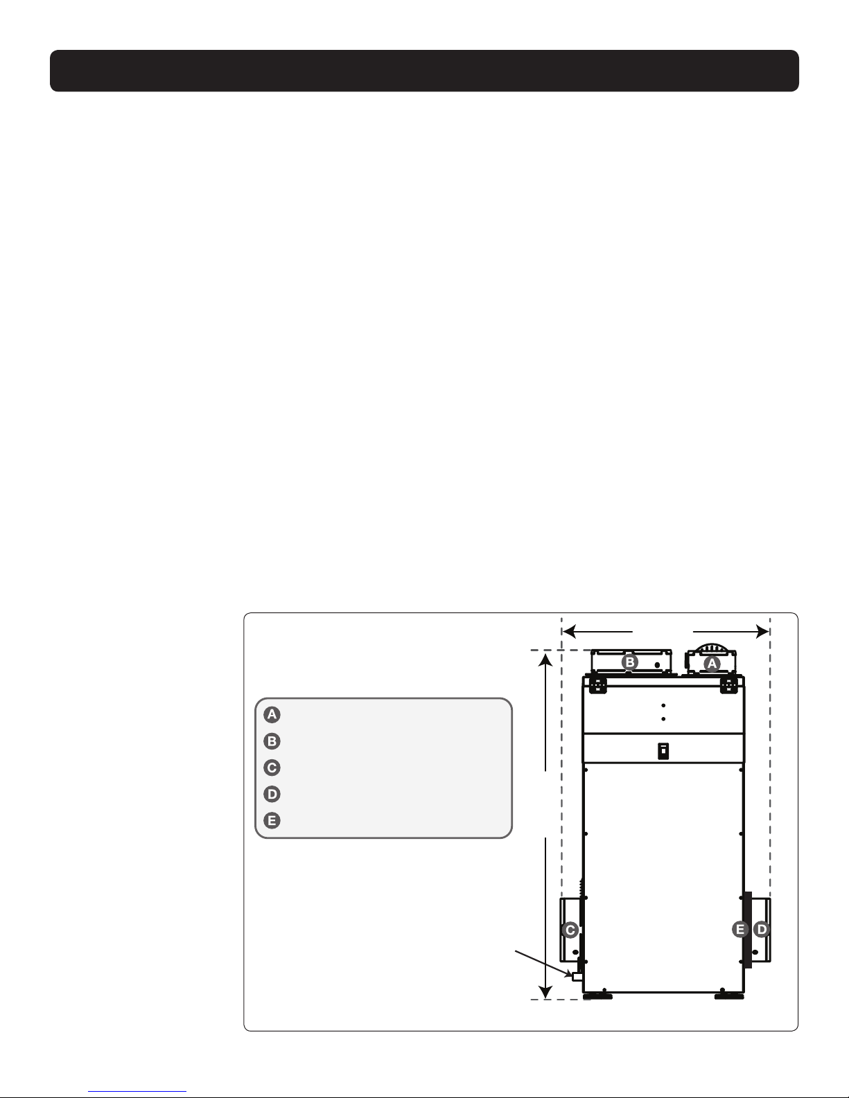
3/4" FPT Fitting
6" Fresh Air Intake (Optional)
10" Return Air Duct
8" Supply Air Duct #1
26 3/4"
43 1/2"
Front View
Electrical service
access is through
the front panel
of dehumidifier.
8" Supply Air Duct #2 (Optional)
8" Duct Cover (Optional)
DEHUMIDIFIER SET UP
7
www.Ultra-Aire.com | (800) 533-7533 Ultra-Aire 120V Installation Instructions
70°F and 60% RH
90 pints/day
6.0 Pints/kWh
Shipping
24”
49”
21”
138 lbs.
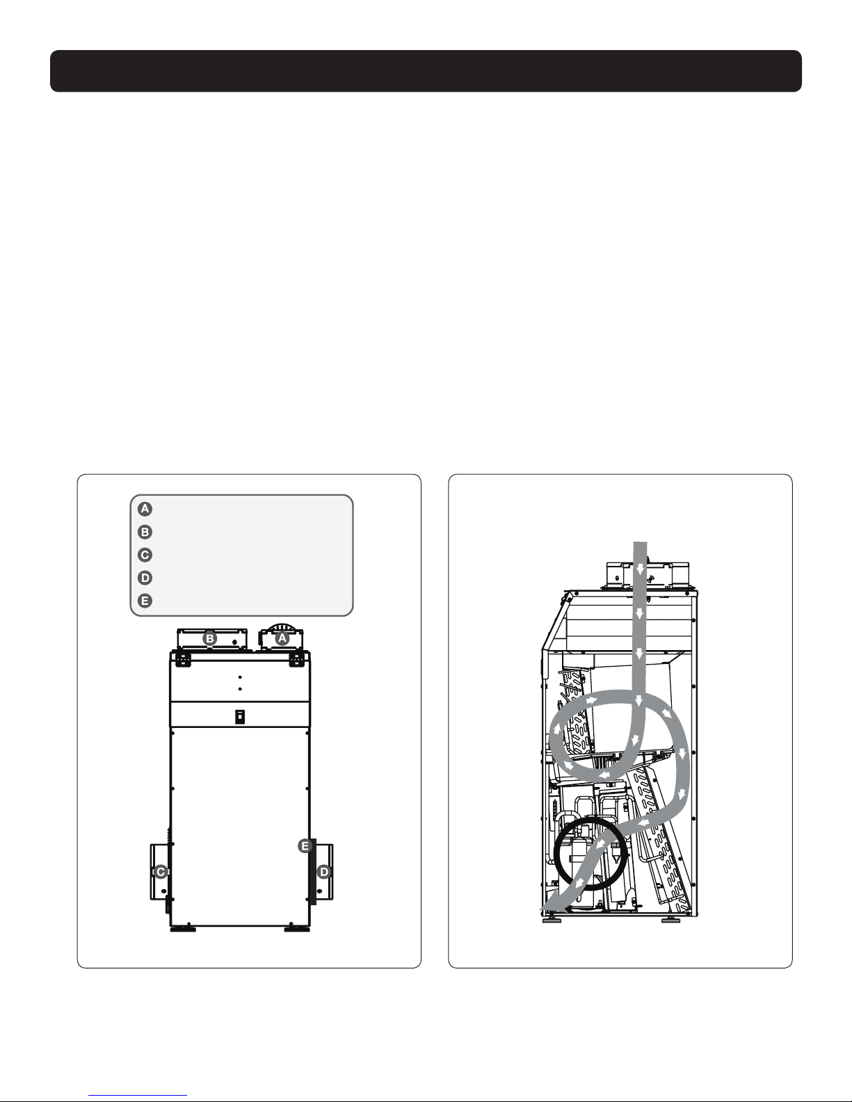
6" Fresh Air Intake (Optional)
10" Return Air Duct
8" Supply Air Duct #1
Front View
8" Supply Air Duct #2 (Optional)
8" Duct Cover (Optional)
ATTACHING DUCT COLLARS
Before installing the damper and duct collars listed below, apply the corresponding foam tape included for each.
Fresh Air Ventilation Duct
Fresh air ventilation is optional. A 6"diameter damper is included with the unit and can be attached to the top
using the corresponding foam tape provided. The 6" damper should be closed if fresh air is not desired. If setting
up the unit to provide fresh air ventilation, see page 17.
Return Air Inlet
A 10"diameter duct collar is included with the unit and can be attached to the top with the corresponding
foam tape provided.
Supply Air Outlet #1
An 8"diameter duct collar is included with the unit and can be attached to the side using the corresponding
foam tape provided.
Supply Air Outlet #2
An optional 8"diameter duct collar is included with the unit and can be attached to the other side with the
corresponding foam tape provided.
Supply Air Duct Cover
An optional 8” diameter duct cover (attached) can be used to block one of the supply air outlets if not being used.
Side View
Air Flow Path
8Ultra-Aire 120V Installation Instructions www.Ultra-Aire.com | (800) 533-7533
The Ultra-Aire 120V plugs into a common grounded 115 VAC outlet. The device draws 5.8 Amps at 80°F
and 60% RH. Locate the dehumidier in an area where the cord’s length (9') easily reaches a 115 VAC
electrical outlet with a minimum of 15 Amp circuit capacity. If used in an area that may become wet, a GFCI
protected circuit is recommended. Consult local electrical codes for further information.
Ultra-Aire oers a variety of control devices for use with the Ultra-Aire 120V. The control is to be located
remotely from the dehumidier and placed in the space to be conditioned. A low voltage (24 Volt) control MUST
be used with the Ultra-Aire 120V and MUST be connected with low voltage (18-22 gauge) thermostat wire.
ELECTRICAL REQUIREMENTS
CAUTION!
DO NOT ALLOW THE 24V TERMINAL TO CONTACT THE COM TERMINAL ON THE ULTRA-AIRE
120V OR DAMAGE TO THE TRANSFORMER WILL RESULT.
Electrical Precautions
• Do not install the control where it may not accurately sense the relative humidity such as near HVAC
supply registers, near exterior doors, on an outside wall, near a window, or near a water source.
• The terminals on the Ultra-Aire 120V and the control are labeled to prevent confusion.
• Be sure to consult the electrical schematic in the CONTROLS Section (Page 17) of this manual or inside
the access panel of the Ultra-Aire 120V before making control connections.
WARNING!
THE REMOTE CONTROLS OF THE ULTRA-AIRE 120V ARE POWERED BY A LOW VOLTAGE CIRCUIT
(24 VAC) AND MUST NEVER CONTACT OR BE CONNECTED TO A HIGH VOLTAGE CIRCUIT.
CAUTION!
SOME OF THE TERMINALS ON THE ULTRA-AIRE 120V MAY NOT BE USED WITH CERTAIN
CONTROLS AND SHOULD BE LEFT UNCONNECTED.
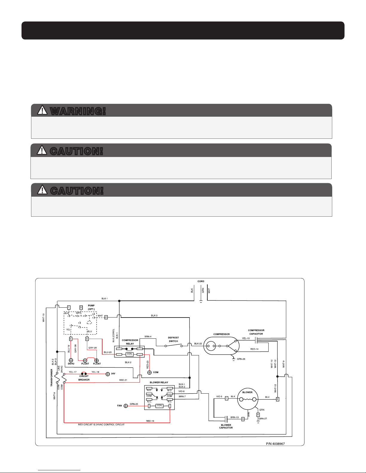
Wiring Diagram

9
www.Ultra-Aire.com | (800) 533-7533 Ultra-Aire 120V Installation Instructions
The Ultra-Aire 120V generates condensate.
Place a secondary drain pan with a oat switch under the dehumidier if it is suspended above a nished
area or above an area where water leakage could cause damage.
The Ultra-Aire 120V contains an internal drain trap for proper dehumidier operation. Install a 3/4” threaded
male NPT adapter to the external condensate tting. Install a drain pipe assembly utilizing 3/4” PVC pipe to
transport the condensate to a drain. Pitch of drain should be 1" per 10'.
An optional condensate pump kit is available for use with the Ultra-Aire 120V and may be installed if lift is
required to dispose of condensate. Condensate is automatically pumped to a remote location when the
water level in the pump’s reservoir rises to close the oat switch.
The pump also contains a safety oat
switch. If the pump fails, this switch opens
the common control circuit and stops water
production before the reservoir overows.
Note: An optional condensate pump kit can
be purchased through your dealer or online.
Refer to the kit literature for installation
instructions.
Side View
Supply
Air
Outlet 3/4" FPT
Fitting
DRAIN INSTALLATION
Drain Installation

10 Ultra-Aire 120V Installation Instructions www.Ultra-Aire.com | (800) 533-7533
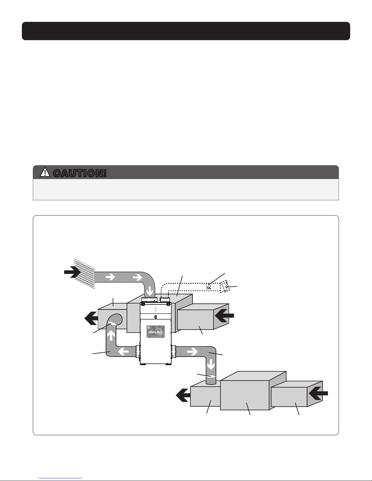
The recommended installation creates a separate return for the Ultra-Aire 120V in a central area of the
structure. Duct the supply of the unit to the air supply of the existing HVAC system. Connect an insulated
duct from outside to the 6" damper of the Ultra-Aire 120V to provide fresh make-up air.
DUCTING TO HVAC SYSTEMS
CAUTION!
DO NOT CONNECT WITH A STATIC PRESSURE GREATER THAN OR EQUAL TO +0.8 WG.
CONTACT TECHNICAL SUPPORT AT (800) 533-7533 FOR ADDITIONAL DETAILS.
Ducting Considerations:
• All exible ducting connected to the Ultra-Aire 120V should be UL listed.
• A short piece of exible ducting on all Ultra-Aire 120V duct connections is recommended to reduce noise
and vibration transmitted to rigid ductwork in the structure.
• Use a minimum 8" (10" for inlet) diameter round or equivalent rectangular duct for total duct lengths of up
to 25'. Use a minimum 10" (12" for inlet) diameter round or equivalent rectangular duct for longer lengths.
• Grills or diusers on the duct ends must not excessively restrict airow.
• A length of 10' or more of insulated ex duct or any other vibration isolating material on the outlet of the
Ultra-Aire 120V will reduce air noise from the blower.
• Eective dehumidication may require that ducting be branched to isolated, stagnant air ow areas.
When ducting to two or three areas, use 8" or larger diameter branch ducting. When ducting to four or
more areas, use 6" or larger diameter branch ducting. Provisions must be made to provide airow from
supply locations to the central return location. Proper air distribution is important to ensure even humidity
control and heat distribution throughout the structure.
• DO NOT locate the return in a bathroom or a kitchen.
11
www.Ultra-Aire.com | (800) 533-7533 Ultra-Aire 120V Installation Instructions
HVAC
Supply
Ultra-Aire
Supply
HVAC
Return
Ultra-Aire
Return
Fresh Air Intake
(Optional)
Backdraft
Damper
Motorized
Damper
Duct Cover Plate
Backdraft
Damper
Air Handler Supply
Ultra-Aire Supply
Fresh Air Intake
(Optional)
Indoor
A
ir Return
Motorized
Damper
Duct Cover Plate
Recommended HVAC System Installations
DUCTING TO HVAC SYSTEMS
• Install a dedicated return for the Ultra-Aire
120V from a central area of the structure.
• Install an insulated duct from outside to the
6" damper of the Ultra-Aire 120V to provide
fresh air ventilation (optional).
• The optional second supply of the Ultra-Aire
120V may be ducted to another location. This
can provide a second source of airow to the
basement or supply of the existing HVAC
system with a backdraft damper.
• When using only one of the two supplies on
the Ultra-Aire 120V, the unused supply must be
blocked using the duct cover plate included.
• DO NOT locate return in a bathroom or kitchen.
• Control should be located remotely from the
dehumidier and placed in a central location.
Dedicated Ultra-Aire Return to HVAC Supply
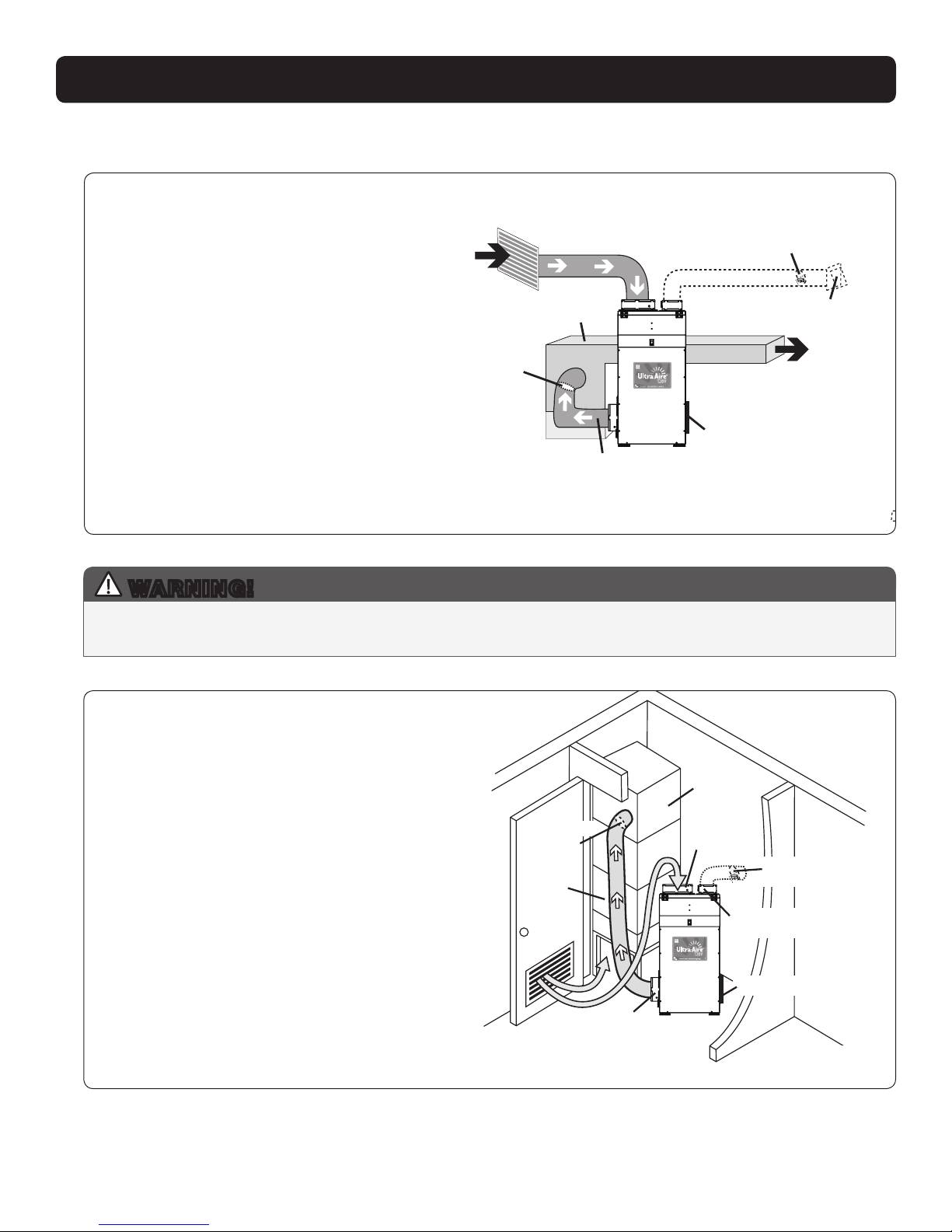
• Locate the dehumidier under or next to the HVAC system
as space allows. A passive vent or louver door with a
minimum net free area of 1 square foot is required to
allow air to be pulled in from the living space.
• No inlet duct is required. Air is pulled through the
passive vent or louver door from the living space.
Where outlet space is restricted, the outlet duct
collar is optional.
• Install an insulated duct from outside to the 6" collar
of the Ultra-Aire 120V to provide fresh air ventilation. If
the fresh air ventilation duct is to be used, the return of
the Ultra-Aire 120V must be ducted or an inline fan may
be required on the fresh air ventilation line to bring in
outside air.
• Duct the supply of the Ultra-Aire 120V to the supply of
the existing HVAC system with a backdraft damper.
• Control should be located remotely from the
dehumidier and placed in a central location.
WARNING!
WHEN INSTALLING THE DEHUMIDIFIER AS PART OF A COMBUSTION TYPE HVAC SYSTEM (GAS,
OIL, PROPANE, ETC.), FOLLOW ALL LOCAL AND NATIONAL BUILDING AND SAFETY CODES.
Closet Installation - Central Return to HVAC Supply

12 Ultra-Aire 120V Installation Instructions www.Ultra-Aire.com | (800) 533-7533
Ultra-Aire Supply
Air Handler
HVAC Return
HVAC Return to A/C Supply
HVAC Supply Fresh Air
Intake
(Optional)
Backdraft Damper
Motorized
Damper
Optional Check Damper
(no HVAC fan needed)
Duct Cover Plate
DUCTING TO HVAC SYSTEMS
Alternative HVAC System Installation
If the Recommended Dedicated Ultra-Aire Return to HVAC Supply Installation is not possible, there are
alternative installation options available.
• DO NOT locate return in a bathroom or kitchen.
• Control should be located remotely from the dehumidier and placed in a central location.
• For basement installations, an optional tee can be installed on the Ultra-Aire Supply.
HVAC Return to HVAC Supply
Check Damper should be in place between
the Return and Supply connections of the
dehumidier.
If Check Damper is not in place, the
HVAC fan must turn on when the
dehumidier is in operation.
13
www.Ultra-Aire.com | (800) 533-7533 Ultra-Aire 120V Installation Instructions
DUCTING TO HVAC SYSTEMS
The Ultra-Aire 120V can be installed on multiple HVAC systems. Dehumidied air will be provided to both
HVAC systems for distribution throughout the structure.
• The use of one to two Supply Ducts may be used when installing on multiple HVAC systems.
• Backdraft dampers are required in the supply ducts.
• DO NOT locate the return in a bathroom or kitchen.
• One control will service both HVAC zones. Control should be located remotely from the dehumidiers and
placed in a central location.
• HVAC systems should be in close proximity for optimal air ow.
• For multiple systems, contact Technical Support at (800) 533-7533.
Recommended Multiple HVAC Systems Installation
HVAC
Supply
Ultra-Aire
Supply
First Air Handler
Dedicated Ultra-Aire 90 Return to multi systems A/C Supply
HVAC Return
Backdraft
Damper
Second Air Handler HVAC Return
HVAC
Supply
Backdraft
Damper
Indoor
Air Return
Fresh Air
Intake
(Optional)
Motorized
Damper
Ultra-Aire
Supply
Dedicated Ultra-Aire Return to Multiple HVAC Systems
CAUTION!
DO NOT CONNECT WITH A STATIC PRESSURE GREATER THAN OR EQUAL TO +0.8 WG.
CONTACT TECHNICAL SUPPORT AT (800) 533-7533 FOR ADDITIONAL DETAILS.
The dual 8" supply outlets of the Ultra-Aire 120V can both be used to supply airow to multiple HVAC
systems, each with a backdraft damper, without requiring a tee duct to split.
14 Ultra-Aire 120V Installation Instructions www.Ultra-Aire.com | (800) 533-7533
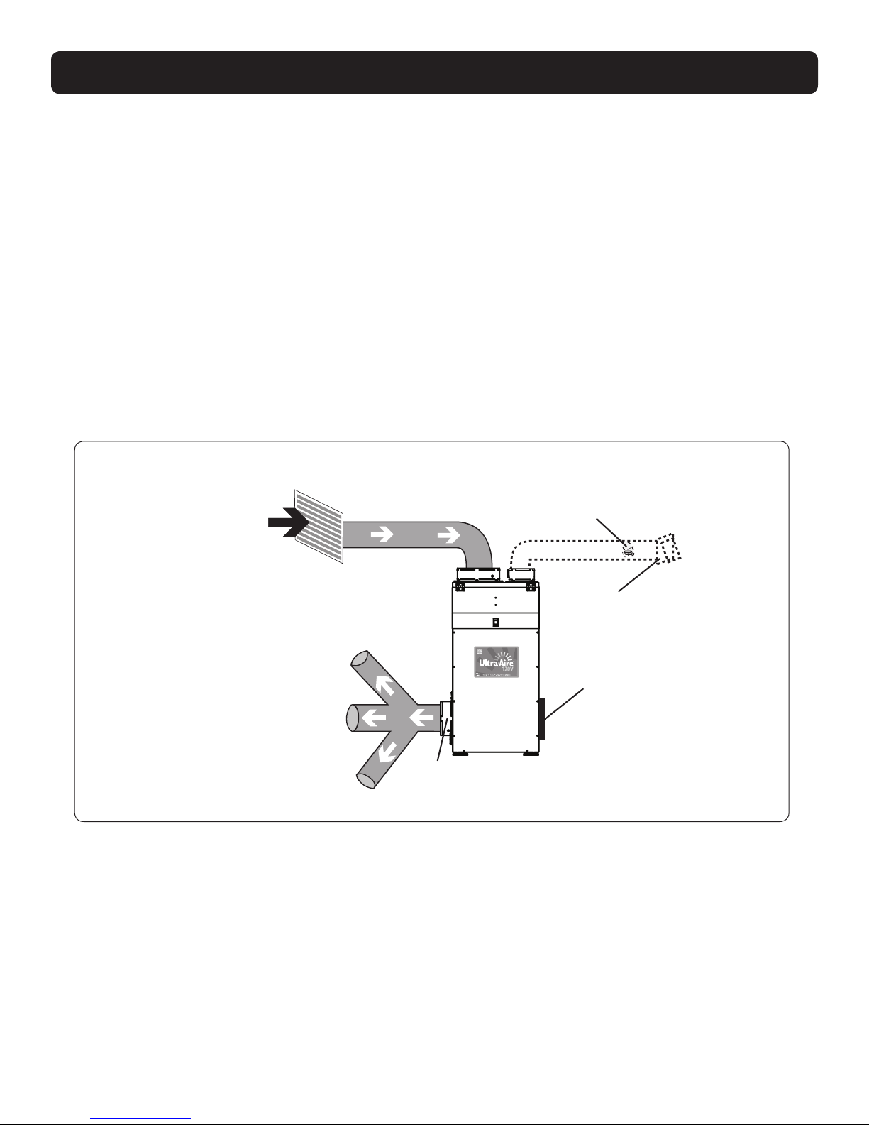
DUCTING TO HVAC SYSTEMS
When installing the Ultra-Aire 120V in a structure that does not have a forced air HVAC system, a single
return for the Ultra-Aire 120V should be installed in a central location.
Install an insulated duct from outside to the 6" collar of the Ultra-Aire 120V to provide fresh air
ventilation (optional).
The supply of the Ultra-Aire 120V should be ducted to remote areas of the structure such as bedrooms, living
room, den, etc. Either one or two supply ducts may be used to distribute air. Be sure to utilize multiple rooms
to allow air inside the structure to properly circulate. Proper air distribution is important to ensure even
humidity control and heat distribution throughout the structure.
A 6" diameter duct is recommended for branches to bedrooms. An 8" diameter duct is recommended for
branches to larger areas.
• DO NOT locate the return in a bathroom or kitchen.
• DO NOT locate the supply in rooms where doors may be closed.
• Control should be located remotely from the dehumidier and placed in a central location.
Indoor
Air Return
Fresh Air
Intake
(Optional)
Motorized
Damper
Ultra-Aire
Supply
Duct Cover Plate
No Existing Ductwork Installation
No Existing Ductwork Installation
15
www.Ultra-Aire.com | (800) 533-7533 Ultra-Aire 120V Installation Instructions
Fresh air ventilation is optional.
Fresh air may be brought into the structure by connecting an insulated duct from outside the structure to
the 6" inlet of the Ultra-Aire 120V. A ventilation control is needed to program the time and frequency that
the unit introduces outside air. The time and frequency of ventilation should be based on the size and
occupancy of the residence.
• The fresh air ventilation duct should be connected to the 6" damper on the top of the Ultra-Aire 120V.
• An insulated 6" diameter duct provides up to 100 CFM of outside air.
• If the fresh air ventilation duct is to be used, the return of the Ultra-Aire 120V must be ducted or an inline
fan may be required on the fresh air ventilation line to bring in outside air.
• If a motorized damper is not being used, fresh air is controlled by the manual damper in the 6” collar of the
Ultra-Aire 120V.
• Performance of the Ultra-Aire 120V can be impacted by inside and outside air conditions.
• When a 6" motorized damper is used, a digital control is required.
• It may be necessary to use 8" duct work if additional fresh air is required.
• In cold climates or at times when the dew point is low, ventilation can be used to dehumidify the
structure, making the Ultra-Aire 120V capable of year-round drying.
FRESH AIR VENTILATION
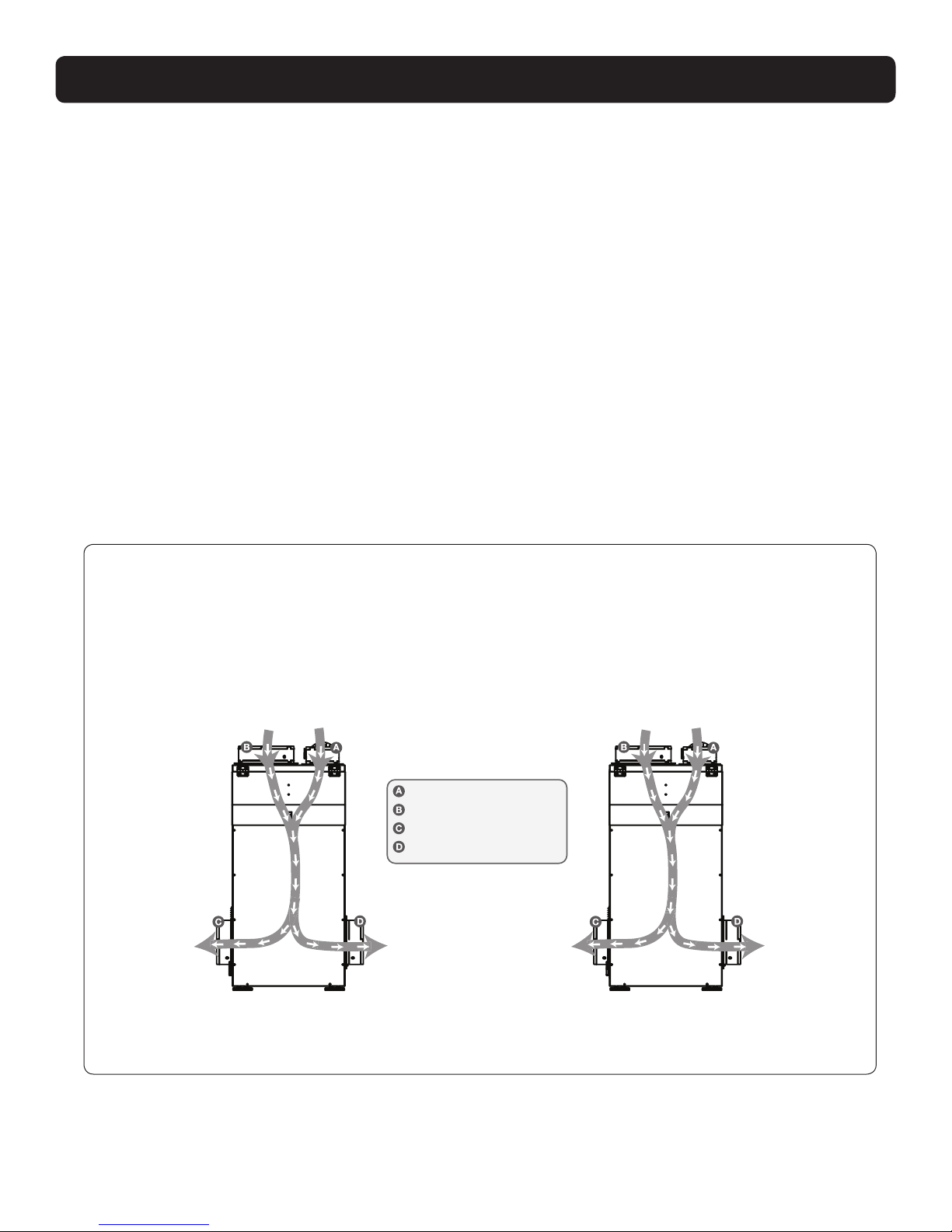
Fresh Air Ventilation With Dehumidier O and Fan Only Operation
Outside air mixes with the dehumidier’s return air before being supplied to the home. Outside
temperature, inside temperature and relative humidity will impact the combined outlet air conditions.
Note: Temperature and relative humidity may vary depending on duct distribution scheme.
70°F and 60% RH
90 pints/day
6.0 Pints/kWh
Shipping
24”
49”
21”
138 lbs.
6" Fresh Air Intake (Optional)
10" Return Air Duct
8" Supply Air Duct #1
8" Supply Air Duct #2 (Optional)
Front
View
Hot Climate Cold Climate
Indoor Air
70°F, 50%RH
Outdoor Air
90°F, 65%RH
Indoor Air
70°F, 50%RH
Outdoor Air
30°F, 65%RH
Outlet Air
76°F, 59%RH
Outlet Air
76°F, 59%RH
Outlet Air
59°F, 60%RH
Outlet Air
59°F, 60%RH
Front
View

16 Ultra-Aire 120V Installation Instructions www.Ultra-Aire.com | (800) 533-7533
Option 1: Calculating Airflow Requirement Using ASHRAE 62.2-2016 Airflow Equation
ASHRAE Airow in CFM = [House Area in Sq.Ft. x 0.03] + [(Number of Bedrooms +1) x 7.5]
NOTE: Use ‘Number of Bedrooms + 1’ or ‘Number of Occupants’, whichever is larger.
Example 1: Number of Bedrooms + 1
1800 square foot house with 3 bedrooms, 4 occupants = [1800 X 0.03] + [(3+1) X 7.5] = 84 CFM
Example 2: Number of Occupants
1800 square foot house with 3 bedrooms, 5 occupants = [1800 X 0.03] + [5 X 7.5] = 91.5 CFM
Record the required CFM ____________
FRESH AIR VENTILATION
Determine Ventilation Requirements
The MINIMUM ventilation requirement is calculated using ASHRAE 62.2-2016. Use one or both of the options
below to determine your ventilation requirement. Follow all local and national building and safety codes.
Option 2: Calculating Airflow Requirement Using Table 4.1 from ASHRAE 62.2-2016
Ventilation Air Requirements, CFM
Floor Area
(ft2)
< 500
501 - 1000
1001 - 1500
1501 - 2000
2001 - 2500
2501 - 3000
3001 - 3500
1
30
45
60
75
90
105
120
2
38
53
68
83
98
113
128
3
45
60
75
90
105
120
135
4
53
68
83
98
113
128
143
5
60
75
90
105
120
135
150
Number of Bedrooms
Table 4.1 from ASHRAE 62.2-2016
Record the required CFM ____________

17
www.Ultra-Aire.com | (800) 533-7533 Ultra-Aire 120V Installation Instructions
CONTROLS
A control must be used with the Ultra-Aire 120V. Ultra-Aire oers the DEH 3000 proprietary control. The DEH 3000
allows homeowners to monitor and control relative humidity and proper ventilation levels in their home. This control is
also available with a remote sensing option.
Note: The DEH 3000 is sold separately and can be purchased online or through your local dealer. Other
thermostats are compatible with the Ultra-Aire 120V.
CAUTION!
DO NOT ALLOW THE 24V TERMINAL FROM THE ULTRA-AIRE 120V TO CONTACT THE COM TERMINAL
ON THE ULTRA-AIRE 120V OR DAMAGE TO THE TRANSFORMER WILL RESULT.
Wiring Controls
Circuit Breaker
To prevent damage to the 24 volt control transformer, the Ultra-Aire 120V comes
with a resettable circuit breaker. Check wiring for any electrical short and repair
before resetting breaker. Resetting the circuit breaker without correcting the
electrical short may result in transformer damage. Be sure to check the electrical
schematic in this manual or inside the access panel of the Ultra-Aire 120V before
making any control connections. The reset button for the circuit breaker can be
found on the side of the unit.
Control Connections
The control and the Ultra-Aire 120V are labeled to prevent confusion. Depending
on the control, some of the screw terminals on the Ultra-Aire 120V may not be
used. Be sure to consult the electrical schematic in this manual or inside the
access panel of the Ultra-Aire 120V before making control connections.
Side View
Circuit Breaker
Reset Button
A low voltage control must be used with the Ultra-Aire 120V.
COM 24VAC Power Transformer Neutral Side
FAN Fan Control
24V Transformer High Side
DEHU Dehumidication (Fan and Compressor) Control
FLOAT External low voltage oat switch or water sensor (two terminals).
Use normally closed switch.
Terminal Block Control Operation:
Compressor ON / Fan ON Make contact between 24V and DEHU terminals
Compressor OFF / Fan ON Make contact between 24V and FAN terminals
Power HVAC Accessory Connect the accessory to the COM and 24V terminals
Between the COM lead and the 24V TERMINAL is a 40VA transformer. This low voltage power source
powers the relay coils which control the fan and compressors. This 24VAC transformer can also be
used to power HVAC accessories external to the dehumidier.
NOTE: 18 gauge wire needed between the Ultra-Aire 120V dehumidier and the external control.

18 Ultra-Aire 120V Installation Instructions www.Ultra-Aire.com | (800) 533-7533
The Ultra-Aire 120V is equipped with a MERV-13 lter. An optional MERV-14 lter is available at
www.ThermastorFilters.com. The MERV-13 lter should be checked and replaced every three to six months.
If the MERV-14 lter is used, the MERV-13 should act as a pre-lter and sit on top of the MERV-14 lter.
Replacing the MERV-13 lter every three to six months extends the life of the MERV-14 lter. The MERV-14 lter
should be replaced every two to three years if a MERV-13 is used as a pre-lter and replaced every three to
six months. Operating the unit with a dirty lter will reduce dehumidier capacity and eciency.
DO NOT operate the unit without the recommended lter. Filter non-compliance voids the product warranty.
AIR FILTRATION
Changing the Filter
For greatest ltration and eciency of
the Ultra-Aire 120V, it is recommended
the air lter be replaced every three to
six months with a MERV-13 lter.
Step 1: The lter access door is located
above the front panel of the dehumidier.
Pull straight up on the door latch to disengage
from the front panel, then lift door to it’s
vertical position.
Step 2: Remove the used lter(s)
from the housing. Insert the new lter by
gently pushing it straight into the lter
cavity. Make sure the air ow arrows on
the lter are pointing down into the unit.
Step 3: Close the lter access door by
pushing up on the door latch, inserting the
latch into the front panel, then releasing.
Ensure that the latch is rmly engaged
with the front panel.
CAUTION!
MAKE SURE UNIT IS OFF BEFORE CHANGING THE FILTER.
Side View
Filter
Access
Door
Filter
Filter Cavity
Pull Out
Side View
Filter
Access
Door
Filter
Filter Cavity
Push In
Side View
Filter
A
ccess
Door
Filter
Access
Door
Side
View
Side View
Filter
Access
Door
Filter
Filter Cavity
Pull Out
Side View
Filter
Access
Door
Filter
Filter Cavity
Push In
70°F and 60% RH
90 pints/day
6.0 Pints/kWh
Shipping
24”
49”
21”
138 lbs.
Front View
Door
Latch
Filter
Access
Door
Side View
70°F and 60% RH
90 pints/day
6.0 Pints/kWh
Shipping
24”
49”
21”
138 lbs.
Front View
Door
Latch
Filter
Access
Door
Side View
Side View
Filter
A
ccess
Door
Step 1
Step 2
Step 3

19
www.Ultra-Aire.com | (800) 533-7533 Ultra-Aire 120V Installation Instructions
AIR FILTRATION
Standard 52.5 Minimum
Efficiency Reporting
Value
Dust Spot
Efficiency Arrestance
Typical Controlled
Contaminant
Typical Applications and
Limitations Typical Air Filter/Cleaner Ty pe
20 n/a n/a < 0.30 pm particle size Cleanrooms
>99.999% eff. On .10-.20 pm
Particles
19 n/a n/a Virus (unattached) Radioactive Materials
p
Particles
18 n/a n/a Carbon Dust Pharmaceutical Man.
p
Particulates
17 n/a n/a All Combustion smoke Carcinogenetic Materials >99.97% eff. On .30 pm Particles
16 n/a n/a .30-1.0 pm Particle Size General Surgery Bag Filter-Nonsupported
15 >95% n/a All Bacteria Hospital Inpatient Care microfine fiberglass or
14 90-95% >98% Most Tobacco Smoke Smoking Lounges
synthetic media, 12-36 in. deep,
6-12 pockets.
13 89-90% >98% Proplet Nuceli (Sneeze) Superior Commercial Buildings
Box Filter - Rigid Style Cartridge
Filters 6 to 12" deep may use
lofted or paper media.
12 70-75% >95% 1.0-3.0 pm Particle Size Superior Residential Bag Filter-Nonsupported
Legionella microfine fiberglass or
1160-65% >95% Humidifier Dust Better Commercial Buildings
synthetic media, 12-36 in. deep,
6-12 pockets.
Lead Dust
10 50-55% >95% Milled Flour
Box Filter - Rigid Style Cartridge
Filters 6 to 12" deep may use
lofted or paper media.
Auto Emissions Hospital Laboratories
940-45% >90% Welding Fumes
830-35% >90% 3.0-10.0 pm Particle Size Commercial Buildings
Pleated Filters - Disposable,
extended surface area, thick with
Mold Spores
cotton-polyester blend media,
cardboard frame.
725-30% >90% Hair Spray Better Residential
Fabric Protector
Cartridge Filters-Graded density
viscous coated cube or pocket
filters, synthetic media.
6<20% 85-90% Dusting Aids Industrial Workplace
Cement Dust
Throwaway - Disposable
synthetic panel filter.
5<20% 80-85% Pudding Mix Paint Booth Inlet
4<20% 75-80% >10.0 pm Particle SizeMinimal Filtration
Throwaway - Disposable
fiberglass or synthetic panel filter.
Pollen
3<20% 70-75% Dust Mites Residential Washable - Aluminum Mesh.
Sanding Dust
2<20% 65-70% Spray Paint Dust
Textile Fibers Window A/C Units
Electrostatic-Self charging
woven panel filter.
1<20% <65% Carpet Fibers
MERV Rating Chart
Table Data Source: United States Environmental Protection Agency
20 Ultra-Aire 120V Installation Instructions www.Ultra-Aire.com | (800) 533-7533
WARNING!
SERVICING THE ULTRA-AIRE 120V WITH ITS HIGH PRESSURE REFRIGERANT SYSTEM AND
HIGH VOLTAGE CIRCUITRY PRESENTS A HEALTH HAZARD WHICH COULD RESULT IN DEATH,
SERIOUS BODILY INJURY, AND/OR PROPERTY DAMAGE. SERVICE MUST BE PERFORMED BY
A QUALIFIED SERVICE TECHNICIAN.
If the refrigerant charge is lost due to service or a leak, the leak should be repaired and a new charge must
be accurately weighed in. If any of the old charge is left in the system, it must be recovered before weighing
in the new charge. Refer to the unit nameplate for the correct charge weight and refrigerant type.
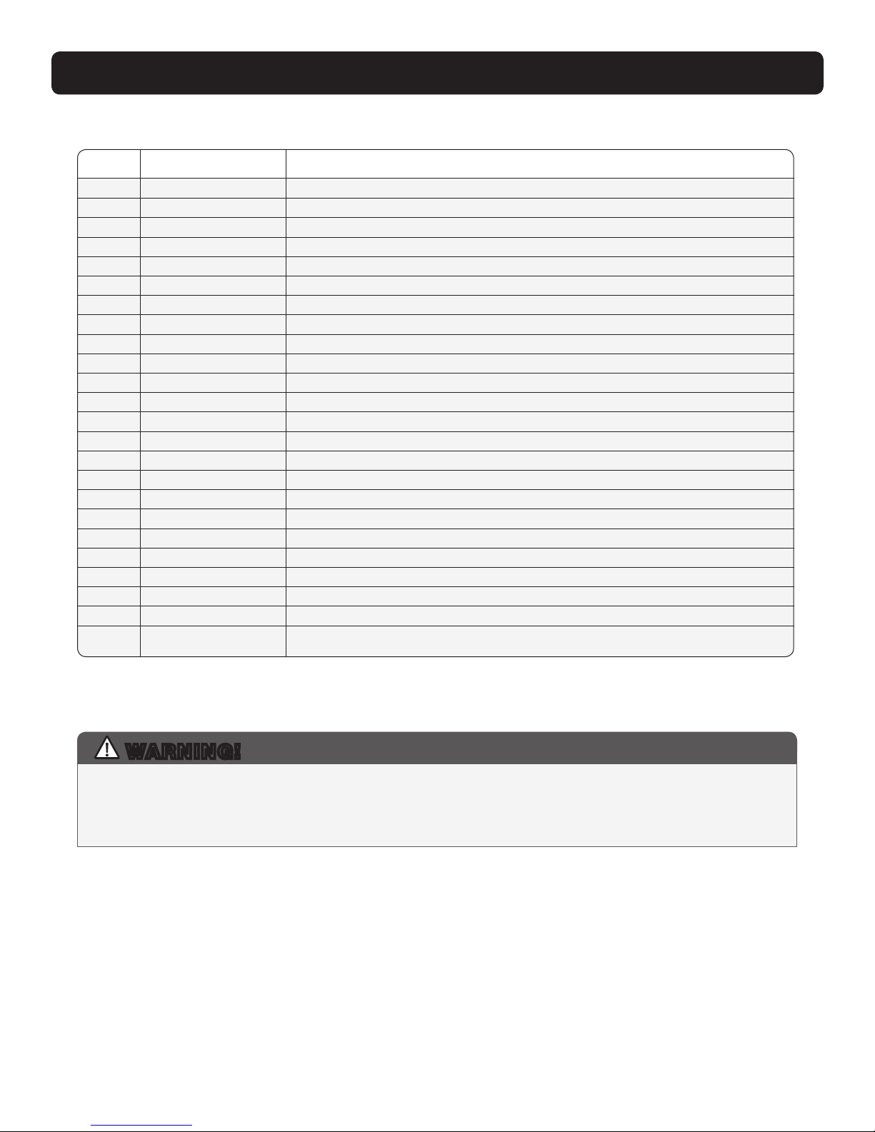
SERVICE
Service Parts List
ITEM PART NO. DESCRIPTION
1 4035852 Compressor
2 4035872 Overload, Compressor
3 4034474-05 Evaporator Coil
4 4028566 Condenser Coil
5 4029510 Filter / Drier
6 4036164-03 Capillary Tubes
7 4038071 Fan (Blower)
8 4022484 Relay, SPST, 24VAC, 30A
9 4029575 Relay, DPDT, 24VAC, 30A
10 4033032-05 Run Capacitor, 45 MFD, 370V
11 4035235-07 Fan Capacitor, 15 MFD, 370V
12 4036967 Thermostat, Defrost
13 4022487 Transformer, 120/24 VAC, 40A
14 4036559 Circuit Breaker, 3A
15 4036523 Power Cord
16 4038968 Wire Harness
17 4038967 Wiring Diagram
18 4026221 Leveling Feet
19 4029894 Hose, Drain Pan .56" ID X 24"
20 4037789 Slide Latch
21 4038693 Hinge
22 4029828 Duct, Inlet, 10" Plastic
23 4029829 Duct, Inlet, 6" Plastic With Damper
24 4029588 Duct, Outlet, 8" Plastic
Refrigerant Charging
This manual suits for next models
1
Table of contents
Other thermastor Fan manuals


Popular Fan manuals by other brands

inVENTer
inVENTer iV-Smart+ installation instructions

Danfoss
Danfoss air installation manual

AERMEC
AERMEC Omnia HL PC Series Use and installation manual

aerauliqa
aerauliqa Quantum MX installation manual

Flex-a-Lite
Flex-a-Lite Black Magic 175 installation instructions

Hunter
Hunter Gatlinburg installation manual


