Thermix KPH 1300-B Operation manual
1
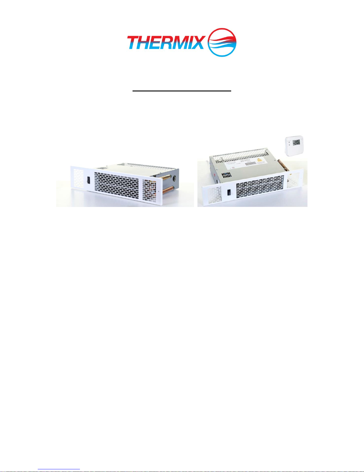
Installation & User Guide
Kitchen Plinth Heater models
KPH 1300-B
KPH 1500-C, KPH 1800-C & KPH 2100-C
KPH 1500-W, KPH 1800-W & KPH 2100-W
Classic models Wireless models
Introduction
This heater is intended to install behind the plinth in the space under the kitchen cupboards. However,
it can be installed in similar kind of application.
This unit is made for two pipe pumped central heating systems. Flow and return and pipes should be
connected as per drawing mentioned in page 2.This unit should not be installed in one pipe system.
To allow enough airflow a minimum clearance 0f 20-25mm from the top of the unit to the any shelving.
This unit must be installed of flat surface to avoid vibration.
Isolating valves (not supplied) should be fitted to both pipes (flow & return) to allow easy servicing.
The flexible hose should be fitted to both pipe (flow & return) to allow easy servicing.
This unit should not be installed in bath room or high humid areas.
Electrical connections should be via 3A fused spur and it should be accessible after the installation.
The following items should be in the carton:
Product complete with pre-wired mains cable.
Flexible connecting Hoses (Not provided with KPH-1300B)
Fitted Grille
Fixing screws (2)
Wireless Thermostat (for Model KPH 1500-W, KPH 1800-W & KPH 2100-W Only)
In the event of any items missing or visibly damaged, please contact us by email.
2
Installation:
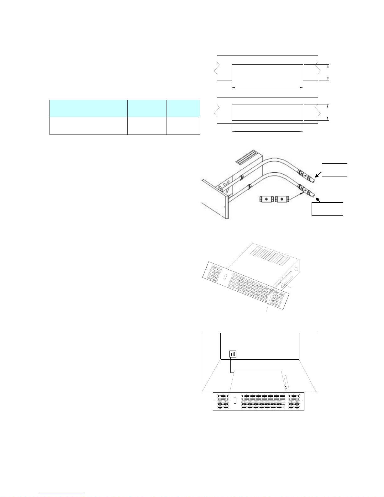
1. The heater should be installed by a qualified
plumber. We recommend the use of a knee pad
when installing this product. Cut the opening in
the plinth to the size shown in the table. Use
method A or B.
Model
Width A
Height
B*
KPH
1300/1500/1800/2100
462mm
97mm
* The overall height of the grille is 100mm. Use
care when cutting the opening.
A
A
B
B
2. Fit isolating valves (not supplied) to the
system flow and return pipes. Failure to fit
isolating valves may mean that the
product is not serviceable in the event of
failure. Remove and discard the two
protection bungs in the copper pipes and
connect the flexible hoses between
system pipework and heater. Open the
isolating valves and check for leaks.
N.B. either pipe may be used on flow or return.
3. Vent air through bleed screw if
necessary.
Flate heat
screw driver
Bleed Valve
I
O
II
4. Isolate electrical supply and
connect the heater electric cable to
the fused spur (3A). Ensure the
fused spur is not directly above the
heater and is accessible after
installation is complete. Electrical
works should be carried out by a
qualified electrician, in compliance
with local regulations.
I
O
II
Fused Spur
Flow
Return

3
Commissioning:
Fault Finding:
1. Turn on the electrical supply at the fused spur.
2. Set the switch to either l or ll.
3. Turn on the central heating system.
4. Set any room thermostat/s to maximum.
5. Set the switch to l –the fan should run and
heat will flow within a few minutes if water
temperature in the system is more than 40°C.
6. Balance the central heating system if Kitchen
plinth heater is installed on the same circuit as
panel radiators.
7. When the installation is working correctly,
remember to reset any room thermostat/s to its
normal setting
1. Fan does not run on any
switch setting.
a). Check the power supply is switched ON.
b). Check fuse in fused spur.
c). Check the wiring connections at the fused spur.
2. No heat output on settings l
and ll.
a). Check the power supply is switched ON.
b). If fitted, ensure any room thermostats are calling for heat.
c). Balance the central heating system if installed on same circuit
as panel radiators and increase the circulating pump speed if
required.
d). Increase the boiler water temperature.
5. Position heater, making sure the
flexible hoses is not kinked and the
electrical cable is not snagged.
Note: Please make sure to remove
the polystyrene under the fan motor
on the back side of the unit
Electrical Cable
Plinth
HOSE
BEND RADIUS
60mm MIN
6. Fix the heater to plinth
using fixing screw holes
located at either end of grille.
I
O
II
Grille to plinth securing
screws
4
Electrical Connections:
The wires in the mains cable are colored in accordance with the following code:
Earth: Green and Yellow
Neutral: Blue
Live: Brown
Note: Please make sure that this unit is earthed.
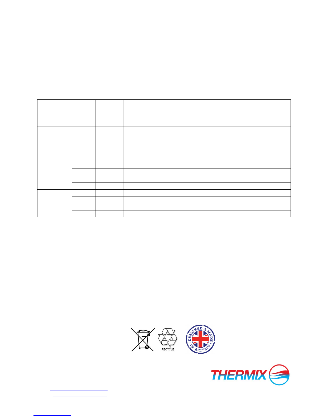
Product Performance Table:
Model
Speed
Output @
75°C
( watts)
Output @
70°C
( watts)
Output @
65°C
( watts)
Output @
60°C
( watts)
Output @
55°C
( watts)
Output @
50°C
( watts)
Output @
45°C
( watts)
KPH-1300B
Low
1411
1305
1200
1010
880
700
495
KPH-1500C
Low
1405
1260
1181
1040
850
701
490
High
1545
1450
1341
1212
1002
801
583
KPH-1800C
Low
1611
1505
1382
1235
993
738
513
High
1855
1702
1591
1457
1233
840
624
KPH-2100C
Low
1925
1669
1472
1386
1227
1039
937
High
2153
1861
1717
1556
1352
1270
1032
KPH-1500W
Low
1405
1260
1181
1040
850
701
490
High
1545
1450
1341
1212
1002
801
583
KPH-1800W
Low
1611
1505
1382
1235
993
738
513
High
1855
1702
1591
1457
1233
840
624
KPH-2100W
Low
1925
1669
1472
1386
1227
1039
937
High
2153
1861
1717
1496
1352
1270
1032
Warranty:
Products with this symbol (crossed out wheelie bin) cannot be disposed as household waste. Old electrical and electronic equipment must be recycled at a
facility capable of handling these products and their waste by-products. If you are purchasing replacement equipment your retailer may offer a 'take back'
scheme, or will be able to give details of the nearest approved authorised treatment facility. Proper recycling and waste disposal will help conserve
resources whilst preventing detrimental effects on our health and the environment.
This product is covered by a standard 12 month product replacement warranty against any manufacturing defects
or workmanship. Warranty is only for the main product not for any accessories that comes with the heater.The
manufacturer reserves the right to replace or repair the product.To extend your warranty to 24 months the product
must be registered online within 28 days from purchase date. See the warranty instruction note included for more
details.
This warranty will not cover:
Necessary maintenance and repair or replacement of parts due to normal wear and tear.
Transport costs, labour cost related to commissioning/decommissioning the product from the central heating
system.
Any damage resulting from modifications or adjustments which may be made to the product.
Thermix UK Ltd
The North Colchester Business,
340 The Crescent, Colchester, CO4 9AD
web www.kitchenheaters.co.uk
email: technical@thermix.co.uk
This manual suits for next models
6
Table of contents
Other Thermix Heater manuals


Popular Heater manuals by other brands


EINHELL
EINHELL MR 920/1 operating instructions

Toyotomi
Toyotomi Sunstream II Type A user guide

Grill'D
Grill'D Dubravo mini Short Installation and operation manual

Heatzilla
Heatzilla SY-CLQ10 user manual

Dimplex
Dimplex WFC 3NB Installation and operating instructions

Sovelor
Sovelor TITAN 155 instruction manual