Thermo Electron LOR772 User manual

Thermo Electron Corporation
Hospital for Sick
Children CatX
Workstation
LOR772 System User Guide

Copyright © October 2006, Thermo CRS, Ltd.
POLARA, ActiveRobot, RAPL-3, RAPL-II, and RAPL are trademarks of Thermo CRS, Ltd. and may be used to
describe only Thermo CRS products.
All brand names and product names used in this guide are trademarks, registered trademarks, or trade names of
their respective holders.
The information in this document is subject to change without notice.
Thermo CRS makes no warranty of any kind with regard to this material, including, but not limited to, the implied
warranties of merchantability and fitness for a particular purpose. Thermo CRS assumes no responsibility for any
errors that may appear in this document. Thermo CRS makes no commitment to update nor to keep current the
information contained in this document.
Thermo CRS software products shall remain the property of Thermo CRS, Ltd.
Additional copies of this guide, or other Thermo CRS literature, may be obtained from the Sales Department or
from your distributor.
Packard, Evolution and PlateStak are trademarks and WinPREP is a registered trademark of PerkinElmer Life
Sciences.
Thermo Electron Corporation LOR772 System User Guide 1
Preface to This Guide
This guide describes how to operate the Hospital for Sick Children CatX
Workstation when it is in the POLARA configuration. See “Workstation
Configurations” on page 1-4 for a descriptions of the configurations.
Who Uses This Guide This guide is for operators of the Hospital for Sick Children CatX
Workstation. This guide assumes the reader has been trained on the safe
operation of the system by Thermo Electron Corporation Laboratory
Automation and Integration. This guide is not intended as a self-teaching
tool.
How to Use This
Guide
This manual is task-based and uses navigational aids to help you quickly
find the topics and information you need.
Before following instructions in a section, read the entire section first.
This guide consists of the following chapters:
•“Introducing the System” which introduces the system and provides an
overview of its basic components.
•“Safe Use of the System” which describes safety directives with which
you and all operators of the system must be familiar.
•“Using the System” which describes requirements that must be met and
tasks that must be performed outside of the POLARA operating
environment.
•“Maintaining the System” which describes periodic inspection, cleaning,
and maintenance.
Note: Throughout this manual warnings are marked by a "!" symbol in the
left margin. Failure to comply with these warnings can result in system
errors, memory loss, damage to the robot and its surroundings, or injury to
personnel. ▲

Preface
2LOR772 System User Guide Thermo Electron Corporation
•“Troubleshooting” which describes system-level troubleshooting
procedures, instructions for contacting Thermo Electron customer
support, and references to other documentation.
•“Index” which contain an index to subjects in this guide.
Units Used in This
Manual
Throughout this manual, measurements are given in Metric SI units.
For More Information This manual contains the information you need to operate the system as a
whole. For details on using the POLARA software to develop methods, and
schedule and perform runs, see the POLARA 2.3 user guides.
Training We offer courses at our facility in Burlington, Ontario Canada, or on-site at
your facility. For more information, contact the Thermo Electron Customer
Support Group.
Contacts You can contact Thermo LAI personnel in any of the following ways.
Surface Mail/Shipping Thermo Electron Corporation
Laboratory Automation and Integration
5344 John Lucas Drive
Burlington, Ontario L7L 6A6
Canada
Telephone 1-905-332-2000 (voice)
1-800-365-7587 (voice: toll free in Canada and United States)
1-905-332-1114 (facsimile)
E-Mail Sales: sales.labautomation@thermo.com
General: info[email protected]
World Wide Web www.thermo.com

Thermo Electron Corporation LOR772 System User Guide iii
Contents
Chapter 1 Introducing the System .................................................................. 1-1
System Instruments and Peripherals ........................................ 1-2
Workstation Configurations................................................. 1-4
System Components .............................................................. 1-6
Power Input Requirements................................................... 1-8
Fuse and Circuit Breaker Requirements ............................... 1-9
Environmental Conditions................................................. 1-10
Master Control Panel............................................................ 1-11
POLARA System Software.................................................... 1-13
CRS DataHandler Software .................................................. 1-14
Chapter 2 Safe Use of the System .................................................................. 2-1
Built-in Safety Features ........................................................... 2-2
Ensuring Safe Use of the System ............................................. 2-3
Operating the System Safely.................................................... 2-5
Understanding Warnings and Error Messages ...................... 2-6
Warnings .......................................................................... 2-6
Error Messages .................................................................. 2-6
Triggering an E-Stop............................................................... 2-7
Adding E-Stops to the System................................................. 2-9
Chapter 3 Using the System............................................................................. 3-1
System Requirements .............................................................. 3-2
Air Supply............................................................................ 3-2
Electric Power ...................................................................... 3-2
User Capabilities .................................................................. 3-2
Bringing the System Online .................................................... 3-3
Taking the System Offline ...................................................... 3-5
Selecting the Computer to Operate......................................... 3-6
Starting a Run......................................................................... 3-7
Chapter 4 Maintaining the System................................................................. 4-1
Lockout/Tagout Procedures .................................................... 4-2
Monthly Maintenance............................................................. 4-3

Contents
iv LOR772 System User Guide Thermo Electron Corporation
Chapter 5 Troubleshooting...............................................................................5-1
Recovering from a Mover Collision......................................... 5-2
Getting Help........................................................................... 5-3
Preparing to Contact Thermo Electron................................ 5-3
Gathering Problem Data...................................................... 5-4
Capturing System Error Messages ........................................ 5-5
Capturing Text ................................................................. 5-5
Capturing Graphics........................................................... 5-6
Contacting Thermo Electron Customer Support ................. 5-7
Index ...................................................................................................I-1

Thermo Electron Corporation LOR772 System User Guide v
Figures
Hospital for Sick Children CatX Workstation layout ..............1-2
The Master Control Panel (MCP) .........................................1-11
MCP controls ........................................................................1-11
POLARA provides a graphical user interface ......................... 1-13


Thermo Electron Corporation LOR772 System User Guide vii
Tables
Instrument usage by configuration ........................................................... 1-4
Controller input power ratings ................................................................. 1-8
CatX environmental requirements .......................................................... 1-10
Computer and Belkin Port Number mapping .......................................... 3-6


Thermo Electron Corporation LOR772 System User Guide 1-1
Chapter 1 Introducing the System
The Hospital for Sick Children CatX Workstation station is a modular and
expandable system for high throughput screening.
This chapter introduces the system and provides an overview of its basic
components. It includes the following topics:
•“System Instruments and Peripherals” on page 1-2
•“System Components” on page 1-6
•“Master Control Panel” on page 1-11
•“POLARA System Software” on page 1-13
•“CRS DataHandler Software” on page 1-14
Introducing the System
System Instruments and Peripherals
1-2 LOR772 System User Guide Thermo Electron Corporation
System Instruments
and Peripherals
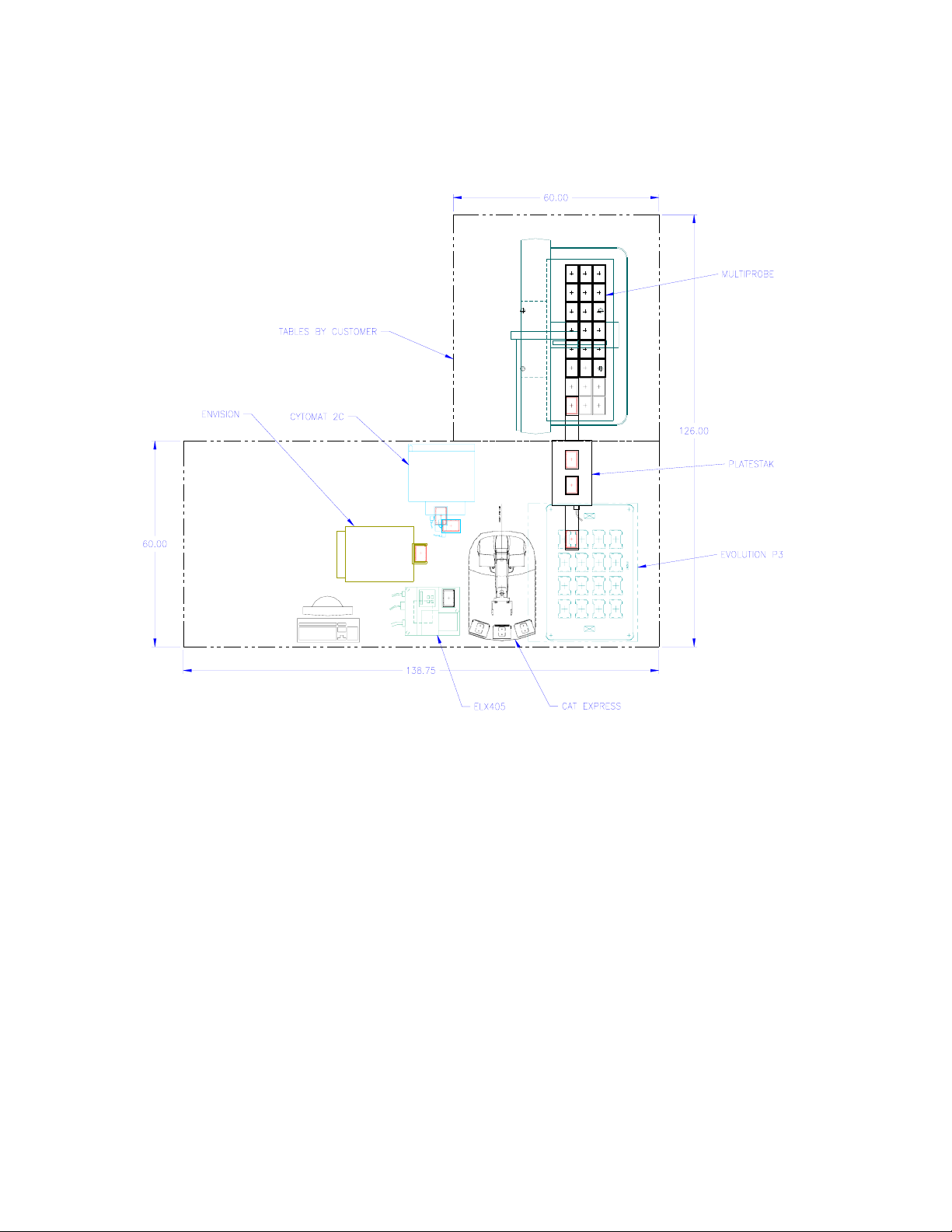
The Hospital for Sick Children CatX Workstation system includes the
following instruments and peripherals:
Figure 1-1. Hospital for Sick Children CatX Workstation layout
• One Thermo CRS Regrip station (built in to CatX base)
• One Thermo CRS Lidder
• One Thermo Cytomat 2 incubator
• One MicroScan MS-3 Bar Code reader
• One PerkinElmer Evolution P3 liquid handler
• One PerkinElmer Envision reader
• One PerkinElmer Multiprobe pipettor (note: this instrument is not
integrated into the POLARA workspace)

Introducing the System
System Instruments and Peripherals
Thermo Electron Corporation LOR772 System User Guide 1-3
• One PerkinElmer PlateStak storage unit
• One Biotek ELx405 washer
The system uses an Articulated Robot mover controlled by the POLARA
scheduling software, to move microtitre plates between instruments. For
details on the components of the system, see “System Components” on
page 1-6.
For details on the operation of the instruments, refer to the user guides
supplied with the instrument.

Introducing the System
System Instruments and Peripherals
1-4 LOR772 System User Guide Thermo Electron Corporation
Workstation
Configurations
Thermo personnel have integrated this workstation into two configurations:
• A POLARA system consisting of all instruments except the PE
Multiprobe.
• A WinPREP system consisting of the PE Evolution, Multiprobe, and
PlateStak.
The instruments that can be used in each configuration are shown in
Table 1-1.
The two configurations can be used at the same time only when POLARA is
running a method whose profile does not include the PlateStak and
Evolution.
This document provides user information for operating the POLARA
configuration only.
To setup a configuration, follow these procedures:
To setup a POLARA configuration 1. If the PlateStak is in the profile selected for your POLARA method,
change the PlateStak serial port switch so POLARA can communicate
with the PlateStak.
2. If the Evolution is in the profile selected for your POLARA method,
ensure that its scripts used in POLARA methods do not access the 4
nests closest to the PlateStak diving board.
3. Ensure the Evolution P3 pipe server is running on the Evolution
computer.
Table 1-1. Instrument usage by configuration
POLARA only Common instruments WinPREP only
Thermo Cytomat 2 incubator PE Evolution PE Multiprobe
PE Envision reader PE PateStak
Biotek ELx405 washer
MicroScan MS-3 Bar Code reader
Thermo CRS Lidder
Thermo CRS Regrip station

Introducing the System
System Instruments and Peripherals
Thermo Electron Corporation LOR772 System User Guide 1-5
4. Ensure the EnVision pipe server is running on the Envision computer.
5. Continue using the POLARA configuration as described in Chapter 3:
“Using the System”.
To setup a WinPREP
configuration
1. If POLARA is running, ensure it is not running methods whose profile
includes the PE Evolution and PlateStak.
2. Change the PlateStak serial port switch so that WinPREP can
communicate with the PlateStak.
3. Continue using the WinPREP configuration on the WinPREP
computer according to PerkinElmer requirements.

Introducing the System
System Components
1-6 LOR772 System User Guide Thermo Electron Corporation
System Components Each system consists of the following main components:
• Tables, which are customer supplied.
• The system computer, which runs the POLARA software that provides
high-level control of all hardware in the system and which collects the
data gathered during runs. Each instrument on the table is connected to
the system computer through a serial port or via the system LAN.
The system computer also runs application software provided by the
manufacturers of the instruments in the system.
Some systems use one or more additional computers to run application
software and to communicate with selected instruments. All computers
are connected through a LAN.
• The container transport consists of the following components:
• The Articulated Robot holds containers using gripper fingers and
moves the containers between instruments. Articulated robots
consist of ‘linked joints’ that rotate or slide to change the location of
its gripper.
• The C500C controller directs the motion of the robot arm and
provides power and safety circuits. The controller is built into the
base of the CataLyst Express.
Note The container transport also includes an E-Stop circuit into which
instruments can be integrated. ▲
• The serial expander provides an interface through which instruments
can perform serial communications with the system computer.
• The GPIO expander provides an interface through which the system
computer can control digital outputs and respond to digital inputs. For
example, an instrument with automatic doors can be interfaced through
the GPIO expander, enabling the system computer to open and close
the doors, and determine when the doors are open or closed.
• The Master Control Panel provides the system operator with an E-Stop
button with which to cut power to the moving components in an
emergency, and system and motor power status and reset buttons.
Your AR system may also include the following components:

Introducing the System
System Components
Thermo Electron Corporation LOR772 System User Guide 1-7
•Asystem LAN hub, into which the network interfaces of the
controllers, the system computer, and possibly some instruments are
connected.
•ABelkin KVM Switch that enables the system keyboard and display to
operate computers in the system LAN.
•Uninterruptible power supplies (UPS), which provide continuous
power to the system. If an interruption occurs in the main power
supply, the UPSs maintain power for up to 30 minutes.
•Guarding, consisting of plexiglass barriers that block access to moving
parts of the transport.
For details about Dimension4 components, see the following topics:
•“Power Input Requirements” on page 1-8
•“Fuse and Circuit Breaker Requirements” on page 1-9
•“Environmental Conditions” on page 1-10

Introducing the System
System Components
1-8 LOR772 System User Guide Thermo Electron Corporation
Power Input Requirements Controllers require the power inputs listed in Table 1-2.
Table 1-2. Controller input power ratings
Description Rating
Input voltage 110/115/230 VAC, ±10%
Line frequency 50-60 Hz
WARNINGThe controller must be grounded! The AC cord supplied with
the controller provides the proper grounding terminal. Do not cut off the
third terminal from the AC cord set. ▲

Introducing the System
System Components
Thermo Electron Corporation LOR772 System User Guide 1-9
Fuse and Circuit Breaker
Requirements
Refer to the C500C Controller User Guide or the CataLyst Express User Guide
for fuse and circuit breaker requirements of AR controllers.

Introducing the System
System Components
1-10 LOR772 System User Guide Thermo Electron Corporation
Environmental Conditions The CatX requires the environment conditions shown in Table 1-3.
Table 1-3. CatX environmental requirements
Environment Condition Requirement
Relative humidity Below 50%, non-condensing
Temperature 10-40 °C
Ventilation A minimum of 11.5 cm (4.5 in.) clearance between the
grills at the rear of the controller and your enclosure
Atmosphere Clean, low dust; dry office/lab environment
Installation location for INDOOR use only
Table of contents


