Thermo Electron 8600 Series User manual
7998600 Rev. 4
ii
The material in this manual is for information purposes only. The contents and the product it describes
are subject to change without notice. Thermo Electron Corporation makes no representations or
warranties with respect to this manual. In no event shall Thermo be held liable for any damages, direct
or incidental, arising out of or related to the use of this manual.
MANUAL NO. 7998600
4 FR-1789 6/27/05 Revised VRP troubleshooting section for Release 3 aks
3 22216 3/22/04 Added 120V 23 cu. ft. units aks
2 22179 2/24/04 Revised electrical schematic, start capacitor part number aks
-- 8/21/03 Door gap, high stage revisions aks
-- 8/13/03 Revised compressor information page B-1 aks
-- 6/27/03 Revisions per A. Thomas aks
1 21605 5/29/03 Wrong power alarm modifications aks
0 3/21/03 New manual aks
REV ECR/ECN DATE DESCRIPTION BY

iii
Table of Contents
Section 1 – General Operation
1.1 Initial Start Up......................................1-1
1.2 Equipment Explanation.........................1-1
1.3 Operating Pressure
“High and low stage systems”...............1-1
Section 2 – Troubleshooting Charts
2.1 Probe 1,2,3, and 4 failure alarm
(Single) ...............................................2-1
2.2 Probe 1,2,3, and 4 failure alarm
(All probes)..........................................2-1
2.3 Unit will not communicate with alarm
system .................................................2-2
2.4 Display/Keyboard not functioning .......2-3
2.5 Door ajar alarm....................................2-4
2.6 No door access ....................................2-5
2.7 Low battery alarm................................2-6
2.8 Noise ...................................................2-6
2.9 Hot condenser alarm ............................2-7
2.10 High stage system failure alarm ...........2-8
2.11 Power failure alarm..............................2-9
2.12 Wrong power.......................................2-10
2.13 Low Temperature.................................2-10
2.14 High temperature alarm or system not
maintaining temperature ......................2-11
2.15 Troubleshoot compressor.....................2-13
2.16 Voltage Compensation Failure.............2-14
Section 3 – Charts and Schematics
3.1 Analog Output Reference Table.............3-1
3.2 RTD Temperature vs. Resistance ...........3-2
3.3 Pressures vs. Cabinet Temperature.........3-3
3.4 Refrigeration Schematics.......................3-4
3.5 Electrical Schematics ............................3-6
3.6 Micro Board ..........................................3-8
3.7 High Voltage Board...............................3-8
Section 4 -Hidden Functions
4.1 Hidden Test...........................................4-1
4.2 Hidden Calibration ................................4-2
Appendix A - Glossary
Glossary of terms ........................................A-1
Appendix B
Compressor Information..............................B-1

1 - 1
General Operation
1.1 Initial Start Up
1. Power Switch on.
2. Cabinet temperature 0.5°C or warmer than set point.
3. Fans 1 and 2 turn ON.
4. High stage compressor turns ON, after ten seconds delay.
5. Low stage compressor turns ON when:
A. Thirty seconds after high stage starts and heat exchanger probe reads
–41°C or colder or
B. Five minutes after high stage starts and heat exchanger probe reads
between –33°C to –40°C.
If heat exchanger probe warms-up to –20°C or warmer, the low stage
compressor shuts down until either condition 5A or 5B is met. After thirty
minutes, if condition 5A or 5B is not met, the high stage system failure will be
activated.
6. Once the cabinet temperature reaches –50°C, the*expansion tank solenoid is
opened (de-energized). The vacuum relief heater and mullion heater on double
door units, are energized and operate continuously until the cabinet is warmer
than –50°C.
7. Set point achieved, fans and compressors cycle off.
8. Steps 2 though 7 repeat (cycle).
*Items or functions unique to this system
1.2 Expansion Tank Assembly and Solenoid Valve
Location: Suction side of low stage system.
Purpose: Tank assembly increases low stage system refrigeration
capacity. Prevents excessive low stage pressures at
temperatures warmer than –50°.
Operation: The tank assembly solenoid valve is normally open. The
solenoid valve is energized (closed) when the control probe
senses temperature warmer than –50°C. The solenoid valve is
de-energized (open) when the control probe senses
temperature colder than –50°C.
1.3 Operating Pressure “High and low stage systems”
The suction side pressure for both systems typically runs in a vacuum. Prior to
opening a system for a pressure reading, always purge your lines according to the
manufacturer’s recommended procedure. For further information, call Thermo Forma
Service Department.
230 Volt Freezers
Only the compressors require 230 volts. The remaining high voltage components
operate using 115 volts.

2 - 1
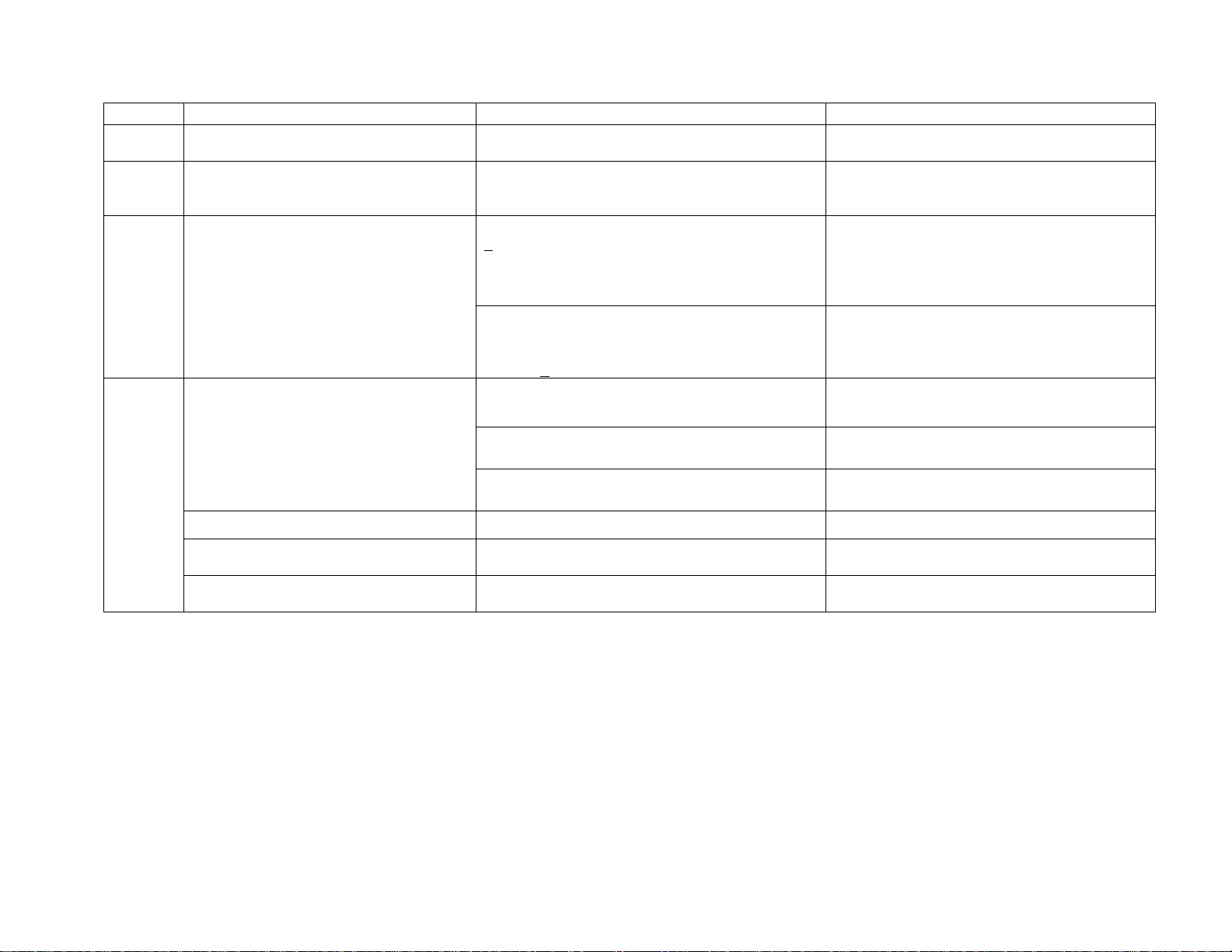
2.1 Symptom: Probe 1, 2, 3, or 4 Failure Alarm - SINGLE PROBE FAILURES
Order Possible Cause Verification Action
Probe
Unplugged. Re-seat connector. Re-seat all connections.
1
Not fully seated Verify wires are fully seated in connectors and
connectors are seated together
Replace probe if necessary.
Bad probe
Short.
Open. Display reads 99. Verify probe resistance. See
Temperature vs. Resistance Chart (Page 3-2).
Replace probe.
2
Wrong value. Verify probe resistance. See Temperature vs.
Resistance Chart (Page 3-2).
Replace probe.
3 Micro board.
Temporarily switch suspect probe with control or
heat exchanger probe.
If the same error exists, replace micro board.
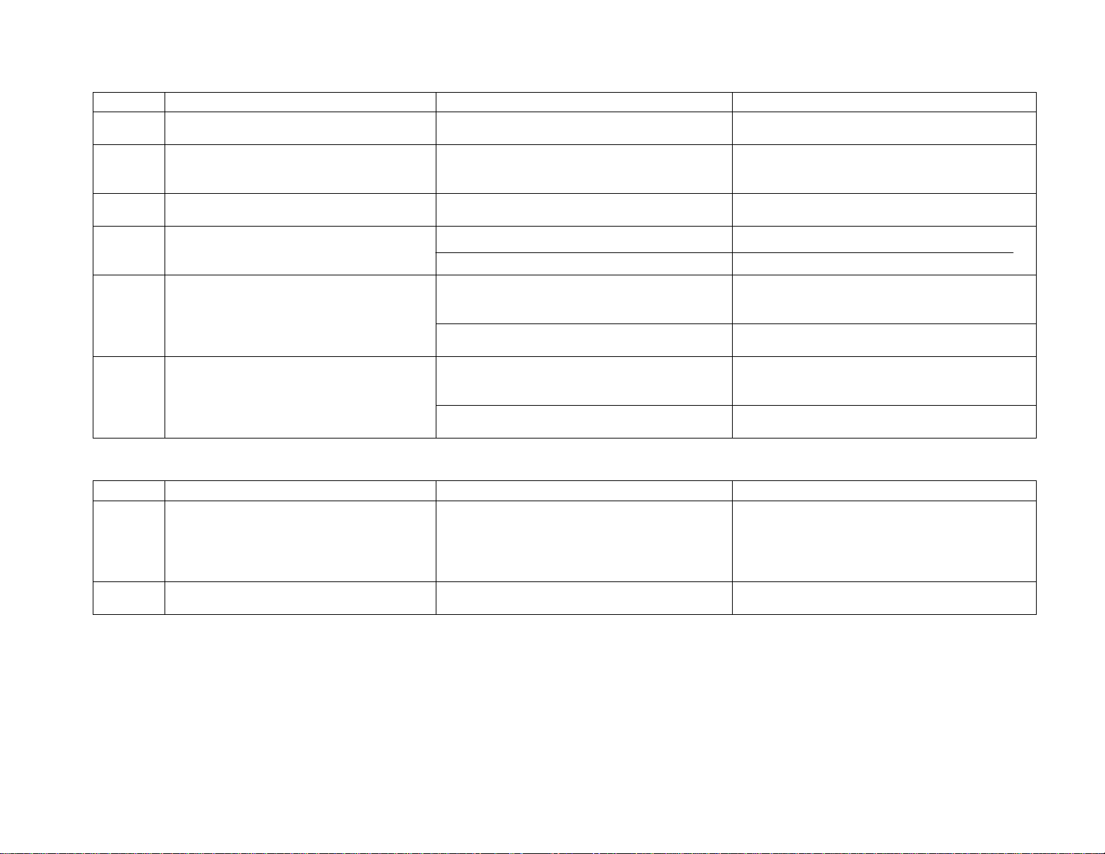
2.2 Symptom: Probe 1, 2, 3, and 4 Failure Alarm – (ALL PROBES FAIL)
Order Possible Cause Verification Action
Re-seat connector.
1 Control probe not installed.
Startup only.
Verify wires are fully seated in connectors and
connectors are seated together.
Reinitialize (re-start) unit.
Reseat all connections.
Replace probe if necessary.
Bad control probe Display reads 99. Bad control probe will also
cause a high temperature alarm and lock both
compressors on.
2
Short.
Open.
Wrong value.
Verify probe resistance with Temperature vs.
Resistance Chart (page 3-2).
Replace probe.
3 Micro board.
Temporarily switch control probe with heat
exchanger probe.
If the same error exists, replace micro board.
4 Micro board EEPROM Problem still exists after re-initializing unit. Re-initialize eeprom in test mode. If problem
remains, replace the micro board. Note: all
calibration, set points and configuration are set to
default.

2 - 2
2.3 Symptom: Unit will not communicate with alarm system (Remote Alarm Contacts/Analog
System/Serial communication)
Order Possible Cause Verification Action
Check that all connections are tight and properly
wired. Missing wires?
Tighten and / or correct wiring.
1 Remote Alarm Contacts
Measure continuity of alarm contacts between
pins 6 & 7 and 6 & 8 while toggling in test mode
(pin 6 is common).
Replace micro board if contacts do not change
state.
Verify the setting is correct in hidden calibration
and corresponds to the dip switch settings on the
micro board per the electrical schematic.
Make changes so the dip switch settings and hidden
calibration settings match.
Measure output. Compare with Analog Output
Reference Table (page 3-1).
Call the factory service department 888-213-1790.
See section 4.2.p Analog Calibration (page 4-3).
2 Analog Output
Check that all connections are tight and properly
wired. Missing wires?
Tighten and / or correct wiring.
Verify address is correct in configuration menu
and matches the 1535 address.
Change so that the unit address of the freezer
matches the 1535 address.
Verify the setting is correct in hidden calibration
and corresponds to the dip switch settings on the
micro board per the electrical schematic.
Make changes so that the dip switch settings and
hidden calibration settings match.
Check that all connections are tight and properly
wired. Missing wires?
Tighten and / or correct wiring.
Tighten and / or correct wiring.
3 Serial Communication
Verify that the cable is a DB9 (straight through)
extension cable.
Replace cable if necessary.

2 - 3
2.4 Symptom: Display / Keyboard Not Functioning
Order Possible Cause Verification Action
1 Turned battery on before AC power is
applied.
(initial start up issue only)
Ask customer/end user. Turn unit power off. Turn battery off. Reapply AC power
before the battery is turned on.
2 No AC power and no battery power. Verify supply AC voltage is present.
Supply correct line voltage.
+14VDC on switching power supply.
If not, replace switching supply.
+14VDC on micro board at connector
labeled DC power from HV board (pins 1
and 6).
Check connector seating on ribbon cables. Replace if
required.
3 Micro board -
Micro LED LD1 on micro board not
functioning.
Is unit operating (fans, compressors)?
If no, replace micro board.
If yes, continue to step 4.
Turn unit off, then turn unit back on.
Miscellaneous characters displayed. Replace display board.
4 Micro board - Micro LED LD1
functioning / no display LED LD2.
Check connection of 25 pin D sub cable
at both ends.
Waiting Comm is displayed. Replace micro and/or display as
needed.
Display -
Missing segment Visual. Replace display board.
Keys not responding
Check continuity for buttons on overlay. Replace overlay.
LEDs not functioning
Ohm out LEDs.
Replace overlay.
5
No Alarm Press any key on overlay. If no audible, replace display board.

2 - 4
2.5 Symptom: Door Ajar Alarm
Order Possible Cause Verification Action
1 No magnet Visually inspect for magnet in door handle. Replace magnet as required.
2 Worn door handle
Inspect inside of door latch for signs of metal
(aluminum) wear (wobbly handle).
Replace latch if necessary and verify vacuum relief
port operation, as well as the door alignment.
Improper connection
Wires loose from door switch connector.
Verify wires are properly seated in connector.
If required, re-seat the wire connection.
Door switch connector not seated to board
connector.
Verify connectors are seated together.
Re-seat connection.
3
Installed in wrong connector Verify the plug is in the correct receptacle.
Re-seat plug in correct receptacle.
4 Improper door alignment Verify door gap. Single door .600”
Double door .700”, both measured from the hinge
side.
Make adjustment as required.
5 Bad door switch
Verify continuity on door switch by opening and
closing door.
If no continuity of switch during opening and
closing of door, replace door switch.
6 Defective micro board. Short out door switch connector. If alarm does not clear replace micro board. Or else
repeat starting at Step 1.
2 - 5
2.6 Symptom: No Door Access
Order Possible Cause Verification Action
1 Door locked. Check to ensure door is not locked. Unlock door.
2 Vacuum relief assembly is frozen over.
Visually inspect vacuum relief port for any
restrictions. Clean as necessary. Follow routine maintenance
instructions in user’s manual to periodically clean
the port.
Check voltage at J7 on the display board for +14V
+0.5?
YES (+14V): unplug heater harness from PCB and
measure resistance across heater leads. Heater
resistance should be between 9 and 30 Ohms.
If not between 9 and 30 Ohms, replace VRP
assembly.
3 Release 3 unit: Vacuum relief not
functioning.
Release 3 units(built after 6/2005 have
vacuum relief port in door.
NO: Check and reseat connections on heater harness.
Measure DC voltage at the switching power supply.
On the 6 pin connector, measure between pins 1 and
6 (+14V + 0.5V)
Check and reseat connectors between switching
power supply and high voltage board. Also check
and reseat connections between high voltage
board and micro board.
Verify unit is colder than –50°C. Cabinet temperature must be colder than –50°C to
activate vacuum relief heater.
90-130VAC at heater?
YES: Ohm out heater. Heater to be 1037-1210 Ohms Replace heater if required.
Release 1 unit: Vacuum relief not
functioning.
Release 2 units built between May 2003
and June 2005 do not use a heated vacuum
relief assembly.
NO: Check connections Re-seat connection(s). If problem still exists,
continue troubleshooting.
Blown fuse Check fuse. Ohm out fuse, replace fuse as required.
Micro board Check voltage between U16-13 and J11-1 on micro
board. If voltage is greater than 10VDC, replace micro
board.
High voltage board. Check DC voltage across D15 on high voltage. If voltage is less than 10VDC, replace high
voltage board.

2 - 6
2.7 Symptom: Low Battery Alarm
Order Possible Cause Verification Action
1 New battery / new unit or freezer just placed
into service?
Ask customer/end user.
Complete steps 2,3, & 4.
If yes, batteries required 36 hours for charging.
If no, continue to step 5.
2 Missing battery Visually look for battery. Install battery.
3 Battery switch turned off. Verify switch is “on”.
Turn switch on after AC power is applied.
4 Connection –
Wires making connection.
Battery wired backwards.
Ensure connections are tight at the battery,
battery switch, and micro board. Verify the red
wire is connected to the positive terminal.
Tighten and change wiring as needed.
5 Battery switch defective. Verify continuity with multimeter. Replace switch.
6 Battery Calibration Measure voltage at the battery and compare to
the value displayed in hidden calibration.
Match values.
7 Battery voltage < 12.1 during battery test. Check voltage at the battery during battery test
after 2 days (48 hours) of operation.
If voltage < 12.1, replace battery and continue to
step 8.
8 Micro board –
Battery test circuit.
Battery charging circuit
Disconnect battery and measure voltage at the
battery wires.
If 13.5 - 13.8 VDC is present, replace battery.
If not present replace micro board and battery.
2.8 Symptom: Noise
Order Possible Cause Verification Action
1 Loose screws on panels or compressors. Ensure all screws and bolts are tightly secure. Tighten as needed.
2 Missing or no sound insulation.
Remove side panels to ensure insulation is
present. Inspect the bottom of cabinet to verify
insulation is present.
Add foam panels if necessary.
3 Start capacitor on compressor.
Ensure capacitor is not touching the compressor
body and capacitor bracket securely holds the
capacitor.
Adjust as needed.
4 Electrical cover on compressors.
Ensure cover is tight.
Tighten as needed.
5 Vibrating refrigeration lines.
Inspect for lines that are touching. Adjust as necessary.
6 Solenoid Ensure that the solenoid base sits on presstite tape
and is tie wrapped to the freezer base.
Replace presstite tape and tie wraps, if necessary.

2 - 7
2.9 Symptom: Hot Condenser Alarm
Order Possible Cause Verification Action
1 High ambient.
Measure ambient temperature.
Is ambient above 33°C?
Alarm will cycle with compressors. If ambient is
above 37°C, alarm is on constantly.
Move to cooler location / lower ambient.
Educate customer.
Check filter. Change / clean filter.
Check for condenser blockage. Remove blockage.
Verify clearance specifications of 5 inches are
met.
Install stand-offs.
2 Restricted / reduced airflow.
Check for open front panel.
Close front panel.
Confirm High stage is on (fans should be running) Start unit to continue, if off.
Identify problem fan(s) Method ( tie wrap…)
If no voltage, check voltage between U13-10 and
J11-1, U16-10 and J11-1 on micro board. If less
than 10VDC, replace micro board. Else if DC
voltage across D11 and D14 on high voltage board
is less than 10VDC, check ribbon cable. If ribbon
cable OK, replace high voltage board.
3 Fan(s) not running.
Confirm voltage to each fan by verifying voltage
at pins J29-1 to J29-7 and J29-2 to J29-8 on the
high voltage board.
If voltage exists, measure Ohms for fans at
connector that plus into J29 on high voltage board.
First column of black wires for fan in front of high
stage, second column of black wires for fan in front
of low stage. Ohms should be 130 to 145 in 23°C.
Replace fan(s) with improper Ohms.
4 Defective probe. See: Probe 1,2,3, or 4 failure alarm
troubleshooting chart. Condenser probe plus into
J4 of micro board.

2 - 8
2.10 Symptom: High Stage System Failure Alarm
Order Possible Cause Verification Action
1 Clear HS System Failure Alarm in Configuration
Mode.
2 Fan(s) not running.
See procedure for troubleshooting fans under “Hot
Condenser” alarm.
High stage compressor not starting or not running.
Inadequate power at the customer’s
site.
Check voltage at the wall and monitor for large
voltage drop during start-up.
If voltage drops below 90V for 120V units or 180V for 230V
units, contact customer.
No voltage at compressor. LD2 and LD4, on high
voltage board, are not on.
Line voltage is within specified limits
For LD2 measure voltage between U13-12 and J11-1, for LD4
measure voltage between U13-14 and J11-1, on micro board. If
voltage is less than 10VDC, replace micro board.
If voltage is greater than 10VDC, for LD2 measure voltage from
right side of D3 to right side of D4, for LD4 measure from right
D7 & right side of D8 on high voltage board. If voltage is less
than 10VDC, check ribbon cable. Ribbon cable OK, replace
high voltage board.
No voltage at compressor, LD5 (HS) on high
voltage board is on.
Check connections: enclosure, high pressure cutout switch. Ohm
out pressure switch. Switch to be closed. Switch OK, measure
voltage between pins 4 and 5 of J30. If no voltage, replace high
voltage board.
Switch defective; jumper around switch and continue to test.
No voltage at compressor LD5 (HS) is off and
should be on.
If voltage between U13-15 and J11-1, on micro board, is less
than 10VDC, replace micro board.
Else, if DC voltage across D12 on high voltage board is greater
than 10VDC, check ribbon cable. If ribbon cable OK, go to
previous verification.
Else, if D12 voltage less than 10VDC, replace high voltage
board.
AC power to high stage compressor.
If required, go into test mode; turn
both fans and high stage compressor
on.
Voltage at compressor Check continuity of compressor thermal switch.
Check winding resistance of compressor.
See Appendix B
Check compressor-starting hardware. Replace parts as needed.
3
HS compressor cycles on high-
pressure cutout.
Install pressure gauges on high stage and verify
that high-pressure cutout is functioning normally.
Replace defective high-pressure cutout.
4 HX probe reading incorrectly.
Compare T/C reading on interstage heat exchanger
to resistance of HX probe and display value. See
Resistance to Temperature Chart (page 3-2).
If T/C differs from resistance and displayed value, defective
probe. If displayed value differs from T/C and resistance value,
replace micro board.

2 - 9
2.10 Symptom: High Stage System Failure Alarm (continued)
Order Possible Cause Verification Action
5 Restriction in high stage capillary
tube.
Measure the temperature at the heat exchanger.
If a restriction exists, the heat exchanger will be
warmer than normal.
Recondition high stage.
2.11 Symptom: Power Failure Alarm
Order Possible Cause Verification Action
1 Unplugged line cord.
Check that line cord is properly seated in wall
connection and relay enclosure.
Re-attach line cord and install strain relief per
user’s manual, if required.
Verify switch / circuit breaker (power switch) by
continuity or test for line voltage on high voltage
board where wires from switch are connected to
board.
Replace if required.
2 Unit circuit breaker (power switch).
Verify switch / circuit breaker does not trip below
amperage rating.
Replace if required.
If trips above rating, go to step 5.
3 Loose wires
Circuit Breaker/ Power switch.
High voltage board.
Switching power supply.
Verify line voltage connection from circuit
breaker/power switch to high voltage board inputs
and ribbon cable connection from high voltage
board to DC switching power supply.
Seat or replace as required.
4 Defective switching power supply.
Verify input line voltage and output voltage,
+14 VDC, is present at switching power supply.
Replace if required.
5 Damaged components or wiring. Inspect relay enclosure for damaged components
and wiring.
Replace as required.
6 Defective starting hardware or
compressor(s).
Check both stages for L.R.A.
If compressor attempts to run and draws L.R.A.,
check start relay for proper operation and values on
start and run capacitors. Ohm compressor windings
and compare to nominal values (Appendix B).
Dedicated circuit and correct rating? Advise customer.
7 Facility Wiring
Circuit breaker
Wire. Connections, gauge size, and length. Try a different circuit. Fix as required.
2 - 10
2.12 Symptom: Wrong Power
Order Possible Cause Verification Action
1 Sequence that battery and power switch was
turned on (start-up only)
Was battery switch turned on before power switch
was turned on?
Turn both switches off. Turn power switch on, then
turn battery switch on.
2 Facility wiring incorrect.
230V receptacle 115 supply
Proper line voltage. Need correct operation voltage.
3 Wrong line cord set.
Verify correct line cord plug : P5-15 (120V,15A),
P5-20 (120V,20A), P6-15 (230V,15A).
Contact manufacturer.
4 Ribbon cable connection between high
voltage and micro board.
Cables properly seated.
Ribbon cables damaged.
Reseat connections.
Replace cable(s).
Measure AC voltage between left side F1 and left
side of R9. Voltage should be between .25 and .95
VAC.
If incorrect voltage, replace high voltage board.
5 High voltage board failure.
Measure frequency between pins 4 and 5 of U1. Frequency is not twice the frequency of wall outlet.
Replace high voltage board.
Measure AC voltage across R40 on micro board.
Voltage should be between .25 and .95 VAC.
No voltage: replace ribbon cable.
Good voltage: replace micro board.
6 Micro board failure.
Measure frequency between pin 10 of U14 and
pin 8 of U28..
No measurement, check ribbon cable. If ribbon
cable is ok, replace micro board.
2.13 Symptom: Low Temperature Alarm
Order Possible Cause Verification Action
1 Relays on high voltage board not being
turned off.
Verify that LEDs (LD5 and LD6) on the high
voltage board are illuminated and voltage across
D12 and D13 is greater than 10VDC.
IF LD5 and LD6 on and voltage is greater than
10DC, replace micro board. If LD5 and LD6 are
off and voltage is less than 10VDC, replace high
voltage board.
2 Wrong probe value Verify probe resistance with Temperature vs.
Resistance Chart (page 3-2).
Replace as required.

2 - 11
2.14 Symptom: High Temperature Alarm or System is not maintaining temperature
Order Possible Cause Verification Action
Inspect gasket for ice or excessive frost.
Clear ice or frost from door and gasket.
Check door adjustment: fit and gasket
compression.
Adjust door to restore uniform gasket compression.
1 Door
Frequency and duration of door openings and
product loading (size of load and temperature of
introduced product. If customer usage is high or
suspected as high, then verify actual performance
with a datalogger.
Work with customer to communicate effects of
loading.
2 Load – evaluate customer usage. Install thermocouple at control sensor and verify
control RTD temperature is accurate.
Troubleshoot control probe with “Probe 1,2,3 & 4
failure procedure”.
3 Defective control probe
See procedure for troubleshooting probes “Probe
1,2,3 or 4 Failure (Single Probe).
4 Normal relay(s) on high voltage board LD 2 and LD 4 on high voltage board are not lit
120v units: Line voltage 105 - 140
230V/60Hz units: Line voltage 210 - 260
230V/50Hz units: Line voltage 190- 230
Line voltage is within specified limits
For LD2 check voltage between U13-12 and J11-1
on micro board, for LD4 measure between U13-14
and J11-1, if voltage is less than 10VDC, replace
micro board.
If voltage is greater than 10, then check DC voltage
from right side of D3 to right side of D4 (LD2),
from right D7 & right side of D8 (LD4) on high
voltage board. If is less than 10VDC, check ribbon
cable. If ribbon cable OK, replace high voltage
board.

2 - 12
2.14 Symptom: High Temperature Alarm or System is not maintaining temperature (continued)
No voltage at compressor, LD6 (LS) on high
voltage board is on.
Check connections: enclosure, high-pressure cutout
switch. Ohm out pressure switch. Switch to be
closed. Switch OK, measure voltage between pins
1 and 2 of J30. If no voltage, replace high voltage
board.
Switch defective; jumper around switch and
continue to test.
No voltage at compressor LD6 (LS) is off and
should be on.
If voltage between U13-16 and J11-1, on micro
board, is less than 10VDC, replace micro board.
If voltage greater than 10, check DC voltage across
D13 on high voltage board is less than 10VDC,
check ribbon cable. If ribbon cable OK, go replace
high voltage board
If D13 voltage greater than 10VDC, . Go to
previous verification, LD6 maybe defective.
AC power to low stage compressor.
Voltage at compressor Check continuity of compressor thermal switch.
Check winding resistance of compressor.
See Appendix B
Check compressor-starting hardware. Replace parts
as needed.
5
LS compressor cycles on high-pressure
cutout.
Install pressure gauges on low stage and verify
that high-pressure cutout is functioning normally.
Replace defective high-pressure cutout.
6 High stage refrigeration system failure Verify interstage heat exchanger temperature is
above –33°C.
Troubleshoot with “Troubleshooting Compressor”.
7 Low Stage refrigeration system failure Verify interstage heat exchanger temperature is
below –33°C.
Troubleshoot with “Troubleshooting Compressor”.
2 - 13
2.15 Symptom: Troubleshoot compressor
Order Possible Cause Verification Action
Verify compressor starts and run continuously.
If yes, install gauges and go to next step.
If no, go to order 3 of “Compressor starting problem”.
Verify suction pressure is above:
High Stage – 0 psig
Low Stage – 10” vac
If suction pressure is “ok”, proceed to next step.
If suction pressure is below limits, conduct equalization test: if
equalization test fails – blocked cap tube; recondition refrigeration
system.
If equalization test passes, warm unit, go order 2 “unit at room
temp, heat exchanger at room temp”.
Verify discharge pressure is below 175 psig – conduct
efficiency test.
Suspect bad compressor (values): replace compressor…recondition
refrigeration system.
1 Low suction pressure
problem
If discharge pressure is above:
LS 175 psig
HS 250 psig
Suspect non-condensables: recondition the refrigeration system in
question.
Verify static pressures are acceptable. Recondition low stage (suspect partial restriction in cap tube).
Compare high stage static and low stage static
pressures. Are the static pressures on high and low
stages identical?
Yes, replace interstage and recondition both the high and low
stages.
No, go to next verification.
2 Unit at room temperature,
heat exchanger at room
temperature
Static pressure unacceptable. Suspect under- or overcharge. Recondition refrigeration system for
system in question.
Measurements of wall voltage
Unit off
Unit at start-up.
If unacceptable, work with customer to correct.
If acceptable, go to next step.
3 Compressor Starting
Problem
Verify compressor attempts to start (draws L.R.A. or
turns over briefly).
If no attempt to start –
Check voltage to compressor
No voltage at compressor LD5 (HS) or LD6 (LS) is on.
No voltage at compressor LD5 (HS) or LD6 (LS) is
off.
If compressor attempts to run and draws L.R.A., check start relay
for proper operation and values on start and run capacitors.
If voltage at compressor, isolate compressor. Ohm compressor
windings at compressors and compare to nominal values (Appendix
B).
Check connections: enclosure, high pressure cutout switch. Ohm
out pressure switch. Switch to be closed.
Voltage between U13-15 (HS) or U13-16 (LS) and J11-1 on micro
board is less than 10VDC, replace micro board. Else if DC voltage
across D12 (HS) or D13 (LS) on high voltage board is less than
10VDC, replace high voltage board.

2 - 14
2.15 Symptom: Troubleshoot compressor continued
Order Possible Cause Verification Action
Verify if compressor tripping on high pressure switch
and confirm that discharge is reaching 375 psig (+ 25
psi).If tripping on pressure switch and discharge
pressure is high, then troubleshoot why discharge
pressure is high.
If tripping on high pressure switch and pressure is not running at
375 psig (+25), then replace pressure switch.
3
Verify if compressor is tripping on thermal switch. If yes, recondition low stage.
If no, troubleshoot high voltage board (board turning compressor
off).
2.16 Symptom: Voltage Compensation Failure
Turn unit off, and then back on. If unit goes into
Boost (LD2 & LD3) or Buck (LD1 & LD4), unit
does not function and then goes into Normal mode
(LD2 & LD4).
Check wiring between transformer(s) and high voltage board
Check transformer
Check relay contacts. Restart unit. Take following readings
when LD1 or LD3 should be on.
LD1: Line voltage should be read between J5 and J22
Replace high voltage board as required
1 Voltage Compensation Failure
Unit will operate normally
Turn unit off, and then back on. If unit goes into
Boost (LD2) or Buck (LD4), unit does not function
and then goes into Normal mode (LD2 & LD4).
LD1 or LD3 does not turn on.
For LD3, measure voltage between U13-11 and J11-1, for LD1
measure between U13-13 and J11-1, on micro board. If voltage
is less than 10VDC, replace micro board.
If voltage was greater than 10VDC, for LD1 measure voltage
from right side of D1 to right side of D2, for LD3 measure
voltage from right D5 & right side of D6 on high voltage board.
If the voltage is less than 10VDC, check ribbon cable. If ribbon
cable is OK. Replace high voltage board. If voltage between
diodes was greater than 10VDC, go to previous verification,
LD1 or LD3 maybe defective.

3 - 1
Temp°C 4-20
mA
4-0mA
with
250
Ohm
resistor
0-1V 0-5V
50 20.000 5.000 1.000 5.000
49 19.893 4.973 0.993 4.967
48 19.787 4.947 0.987 4.933
47 19.680 4.920 0.980 4.900
46 19.573 4.893 0.973 4.867
45 19.467 4.867 0.967 4.833
44 19.360 4.840 0.960 4.800
43 19.253 4.813 0.953 4.767
42 19.147 4.787 0.947 4.733
41 19.040 4.760 0.940 4.700
40 18.933 4.733 0.933 4.667
39 18.827 4.707 0.927 4.633
38 18.720 4.680 0.920 4.600
37 18.613 4.653 0.913 4.567
36 18.507 4.627 0.907 4.533
35 18.400 4.600 0.900 4.500
34 18.293 4.573 0.893 4.467
33 18.187 4.547 0.887 4.433
32 18.080 4.520 0.880 4.400
31 17.973 4.493 0.873 4.367
30 17.867 4.467 0.867 4.333
29 17.760 4.440 0.860 4.300
28 17.653 4.413 0.853 4.267
27 17.547 4.387 0.847 4.233
26 17.440 4.360 0.840 4.200
25 17.333 4.333 0.833 4.167
24 17.227 4.307 0.827 4.133
23 17.120 4.280 0.820 4.100
22 17.013 4.253 0.813 4.067
21 16.907 4.227 0.807 4.033
20 16.800 4.200 0.800 4.000
19 16.693 4.173 0.793 3.967
18 16.587 4.147 0.787 3.933
17 16.480 4.120 0.780 3.900
16 16.373 4.093 0.773 3.867
15 16.267 4.067 0.767 3.833
14 16.160 4.040 0.760 3.800
13 16.053 4.013 0.753 3.767
12 15.947 3.987 0.747 3.733
11 15.840 3.960 0.740 3.700
10 15.733 3.933 0.733 3.667
9 15.627 3.907 0.727 3.633
8 15.520 3.880 0.720 3.600
7 15.413 3.853 0.713 3.567
6 15.307 3.827 0.707 3.533
5 15.200 3.800 0.700 3.500
4 15.093 3.773 0.693 3.467
3 14.987 3.747 0.687 3.433
2 14.880 3.720 0.680 3.400
1 14.773 3.693 0.673 3.367
0 14.667 3.667 0.667 3.333
Temp°C 4-20
mA
4-20mA
with
250
Ohm
resistor
0-1V 0-5V
-1 14.560 3.640 0.660 3.300
-2 14.453 3.613 0.653 3.267
-3 14.347 3.587 0.647 3.233
-4 14.240 3.560 0.640 3.200
-5 14.133 3.533 0.633 3.167
-6 14.027 3.507 0.627 3.133
-7 13.920 3.480 0.620 3.100
-8 13.813 3.453 0.613 3.067
-9 13.707 3.427 0.607 3.033
-10 13.600 3.400 0.600 3.000
-11 13.493 3.373 0.593 2.967
-12 13.387 3.347 0.587 2.933
-13 13.280 3.320 0.580 2.900
-14 13.173 3.293 0.573 2.867
-15 13.067 3.267 0.567 2.833
-16 12.960 3.240 0.560 2.800
-17 12.853 3.213 0.553 2.767
-18 12.747 3.187 0.547 2.733
-19 12.640 3.160 0.540 2.700
-20 12.533 3.133 0.533 2.667
-21 12.427 3.107 0.527 2.633
-22 12.320 3.080 0.520 2.600
-23 12.213 3.053 0.513 2.567
-24 12.107 3.027 0.507 2.533
-25 12.000 3.000 0.500 2.500
-26 11.893 2.973 0.493 2.467
-27 11.787 2.947 0.487 2.433
-28 11.680 2.920 0.480 2.400
-29 11.573 2.893 0.473 2.367
-30 11.467 2.867 0.467 2.333
-31 11.360 2.840 0.460 2.300
-32 11.253 2.813 0.453 2.267
-33 11.147 2.787 0.447 2.233
-34 11.040 2.760 0.440 2.200
-35 10.933 2.733 0.433 2.167
-36 10.827 2.707 0.427 2.133
-37 10.720 2.680 0.420 2.100
-38 10.613 2.653 0.413 2.067
-39 10.507 2.627 0.407 2.033
-40 10.400 2.600 0.400 2.000
-41 10.293 2.573 0.393 1.967
-42 10.187 2.547 0.387 1.933
-43 10.080 2.520 0.380 1.900
-44 9.973 2.493 0.373 1.867
-45 9.867 2.467 0.367 1.833
-46 9.760 2.440 0.360 1.800
-47 9.653 2.413 0.353 1.767
-48 9.547 2.387 0.347 1.733
-49 9.440 2.360 0.340 1.700
-50 9.333 2.333 0.333 1.667
Temp°C 4-20
mA
4-0mA
with
250
Ohm
resistor
0-1V 0-5V
-51 9.227 2.307 0.327 1.633
-52 9.120 2.280 0.320 1.600
-53 9.013 2.253 0.313 1.567
-54 8.907 2.227 0.307 1.533
-55 8.800 2.200 0.300 1.500
-56 8.693 2.173 0.293 1.467
-57 8.587 2.147 0.287 1.433
-58 8.480 2.120 0.280 1.400
-59 8.373 2.093 0.273 1.367
-60 8.267 2.067 0.267 1.333
-61 8.160 2.040 0.260 1.300
-62 8.053 2.013 0.253 1.267
-63 7.947 1.987 0.247 1.233
-64 7.840 1.960 0.240 1.200
-65 7.733 1.933 0.233 1.167
-66 7.627 1.907 0.227 1.133
-67 7.520 1.880 0.220 1.100
-68 7.413 1.853 0.213 1.067
-69 7.307 1.827 0.207 1.033
-70 7.200 1.800 0.200 1.000
-71 7.093 1.773 0.193 0.967
-72 6.987 1.747 0.187 0.933
-73 6.880 1.720 0.180 0.900
-74 6.773 1.693 0.173 0.867
-75 6.667 1.667 0.167 0.833
-76 6.560 1.640 0.160 0.800
-77 6.453 1.613 0.153 0.767
-78 6.347 1.587 0.147 0.733
-79 6.240 1.560 0.140 0.700
-80 6.133 1.533 0.133 0.667
-81 6.027 1.507 0.127 0.633
-82 5.920 1.480 0.120 0.600
-83 5.813 1.453 0.113 0.567
-84 5.707 1.427 0.107 0.533
-85 5.600 1.400 0.100 0.500
-86 5.493 1.373 0.093 0.467
-87 5.387 1.347 0.087 0.433
-88 5.280 1.320 0.080 0.400
-89 5.173 1.293 0.073 0.367
-90 5.067 1.267 0.067 0.333
-91 4.960 1.240 0.060 0.300
-92 4.853 1.213 0.053 0.267
-93 4.747 1.187 0.047 0.233
-94 4.640 1.160 0.040 0.200
-95 4.533 1.133 0.033 0.167
-96 4.427 1.107 0.027 0.133
-97 4.320 1.080 0.020 0.100
-98 4.213 1.053 0.013 0.067
-99 4.107 1.027 0.007 0.033
-100 4.000 1.000 0.000 0.000
Analog Output Reference Table
3 - 2
°C Ohms Difference
-100 602.60 4.10
-99 606.70 4.10
-98 610.70 4.00
-97 614.80 4.10
-96 618.70 4.10
-95 622.90 4.20
-94 626.90 4.00
-93 631.00 4.10
-92 635.00 4.00
-91 639.10 4.10
-90 643.00 3.90
-89 647.00 4.00
-88 651.10 4.10
-87 655.10 4.00
-86 659.10 4.00
-85 663.10 4.00
-84 667.20 4.10
-83 671.20 4.00
-82 675.20 4.00
-81 679.20 4.00
-80 683.30 4.10
-79 687.30 4.00
-78 691.30 4.00
-77 695.30 4.00
-76 699.30 4.00
-75 703.30 4.00
-74 707.30 4.00
-73 711.30 4.00
-72 715.30 4.00
-71 719.30 4.00
-70 723.30 4.00
-69 727.30 4.00
-68 731.30 4.00
-67 735.30 4.00
-66 739.30 4.00
-65 743.30 4.00
-64 747.30 4.00
-63 751.30 4.00
-62 755.30 4.00
°C Ohms Difference
-61 759.30 4.00
-60 763.30 4.00
-59 767.30 4.00
-58 771.30 4.00
-57 775.20 3.90
-56 779.20 4.00
-55 783.20 4.00
-54 787.20 4.00
-53 791.10 3.90
-52 795.10 4.00
-51 799.10 4.00
-50 803.10 4.00
-49 807.00 3.90
-48 811.00 4.00
-47 815.00 4.00
-46 818.90 3.90
-45 822.90 4.00
-44 826.90 4.00
-43 830.80 3.90
-42 834.80 4.00
-41 838.80 4.00
-40 842.70 3.90
-39 846.70 4.00
-38 850.60 3.90
-37 854.60 4.00
-36 858.50 3.90
-35 862.50 4.00
-34 866.40 3.90
-33 870.40 4.00
-32 874.30 3.90
-31 878.30 4.00
-30 882.20 3.90
-29 886.20 4.00
-28 890.10 3.90
-27 894.00 3.90
-26 898.00 4.00
-25 901.90 3.90
-24 905.90 4.00
-23 909.80 3.90
°C Ohms Difference
-22 913.70 3.90
-21 917.70 4.00
-20 921.60 3.90
-19 925.50 3.90
-18 929.50 4.00
-17 933.40 3.90
-16 937.30 3.90
-15 941.20 3.90
-14 945.20 4.00
-13 949.10 3.90
-12 953.00 3.90
-11 956.90 3.90
-10 960.90 4.00
-9 964.80 3.90
-8 968.70 3.90
-7 972.60 3.90
-6 976.50 3.90
-5 980.40 3.90
-4 984.40 4.00
-3 988.30 3.90
-2 992.20 3.90
-1 996.10 3.90
0 1000.00 3.90
1 1003.90 3.90
2 1007.80 3.90
3 1011.70 3.90
4 1015.60 3.90
5 1019.50 3.90
6 1023.40 3.90
7 1027.30 3.90
8 1031.20 3.90
9 1035.10 3.90
10 1039.00 3.90
11 1042.90 3.90
12 1046.80 3.90
13 1050.70 3.90
14 1054.60 3.90
15 1058.50 3.90
16 1062.40 3.90
°C Ohms Difference
17 1066.30 3.90
18 1070.20 3.90
19 1074.00 3.80
20 1077.90 3.90
21 1081.80 3.90
22 1085.70 3.90
23 1089.60 3.90
24 1093.50 3.90
25 1097.30 3.80
26 1101.20 3.90
27 1105.10 3.90
28 1109.00 3.90
29 1112.80 3.80
30 1116.70 3.90
31 1120.60 3.90
32 1124.50 3.90
33 1128.30 3.80
34 1132.20 3.90
35 1136.10 3.90
36 1139.90 3.80
37 1143.80 3.90
38 1147.70 3.90
39 1151.50 3.80
40 1155.40 3.90
41 1159.30 3.90
42 1163.10 3.80
43 1167.00 3.90
44 1170.80 3.80
45 1174.70 3.90
46 1178.50 3.80
47 1182.40 3.90
48 1186.20 3.80
49 1190.10 3.90
50 1194.00 3.90
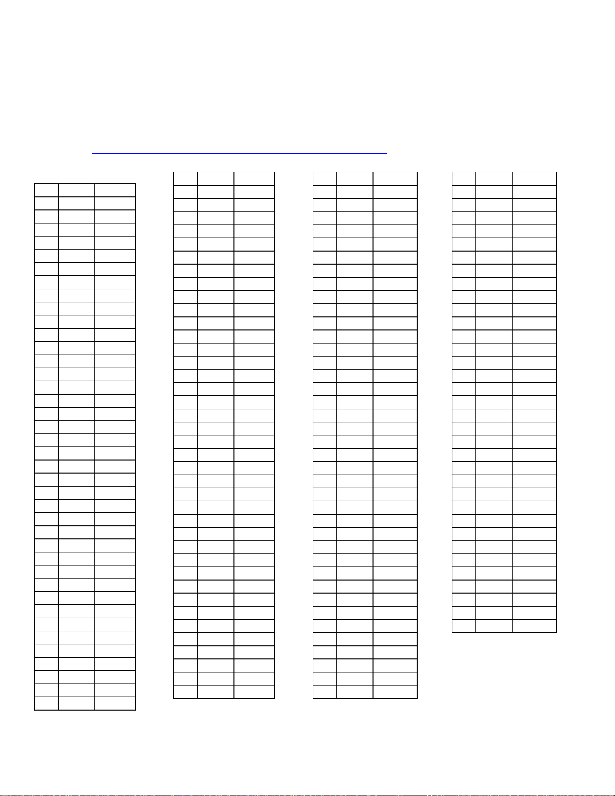
RTD Temperature
vs. Resistance Table
For European Curve, Alpha = .00385, ITS-90 1° Celsius Increments
Source: http://www.omega.com/temperature/Z/pdf/z252-254.pdf
Other manuals for 8600 Series
1
Table of contents
Other Thermo Electron Freezer manuals


