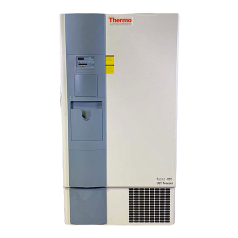
Thermo Electron Forma POWERFREEZE 840 Operating instructions

Forma®POWERFREEZE™
Ultra Low Temperature Freezer
Operating and Maintenance Manual
Manual Number 7000840 Rev. 1

FORMA
PowerFREEZE
ULT Freezer
Manual Number 7000840
1 23014 11/29/05 Changed circuit breaker (revised parts list) for 120V units aks
-- -- 6/14/05 Updated contact information aks
0 -- 9/29/04 Modified 89002416-d for Forma brand aks
Revision ECN/ECR Date Description By
Forma®POWERFREEZE™
Ultra Low Temperature Freezer
Operating and Maintenance Manual
Manual Number 7000840 Rev. 1

Thermo Electron Corporation
Packing List
(1) POWERFREEZE freezer
(1) Operating and maintenance manual 7000840
(1) Ice scraper 86000542
(1) Fuse 26387029
(1) 9 point connector adapter 86001821
(2) Door keys
(2) Anti-skid pads for leveling feet 85241913
(1) 17/19 spanner (wrench) for leveling feet 26178039
(1) Door opening limiter 51245425
(1) 8/10 spanner (wrench) for door opening limiter 26178026
(1) Back spacers 85230074
iii Forma®POWERFREEZE™Thermo Electron Corporation
Preface

Thermo Electron Corporation Forma®POWERFREEZE™ivThermo Electron Corporation
Preface
Caution Read this instruction manual. Failure to read, understand and
follow the instructions in this manual may result in damage to the unit,
injury to operating personnel, and poor equipment performance. V
Caution All internal adjustments and maintenance must be performed by
qualified service personnel. V
Important Refer to the serial tag on the back of this manual. V
Note The material in this manual is for information purposes only. The
contents and the product it describes are subject to change without notice.
Thermo Electron Corporation makes no representations or warranties with
respect to this manual. In no event shall Thermo be held liable for any
damages, direct or incidental, arising out of or related to the use of this
manual. V
Important operating and/or maintenance instructions. Read the
accompanying text carefully. V
Potential electrical hazards. Only qualified persons should perform
procedures associated with this symbol. V
Equipment being maintained or serviced must be turned off and locked
off to prevent possible injury. V
Hot surface(s) present which may cause burns to unprotected skin, or to
materials which may be damaged by elevated temperatures. V
Always use proper protective equipment (clothing, gloves, goggles, etc.) V
Always dissipate extreme cold or heat and wear protective clothing. V
Always follow good hygiene practices. V
Each individual is responsible for his or her own safety. V

Thermo Electron Corporationv Forma®POWERFREEZE™Thermo Electron Corporation
Preface
Warranty
The Warranty Period starts two weeks from the date your equipment is
shipped from our facility. This allows for shipping time so the warranty
will go into effect at approximately the same time your equipment is
delivered. The warranty protection extends to any subsequent owner
during the warranty period.
During the first two years of the warranty period, component parts proven
to be non-conforming in materials or workmanship will be repaired or
replaced at Thermo's expense, labor included. The freezer has an additional
two year warranty on the compressors, parts only, F.O.B. factory.
Installation and calibration is not covered by this warranty agreement. The
Technical Services Department must be contacted for warranty
determination and direction prior to any work being performed.
Expendable items, i.e., glass, filters, pilot lights, light bulbs and door
gaskets are excluded from this warranty.
Replacement or repair of component parts or equipment under this
warranty shall not extend the warranty to either the equipment or to the
component part beyond the original two year warranty period. The
Technical Services Department must give prior approval for the return of
any components or equipment.
THIS WARRANTY IS EXCLUSIVE AND IN LIEU OF ALL OTHER
WARRANTIES, WHETHER WRITTEN, ORAL, OR IMPLIED. NO
WARRANTIES OF MERCHANTABILITY OR FITNESS FOR A
PARTICULAR PURPOSE SHALL APPLY. Thermo shall not be liable for
any indirect or consequential damages including, without limitation,
damages relating to lost profits or loss of products.
Your local Thermo Sales Office is ready to help with comprehensive site
preparation information before your equipment arrives. Printed instruction
manuals carefully detail equipment installation, operation, and preventive
maintenance.
If equipment service is required, please call your Technical Services
Department at 1.888.213.1790 (USA and Canada) or 1.740.373.4189.
We're ready to answer your questions on equipment warranty, operation,
maintenance, service, and special applications. Outside the USA contact
your local distributor for warranty information.

Forma®POWERFREEZE™viThermo Electron Corporation
Table of Contents
Packing List . . . . . . . . . . . . . . . . . . . . . . . . . . . . . . . . . . . . . . . . . . . . .iii
Warranty . . . . . . . . . . . . . . . . . . . . . . . . . . . . . . . . . . . . . . . . . . . . . . . .v
Use and Function . . . . . . . . . . . . . . . . . . . . . . . . . . . . . . . . . . . . . . . . . . . . .1-1
General Description . . . . . . . . . . . . . . . . . . . . . . . . . . . . . . . . . . . . . .1-1
General Presentation . . . . . . . . . . . . . . . . . . . . . . . . . . . . . . . . . . . . .1-1
Freezing System . . . . . . . . . . . . . . . . . . . . . . . . . . . . . . . . . . . . . . . .1-2
Insulation . . . . . . . . . . . . . . . . . . . . . . . . . . . . . . . . . . . . . . . . . . . .1-2
Storing System . . . . . . . . . . . . . . . . . . . . . . . . . . . . . . . . . . . . . . . .1-2
Inner Chamber . . . . . . . . . . . . . . . . . . . . . . . . . . . . . . . . . . . . . . . .1-2
Outer Door . . . . . . . . . . . . . . . . . . . . . . . . . . . . . . . . . . . . . . . . . . .1-2
Casters . . . . . . . . . . . . . . . . . . . . . . . . . . . . . . . . . . . . . . . . . . . . . .1-3
Handle . . . . . . . . . . . . . . . . . . . . . . . . . . . . . . . . . . . . . . . . . . . . . .1-3
Outer Body . . . . . . . . . . . . . . . . . . . . . . . . . . . . . . . . . . . . . . . . . . .1-3
Chamber Gasket . . . . . . . . . . . . . . . . . . . . . . . . . . . . . . . . . . . . . . .1-3
Storage Systems . . . . . . . . . . . . . . . . . . . . . . . . . . . . . . . . . . . . . . . .1-4
Options and Accessories . . . . . . . . . . . . . . . . . . . . . . . . . . . . . . . . . . .1-4
Recorder . . . . . . . . . . . . . . . . . . . . . . . . . . . . . . . . . . . . . . . . . . . . .1-5
CO2Backup System . . . . . . . . . . . . . . . . . . . . . . . . . . . . . . . . . . . .1-5
Installation . . . . . . . . . . . . . . . . . . . . . . . . . . . . . . . . . . . . . . . . . . . . . . . . . .2-1
Unpacking . . . . . . . . . . . . . . . . . . . . . . . . . . . . . . . . . . . . . . . . . . . . .2-1
Installation . . . . . . . . . . . . . . . . . . . . . . . . . . . . . . . . . . . . . . . . . . . . .2-2
Back Spacer Installation . . . . . . . . . . . . . . . . . . . . . . . . . . . . . . . . . . .2-2
Door Opening Limiter . . . . . . . . . . . . . . . . . . . . . . . . . . . . . . . . . . . .2-3
Positioning the Leveling Feet . . . . . . . . . . . . . . . . . . . . . . . . . . . . . . .2-4
Optional Recorder Connection . . . . . . . . . . . . . . . . . . . . . . . . . . . . .2-4
Changing the Recorder Range . . . . . . . . . . . . . . . . . . . . . . . . . . . . .2-5
Installing Chart Paper . . . . . . . . . . . . . . . . . . . . . . . . . . . . . . . . . . .2-5
Calibrate Chart Recorder . . . . . . . . . . . . . . . . . . . . . . . . . . . . . . . .2-6
Power Connection . . . . . . . . . . . . . . . . . . . . . . . . . . . . . . . . . . . . . . .2-7
Start-Up . . . . . . . . . . . . . . . . . . . . . . . . . . . . . . . . . . . . . . . . . . . . . . .2-7
Environmental Conditions . . . . . . . . . . . . . . . . . . . . . . . . . . . . . . . . .2-8
Section 1
Section 2

vii Forma®POWERFREEZE™Thermo Electron Corporation
Specifications . . . . . . . . . . . . . . . . . . . . . . . . . . . . . . . . . . . . . . . . . . . . . . .3-1
Inner Dimensions/ Capacities . . . . . . . . . . . . . . . . . . . . . . . . . . . . . .3-2
External Dimensions . . . . . . . . . . . . . . . . . . . . . . . . . . . . . . . . . . . . .3-2
Chamber Dimensions . . . . . . . . . . . . . . . . . . . . . . . . . . . . . . . . . . . .3-2
Packaging Dimensions . . . . . . . . . . . . . . . . . . . . . . . . . . . . . . . . . . . .3-2
Operating Principles . . . . . . . . . . . . . . . . . . . . . . . . . . . . . . . . . . . . . . . . . .4-1
Instruction for Use . . . . . . . . . . . . . . . . . . . . . . . . . . . . . . . . . . . . . . . . . . . .5-1
Temperature Setpoint . . . . . . . . . . . . . . . . . . . . . . . . . . . . . . . . . . . .5-2
Fault Detection . . . . . . . . . . . . . . . . . . . . . . . . . . . . . . . . . . . . . . . . .5-3
High Temperature Setpoint . . . . . . . . . . . . . . . . . . . . . . . . . . . . . . . .5-3
Communication Devices . . . . . . . . . . . . . . . . . . . . . . . . . . . . . . . . . .5-5
Service Menu . . . . . . . . . . . . . . . . . . . . . . . . . . . . . . . . . . . . . . . . . . .5-7
Precautions . . . . . . . . . . . . . . . . . . . . . . . . . . . . . . . . . . . . . . . . . . . . . . . . . .6-1
Cleaning . . . . . . . . . . . . . . . . . . . . . . . . . . . . . . . . . . . . . . . . . . . . . . .6-1
Discarding . . . . . . . . . . . . . . . . . . . . . . . . . . . . . . . . . . . . . . . . . . . . .6-1
Cleaning the Condenser Filter . . . . . . . . . . . . . . . . . . . . . . . . . . . . . .7-1
Service and Preventive Maintenance . . . . . . . . . . . . . . . . . . . . . . . . . . .8-1
Door Seal Defrosting . . . . . . . . . . . . . . . . . . . . . . . . . . . . . . . . . . . . .8-2
Spare Parts . . . . . . . . . . . . . . . . . . . . . . . . . . . . . . . . . . . . . . . . . . . . .8-2
Fuse Replacement . . . . . . . . . . . . . . . . . . . . . . . . . . . . . . . . . . . . . . .8-2
Chamber Cleaning . . . . . . . . . . . . . . . . . . . . . . . . . . . . . . . . . . . . . . .8-2
Table of Contents
Section 3
Section 4
Section 5
Section 6
Section 7

General Presentation
Forma®POWERFREEZE™1-1Thermo Electron Corporation
Section 1 Use and Function
POWERFREEZE™ ULT Freezers are designed to freeze samples from
ambient temperature and to maintain them at a temperature as low as
-86°C. At -70°C, the metabolism of most biological samples is virtually
stopped.
These samples can be stored several months or years without altering their
properties.
The Forma POWERFREEZE freezers are designed to optimize thermal
transfer from the sample to guarantee their optimal storage conditions. The
POWERFREEZEdesign is a unique combination of a freezing system and
storage system which places a cooling coil in the top of each compartment.
FORMA
PowerFREEZE
ULT Freezer
Figure 1-1. Location of Main Components
Display
Handle
Optional
temperature
recorder
Control panel
Condenser filter access grille
Grille
Safety and
communication
devices
Electrical
connection
Power switch-
mains disconnect
General Description

Outer Door
Inner Chamber
Storing System
Insulation
Freezing System
1-2 Forma®POWERFREEZE™Thermo Electron Corporation
Section 1
Use and Function
The freezing system contains:
• Material: anodized aluminum (upper plate)
• Concept: plain upper plate, perforated bottom plate
• Cooling coils inserted in the sandwich shelf
The storing system contains:
• 4 independent compartments closed by 4 insulated inner doors
• Material: painted steel; insulation: polyurethane, thickness 0.39 inches
(10 mm)
• Magnetic closing system and “easy opening” knob
The insulation construction consists of the following material:
• Concept: 5 blocks of polyurethane 0%CFC; thickness 4.7 inches
(120 mm)
The inner chamber has the following characteristics:
• Stainless steel
• Access for CO2back-up injection
• Access for probe of 7-day recorder or extra monitoring sensor.
• Single outer door.
• Insulation thickness: 3.5 inches (90 mm)
• Insulation material: Polyurethane
• Door opening limiter located on the top left of the door. The freezer
is delivered without door opening limiter installed. After unpacking
unit, install door opening limiter to avoid damaging door hinges.

Forma®POWERFREEZE™1-3Thermo Electron Corporation
Section 1
Use and Function
• Two lip, easily changed chamber gasket
• Material: high flexibility silicone
• Material: powder coated painted steel
• Low-force single-handed operation handle
• Lock and keys (2)
• 4 rotating casters
• 2 leveling feet with anti-skid pads to prevent freezer from moving
Chamber Gasket
Outer Body
Handle
Casters

Options and
Accessories Options and accessories for the POWERFREEZE ULT freezer include
storage systems, CO2backup and seven day chart recorder.
The following table gives the dimensions, the catalog numbers and the
capacity of the freezer for each type of rack.
Table 1-1. Rack Specifications
1-4 Forma®POWERFREEZE™Thermo Electron Corporation
Section 1
Use and Function
Storage Systems
920015 Standard rack for 2" boxes, no boxes 5.3 x 10.875 x 16.5 16
820015 Standard rack for 2" boxes, with boxes 5.3 x 10.875 x 16.5 16
920018 Standard rack for 2" boxes, no boxes 5.3 x 10.875 x 22 16
820018 Standard rack for 2" boxes, with boxes 5.3 x 10.875 x 22 16
920198 Standard rack for 2" boxes, no boxes 5.3 x 10.875 x 28 16
820198 Standard rack for 2" boxes, with boxes 5.3 x 10.875 x 28 16
920009 Standard rack for 3" boxes, no boxes 5.3 x 10.875 x 16.5 16
820009 Standard rack for 3" boxes, with boxes 5.3 x 10.875 x 16.5 16
920017 Standard rack for 3" boxes, no boxes 5.3 x 10.875 x 22 16
820017 Standard rack for 3" boxes, with boxes 5.3 x 10.875 x 22 16
920197 Standard rack for 3" boxes, no boxes 5.3 x 10.875 x 28 16
820197 Standard rack for 3" boxes, with boxes 5.3 x 10.875 x 28 16
920094 Drawer-style rack for 2" boxes, no boxes 5.5 x 11.9 x 16.6 12
820094 Drawer-style rack for 2" boxes, with boxes 5.5 x 11.9 x 16.6 12
920096 Drawer-style rack for 2" boxes, no boxes 5.5 x 11.9 x 22 12
820096 Drawer-style rack for 2" boxes, with boxes 5.5 x 11.9 x 22 12
920090 Drawer-style rack for 2" boxes, no boxes 5.5 x 11.8 x 26.3 16
820090 Drawer-style rack for 2" boxes, with boxes 5.5 x 11.8 x 26.3 16
920095 Drawer-style rack for 3" boxes, no boxes 5.5 x 11.9 x 16.6 12
820095 Drawer-style rack for 3" boxes, with boxes 5.5 x 11.9 x 16.6 12
920097 Drawer-style rack for 3" boxes, no boxes 5.5 x 11.9 x 22 12
820097 Drawer-style rack for 3" boxes, with boxes 5.5 x 11.9 x 22 12
920091 Drawer-style rack for 3" boxes, no boxes 5.5 x 11.8 x 25.8 16
820091 Drawer-style rack for 3" boxes, with boxes 5.5 x 11.8 x 25.8 16
830012 Multi-drawer rack 11.2 x 11.5 x 11 1 per shelf 1 per shelf 1 per shelf
830030 Storage container 7 x 5.3 x 18.1 24 24
830032 Storage container 7 x 5.3 x 22.6 24
820030 30 position deepwell microplate rack 5.3 x 9.5 x 22 16 16
820036 36 position deepwell microplate rack 5.3 x 12 x 22 16 16
820066 66 position microplate rack 5.3 x 9.6 x 22 16 16
820002 2" cardboard box
820003 3" cardboard box
820064 64 cell divider
820081 81 cell divider
820100 100 cell divider
Dimensions (inches)
Part No. Description W x H x F-B 840/841 842/843 844/845

Forma®POWERFREEZE™1-5Thermo Electron Corporation
Section 1
Use and Function
CO2back-up (Part Number 195814 Qualified Installation 115V, 195815
Qualified Installation 208V)
The CO2back-up system is designed to maintain the sample temperature
below -60°C for several hours by injecting CO2into the freezer chamber.
The CO2back-up must be installed by qualified personnel.
7-day temperature recorder (Stock Number 201276 Qualified Installation,
201277 Factory Installed)
Available for the POWERFREEZE is a 7-day temperature recorder with
independent probe. The temperature recorder must be installed by
qualified personnel.
Replacement recorder chart paper can be purchased from Thermo
Electron. Order stock number 17020 - 6 inch, 7 day, -100°C to +38°C
circular chart paper.
Replacement pens are also available. Order stock number 245231 - Short
length red fiber tip pen and 245232 - Medium length blue fiber tip pen.
CO2Backup System
Recorder


Forma®POWERFREEZE™2-1Thermo Electron Corporation
Section 2 Installation
Due to the weight of the freezer, all lifting and transporting must be done
by trained personnel using proper handling equipment that complies with
current regulations.
The freezer must be supported from underneath. If it has to be transported
without its pallet, for example on a staircase, professional handling is
required.
1. Remove the straps and the cling film. Remove the plank located on the
top of the freezer. Unscrew the nuts and remove the side bar by tilting
the machine slightly.
2. Place the plank sideways in contact with the pallet and in line with the
wheels of the machine. Remove the freezer from the pallet by rolling it
down the plank.
Note Two people are needed for this operation. V
Figure 2-1. Unpacking
Unpacking
Plank
Straps
Nuts
Side bar
Pallet
Plank

Back Spacer
Installation
2-2 Forma®POWERFREEZE™Thermo Electron Corporation
Section 2
Installation
Install the back spacers as shown below to allow proper air circulation at
the back of the freezer when positioned against a wall.
Figure 2-2. Back Spacers Installed
1. Never transport the freezer on its side.
2. Check that no accessories or printed material are left in the packaging.
3. Install the freezer in a suitable environment :
a. To ensure proper ventilation of the refrigeration system and
guarantee correct functioning of the freezer, it is extremely
important not to place any object within 8 inches of the front,
back or side ventilation grilles (see Back Spacer Installation).
b. The room should be well ventilated and include mechanical air
exhaust if the optional CO2back-up is in use. The environment
must be non-corrosive and the floor must be level.
4. Check that the mains voltage corresponds to the freezer’s voltage.
5. After locating the instrument, install non-skid pads.
Installation

Door Opening Limiter To install the door opening limiter:
1. Align the holes of two plastic washers and two spacers with those on
the body of the freezer and the door.
2. Position the limiter as shown in Figure 2-3 and secure in place with the
two bolts and washers, using the box spanner (wrench).
3. Check that the limiter slides easily.
Figure 2-3. Door Opening Limiter
Forma®POWERFREEZE™2-3Thermo Electron Corporation
Section 2
Installation
Bolt
Plastic
washer
Washer
Spacer
Limiter
Door
Body

2-4 Forma®POWERFREEZE™Thermo Electron Corporation
Section 2
Installation
If the freezer has an optional 7-day recorder, a power cable must be
connected before use. To connect power to the recorder:
1. Disconnect power to the freezer.
2. Open the condenser filter access grille located at the lower front of the
freezer (see Figure 1-1).
3. Locate the cable extending from the recorder and connect to the cable
secured to the bottom of the compressor compartment (mate-n-lock
connection).
4. Replace the front grille.
Optional Recorder
Connection
There are two leveling feet located at the front of the freezer.
1. Unscrew the leveling feet.
2. Place an anti-skid pad beneath each one (2 anti-skid pads are
provided).
3. Using the 19 mm spanner provided with the freezer, continue to
unscrew the leveling feet until the front of the freezer is lifted about
one millimeter.
4. Check the stability of the freezer by opening the door, then watching it
close. Adjust the height of the feet accordingly.
Positioning the
Leveling Feet
Figure 2-4. Leveling Feet

Installing Chart Paper 1. Open the glass door of the recorder and press button #3 until the pen
begins to move outward.
2. Unscrew the knob at the center of the chart and remove the paper.
3. Install the new chart paper, position the paper to the correct time line
and replace the knob.
4. Remove the cap from the felt pen and press button #3.
The chart recorder contains eight temperature ranges and is factory-
programmed for the freezer.
1. Press and hold button #3 for one second, then let the pen move off the
chart paper.
2. Press and hold for five seconds either button #1 or button #2.
3. Release the button and the green LED will begin to flash. Count the
number of flashes to determine the present program setting.
4. To change the program setting, press the left or right arrows to increase
or decrease the count.
5. When the desired program number is flashing, press button #3 to
bring the pen arm back onto the chart. Recording will begin in the
new program.
Table 2-1. Chart Recorder Program Ranges
Forma®POWERFREEZE™2-5Thermo Electron Corporation
Section 2
Installation
Changing the Recorder
Range
Program From To
1-40 30°C
2 0 60°C
3-100 38°C
4-5 50°C
5 0 100°C
6-100 200°C
7-115 50°C
8-10 70°C

The recorder must be in service for 24 hours before performing the
following calibration procedure.
1. Place an accurate thermometer in the chamber next to the recorder
probe.
2. Temperature probes for the recorder are located in the left front corner
of the freezer chamber (Figure 2-6).
Figure 2-6. Recorder Probe Placement
3. After about three minutes, compare the thermometer reading with the
chart recorder reading.
4. If an adjustment is necessary, press the #1 button to move the pen to
the left or the #2 to move the pen to the right. The button must be
held about five seconds before the pen begins to move. Release the
button when the pen position matches the thermometer.
Note The felt-tip pen on the recorder requires periodic replacement.
Usually the ink will appear to fade before replacement becomes necessary.
Additional pen tips may be purchased. V
2-6 Forma®POWERFREEZE™Thermo Electron Corporation
Section 2
Installation
Calibrate Chart Recorder
Freezer probe Recorder probe
Chamber tube

Start-Up
Power Connection See the serial tag on the side of the unit for electrical specifications. The
freezer should be operated on a dedicated grounded service. Check the
voltage rating on the serial tag of the unit and compare it with the outlet
voltage.
Warning For personal safety, this apparatus must be properly grounded. V
The power cord provided on this unit is equipped with a three-prong plug
which mates with a standard three prong grounding wall receptacle to
minimize the possibility of electric shock hazard. The wall receptacle and
circuit should be checked by a qualified electrician to ensure that the
receptacle can provide adequate current and is properly grounded.
Where a standard two-prong wall receptacle is encountered, it is the
personal responsibility and obligation of the user to have it replaced with a
properly grounded three-prong wall receptacle. Do not under any
circumstances cut or remove the third (ground) prong from the power
cord. Do not use a two-prong adapter plug.
Note Colors of wires in mains cable: black 1 = Line , white 2 = Neutral,
Earth/Ground = yellow; green. V
Before turning on the freezer, install the fuse located at the back of the
freezer.
Turn on the freezer by activating the power switch located in the back of
the unit. On start-up of the freezer, the display shows the chamber
temperature and the visual and audible alarms are activated. During
temperature stabilization, the audible alarm may be temporarily silenced
by pressing the mute key.
During the cooling procedure, the freezer displays the chamber
temperature.
It takes about 6 hours to cool down the freezer from +20°C to -80°C.
Forma®POWERFREEZE™2-7Thermo Electron Corporation
Section 2
Installation
This manual suits for next models
5
Table of contents
Other Thermo Electron Freezer manuals
Popular Freezer manuals by other brands
Matsui
Matsui MUF48W13E instruction manual
Frigidaire
Frigidaire GLFC1526FW - 14.8 cu.ft. Manual Defrost Chest... Features & dimensions
AEG
AEG SANTO 70322 KG operating instructions

Campingaz
Campingaz Smart Cooler Electric 20 l Instruction leaflet

Veripart
Veripart VRIEZER VPVR144NFE user manual

Bosch
Bosch GIN81H Series INFORMATION FOR USE

