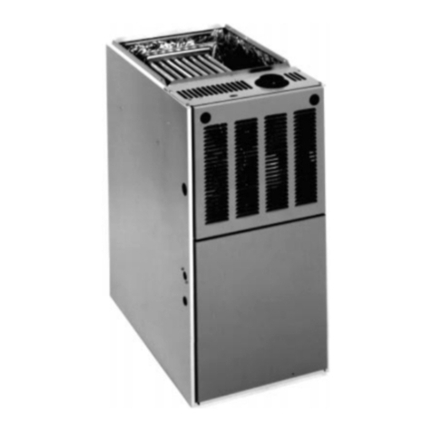
Thermo Products Spirit Series Setup guide


This manual suits for next models
4
Table of contents
Other Thermo Products Furnace manuals

Thermo Products
Thermo Products Spirit VHF-ABE Setup guide

Thermo Products
Thermo Products VH-BBP Spirit Series Instruction manual
Thermo Products
Thermo Products Thermo Pride OH6FA072D48B User manual
Thermo Products
Thermo Products THV1M119A960SA User manual
Thermo Products
Thermo Products VH8FA119P60B User manual
Popular Furnace manuals by other brands
Nortek
Nortek KG7TL installation instructions
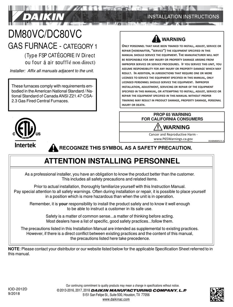
Daikin
Daikin DM80VC installation instructions
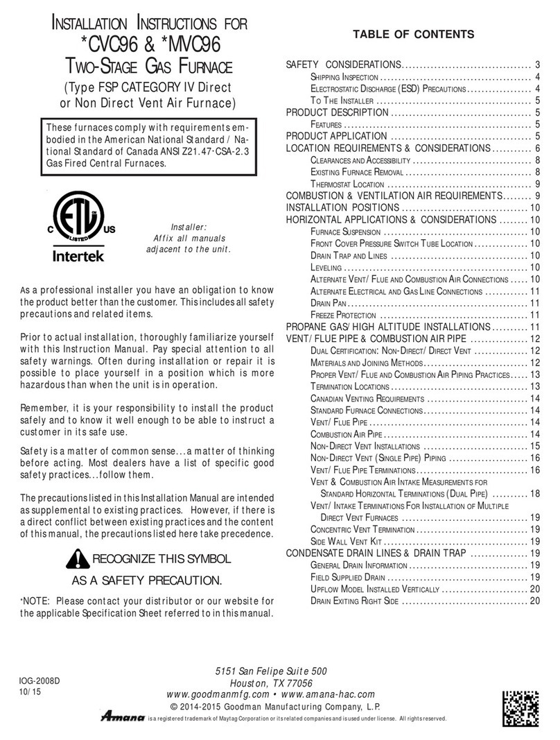
Maytag
Maytag Amana CVC96 Series installation instructions
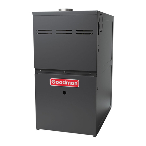
Goodman
Goodman GMEC80 Service instructions
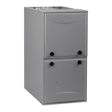
ICP
ICP A Series installation instructions
Bryant
Bryant 312A Installation, start-up, operating and service and maintenance instructions
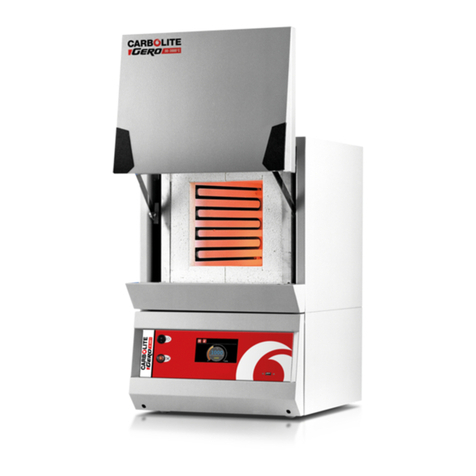
Carbolite
Carbolite CWF Installation, operation & maintenance instructions
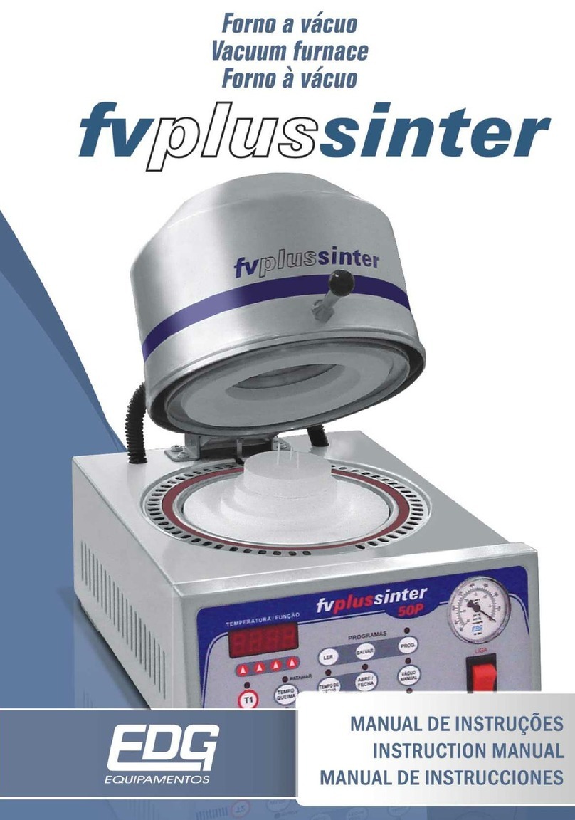
EDG
EDG Fv Plus Sinter instruction manual

Carbolite Gero
Carbolite Gero HTRH operating instructions

Thermo Scientific
Thermo Scientific BF51634BC-1 Installation and operation manual
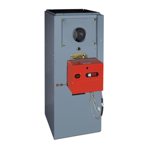
Carrier
Carrier OBMAAB installation instructions
Rheem
Rheem RGPK Series User's information manual

Lennox
Lennox EL180UHNE Series User's information manual

VERDER
VERDER Carbolite TZF Series Installation, operation & maintenance instructions
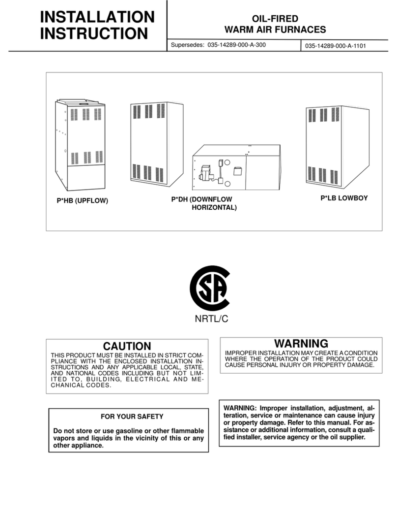
Coleman
Coleman P*HBX12F08001 installation instructions

Carbolite Gero
Carbolite Gero ELF 11/14B Installation, operation and maintenance instructions
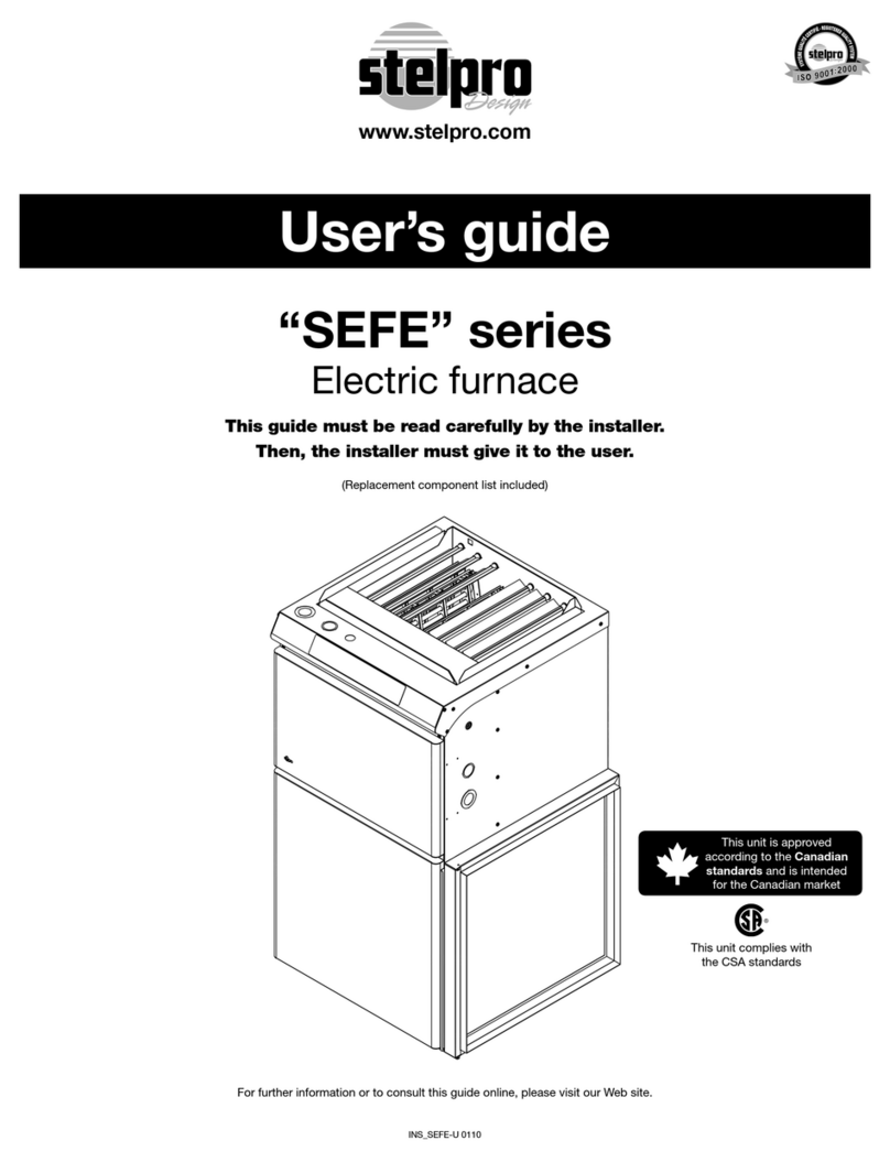
Stelpro
Stelpro SEFE Series user guide

Bryant
Bryant CONDENSING GAS FURNACE 352MAV Installation, start-up, and operating instructions