IMPORTANTINSTRUCTIONS
When using electrical appliances, basic precautions should
always be followed to reduce the risk of fire, electric shock,
and injury to persons, including the following:
1.Read all instructions before installing or using this heater. 2.This
heater is hot when in use. To avoid burns, do not let bare skin touch
hot surfaces. Keep combustible materials, such as furniture, pillows,
bedding, papers, clothes, and curtains at least
3 feet (0.9m) from
the front of the heater and keep them away
from the sides
and rear.
3.
Extreme caution is necessary when any heater is used by or
near children or invalids and whenever the heater is left
operatingandunattended.
4.
Alwaysunplugheaterwhennotinuse.
5.
Do not operate any heater after it malfunctions. Disconnect
9.To disconnect the heater, turn the controls to the off position and
shut
off the heater circuit power at the main disconnect panel. 10.Do
not insert or allow foreign objects to enter any ventilation
or exhaust opening as this may cause an electric shock or
fire, or damage the heater.
11.
To prevent a possible fire, do not block air intakes or exhaust
in any manner. Do not use on soft surfaces, like a bed, where
openingsmaybecomeblocked.
12.
Use this heater only as described in this manual. Any other use
not recommended by the manufacturer may cause fire ,electric
shock,orinjurytopersons.
13.
A heater has hot and arcing or sparking parts inside. Do not
useitinareas where gasoline, paint,orflammablevaporsor
liquidsareusedorstored.
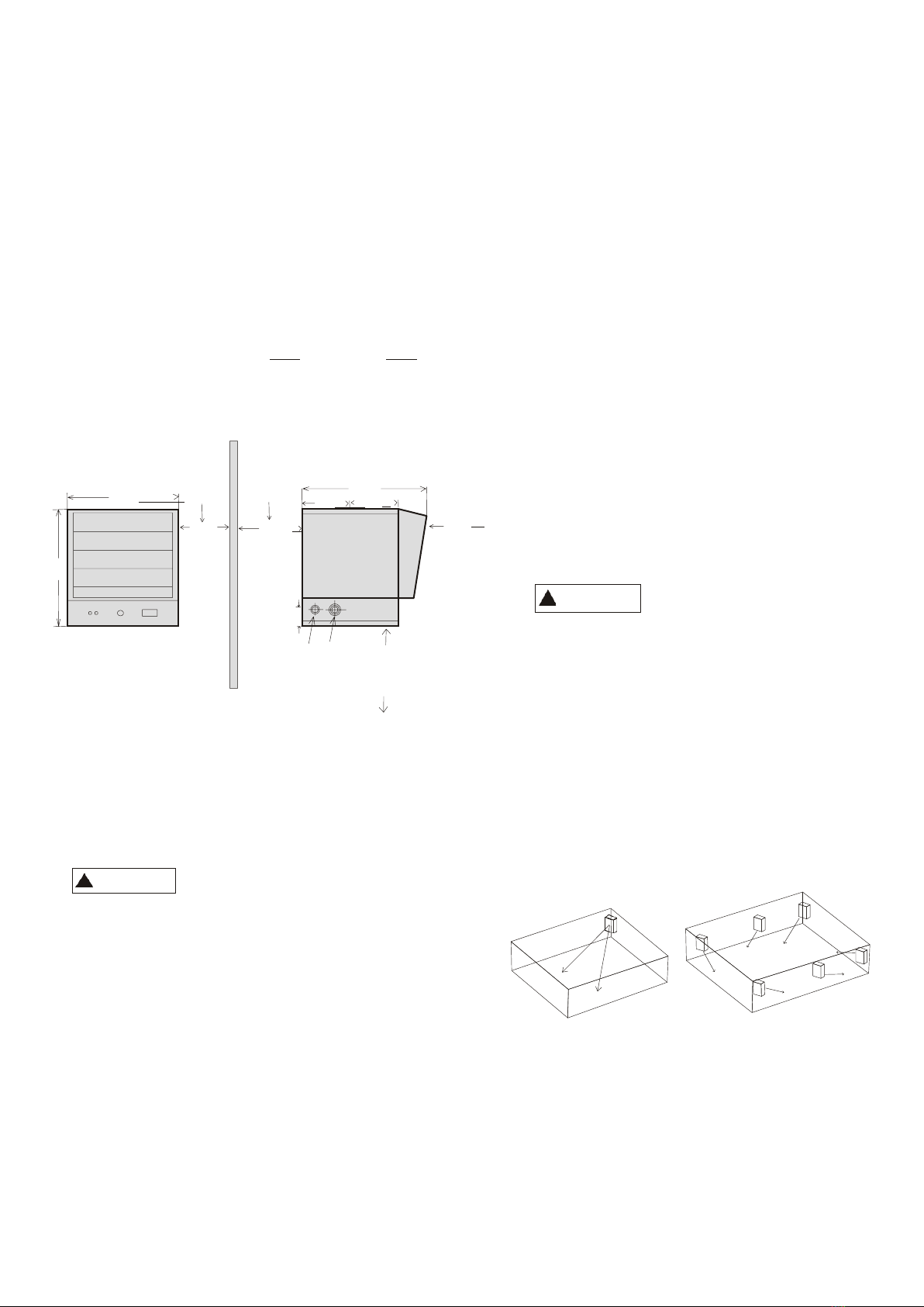
14.
Donot install closerthan 24 inchestofurniture, andother objects.
Do not install closer than 13 inches to side wall. Do not install
power at service panel and have heater inspected by a reputable
closer than
7
3
/
8
inches to back wall
.
electrician before reusing.
6.Do not use outdoors.
7.
Thisheaterisnotintendedforuseinbathrooms
,
laundry
areas and similar indoor locations
.
Never locate heater where
itmayfallintoabathtuborother water container.
8.
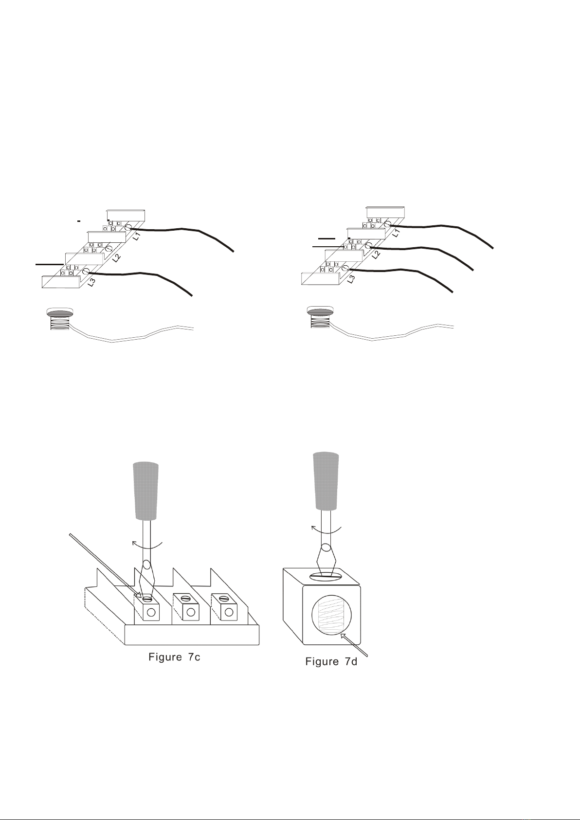
For supply connections
,
use wire suitable for at least
75 C. See wiring diagram for wire size.
1
5
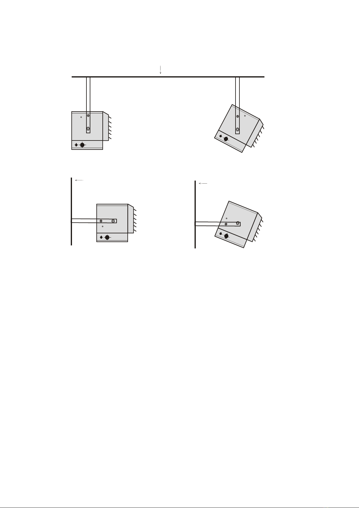
.
Mount with bottom of heater at least 2
.
4m above floor or grade
.
1
6
.
Use copper wire only
.
17.
Thisheatercomes with a red visual alarmtowarnthat
parts of the heater are getting excessively hot.If the alarm
illuminates, immediately turn the heater off and inspect for any
objectsonoradjacenttotheairfloworother wise causehigh
temperatures to have occurred. DO NOT OPERATE THE
HEATER WITH THE ALARMILLUMINATING.
SAVE THESE INSTRUCTIONS