THERMOBILE ITA 35 R User manual
ITA35 R
SATI/ATI1102-70.ver-500.020.042
/i
-2--1-
- 3 -
- 4 - - 5 -
000.000.00edoc .dorP
00 Kw
00000 Kcal
3
000000 BTU
0000 m /hr
000V/0,0 Amp.
Capacity
Airflow
El.con .................................................
.................................................
.................................................
.................................................
.............................................
..........................................
Fabr.year 0000 Serial nr: 00.0000
Made by THERMOBILE Ind. B.V. Breda, Holland
FD ECBA
A
B
C
Max. 45
1000 mm
O
A
B
2ITA 35 R 3
40.019.005 rev 00 - 2013
ITA 45/75 ROBUST
41.350.095 rev 01 - 2021
31102-70.ver-500.020.04SATI/ATI
/i
/i
- 6 -
8mm
4.5 mm
C
A
B
ITA 35
12345678
D
Nr. ITA 35 R
A 4 mm
3-2
B
C 2 mm
D0 mm
2 40.019.005 rev 00 - 2013 ITA 45/75 ROBUST 3
41.350.095 rev 01 - 2021
ITA 35 R
4 40.020.005 - rev. 07 - 2011 ITA/ITAS
- 7 -
AB C E
FGH
D
4ITA 35 R 5
40.019.005 rev 00 - 2013
ITA 45/75 ROBUST
41.350.095 rev 00 - 2017

ITA/ITAS 40.020.005 - rev. 07 - 2011 5
Nederlands....................................6
English ........................................15
Deutsch .......................................23
Français ......................................33
Español .......................................42
Русский язык.............................51
4 40.019.005 rev 00 - 2013 ITA 45/75 ROBUST 5
41.350.095 rev 01 - 2021
ITA 35 R

6 40.020.005 - rev. 07 - 2011 ITA/ITAS
Nederlands
Nederlands
Inhoud
Veiligheidsinstructies ...................................7
Inleiding .......................................................7
Voorbereidingen...........................................8
Bediening.....................................................9
Onderhoud...................................................9
Storingzoeken............................................ 11
Reserveonderdelen ...................................13
Technische informatie................................13
Installatie van accessoires.........................14
EG-Verklaring van overeenstemming ........14
Voorwoord
Deze handleiding bevat de
gebruiksaanwijzing voor de op de kaft
vermelde heteluchtkachels. De informatie in
deze handleiding is belangrijk voor een juist
en veilig gebruik van de heteluchtkachel.
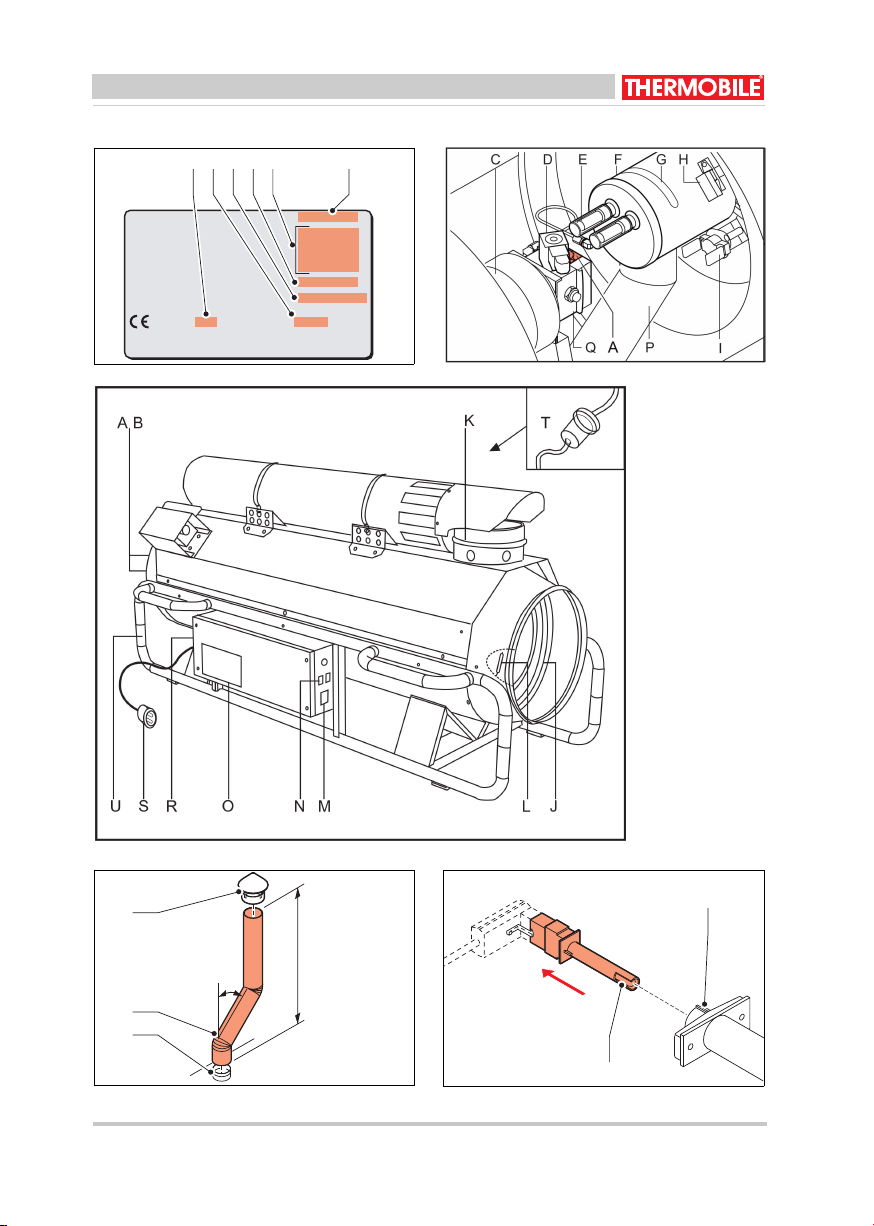
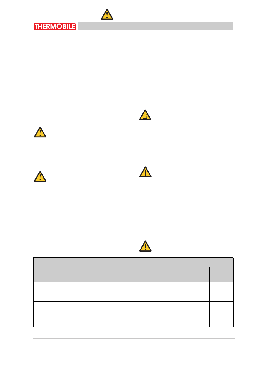
Productidentificatie (fig. 1)
Het identificatieplaatje is bevestigd op de
zijkant van de heteluchtkachel. Het
identificatieplaatje bevat de volgende
gegevens:
A Productiejaar
B Serienummer
C Elektrische aansluiting
D Luchtverplaatsing
E Vermogen
F Productiecode
Service en technische ondersteuning
Neem voor informatie over de
heteluchtkachel contact op met uw dealer of
de fabrikant. Zorg dat u de volgende
gegevens bij de hand hebt: type en
serienummer van de heteluchtkachel.
Garantie en aansprakelijkheid
Voor garantie en aansprakelijkheid, zie de
algemene garantiebepalingen.
Milieu
Let op
De kachel is gemaakt van diverse
metalen en kunststoffen. De kachel
bevat tevens elektronische
onderdelen, die als elektronisch afval
moeten worden behandeld. Neem
contact op met uw dealer voor
nadere informatie.
All
een van
t
oepass
i
ng
i
n
d
e
Europese Unie
Afvalverwijdering van elektrische
& elektronische apparatuur voor
zakelijk gebruik.
Voor nadere informatie aangaande
het wegwerpen van producten voor
zakelijke doeleinden aan het einde
van hun levensduur, wordt u verzocht
contact op te nemen met uw dealer
of distributeur in uw land. Dit product
mag niet samen met of in de vorm
van commercieel afval worden
weggegooid.
640.019.005 rev 01 - 2021 ITA 35 R 7
40.019.005 rev 00 - 2013
ITA 45/75 ROBUST

ITA/ITAS 40.020.005 - rev. 07 - 2011 7
Nederlands
1 VEILIGHEIDSINSTRUCTIES
1.1 Pictogrammen in deze handleiding
1.2 Pictogrammen op de
heteluchtkachel (fig. 2)
A Pompdruk
1.3 Gebruik dit product waarvoor het
bestemd is
De heteluchtkachel is ontworpen voor
verwarming van bouwplaatsen,
werkplaatsen, opslagloodsen, magazijnen,
kassen, (kippen)stallen, polytunnels en voor
het drogen van gebouwen,
landbouwproducten en bollen.
1.4 Algemene instructies
2 INLEIDING
2.1 Doel
Deze heteluchtkachels zijn indirect gestookte
kachels met fotocelbeveiliging en met
aansluitingen voor een ruimtethermostaat en
schoorsteen.
De heteluchtkachels zijn getest op zeeniveau
bij een temperatuur van 20 °C.
2.2 Werkingsprincipe
Een elektromotor drijft een ventilator en een
brandstofpomp aan. De pomp zuigt brandstof
uit de tank naar een magneetklep.
De ventilator blaast lucht in en rond de
branderkamer.
De magneetklep opent 12 seconden na
inschakeling van de heteluchtkachel en de
brandstof komt onder hoge druk in de
verstuiver.
VOORZICHTIG
Wijst op gevaar voor beschadiging
van de apparatuur.
WAARSCHUWING
Wijst op een gevaarlijke situatie, die
de dood of ernstige verwondingen tot
gevolg kan hebben.
WAARSCHUWING
Schakel bij onderhouds- of
reparatiewerkzaamheden aan de
heteluchtkachel altijd de elektrische
stroom uit!
Heet
Sommige vlakken kunnen heet zijn!
Wacht met onderhoud totdat deze
onderdelen voldoende zijn afgekoeld.
Suggesties en tips om de uitvoering
van de betreffende taken of
handelingen te vereenvoudigen.
WAARSCHUWING
• Lees deze handleiding
zorgvuldig door, alvorens de
heteluchtkachel te gebruiken.
• Bewaar dit document bij de
heteluchtkachel.
• Volg de beschreven procedures.
• Leun nooit op de
heteluchtkachel.
• Houd minimaal 2 meter afstand
van de uitblaasopening van de
heteluchtkachel.
• Zorg dat er voldoende lucht is
voor een goede verbranding.
• Zorg dat er geen licht
ontvlambaar materiaal in de
buurt van de heteluchtkachel
komt.
• Voer uitsluitend reparatie- en
onderhoudswerkzaamheden uit
als de heteluchtkachel voldoende
is afgekoeld, en nadat de steker
uit de contactdoos is verwijderd.
6 40.019.005 rev 00 - 2013 ITA 45/75 ROBUST 7
41.350.095 rev 01 - 2021
ITA 35 R

SATI/ATI1102-70.ver-500.020.048
Nederlands
De verstoven brandstof wordt ontstoken door
een vonk tussen de elektroden. Het licht van
de vlam activeert een fotocel. Na het
verstrijken van de veiligheidsperiode, wordt
de ontsteking uitgeschakeld.
De magneetklep sluit als de heteluchtkachel
wordt uitgeschakeld, of als de vlam stopt ten
gevolge van een storing.
De ventilator blijft draaien totdat hij door een
thermostaat wordt uitgeschakeld: de
koelcyclus is voltooid.
2.3 Hoofdonderdelen (fig. 2 en 3)
A Rooster
B Ventilator
C Elektromotor
D Magneetklep
E Elektrode (2x)
F Branderkop
G Luchtschuif
H Fotocel
I Nakoelthermostaat
J Branderkamer/warmtewisselaar
K Uitlaatpijp
L Maximaalthermostaat
M Aan-/Uitschakelaar I-0-II
N Resetschakelaar
O Identificatieplaat
P Luchtinlaat brander
Q Brandstofpomp
R Aansluiting voor ruimtethermostaat
S Kabel met steker
T Brandstoffilter
U Duwbeugel
2.4 Accessoires
• Schoorsteen met regenkap
• Thermostaat voor ruimte temperatuur
• Enkelvoudige uitlaat met leiding
• Meervoudige uitlaat met leiding
3 VOORBEREIDINGEN
3.1 Verpakking verwijderen
1. Verwijder de verpakking van de
heteluchtkachel.
3.2 Installatie
1. Zorg ervoor dat de heteluchtkachel
horizontaal staat.
2. Vul de tank met brandstof.
3. Zorg dat er voldoende afstand is tussen
de muur en de luchtinlaat. De afstand
moet minimaal 1 m. zijn.
4. Zorg ervoor dat de verwarmde lucht
ongehinderd kan doorstromen. De
afstand tussen de uitlaat en een
eventueel obstakel moet minimaal 2 m.
zijn.
5. Controleer het ventilatie-oppervlak: per
kW is een oppervlak van 25 cm2 nodig.
6. Controleer de aansluiting van de
ruimtethermostaat.
Verwijder het dopje niet, als u geen
ruimtethermostaat gebruikt.
VOORZICHTIG
Gebruik uitsluitend dieselolie of
petroleum.
VOORZICHTIG
• Wees voorzichtig bij het vullen
van de tank. Verwijder eventuele
gemorste olie van de
heteluchtkachel en van de vloer.
• Dieselolie heeft de neiging dikker
te worden bij lage temperaturen.
Hierdoor kunnen de filters
verstopt raken. Voeg maximaal
15% petroleum aan de brandstof
toe bij temperaturen lager dan
-5 °C, of zorg dat de brandstof
vorstvrij is, of gebruik de
(optionele) tankverwarming.
840.019.005 rev 01 - 2021 ITA 35 R 9
40.019.005 rev 00 - 2013
ITA 45/75 ROBUST
ITA/ITAS 40.020.005 - rev. 07 - 2011 9
Nederlands
Verwijder het dopje om een
ruimtethermostaat aan te sluiten.
7. Installeer de schoorsteen (1 m en een
regenkap).
8. Zorg dat de I-0-II schakelaar op 0 staat.
9. Controleer de voedingsspanning: zie het
identificatieplaatje.
10. Steek de steker in de contactdoos.
11. Druk de resetschakelaar in.
3.3 Opstarten verwarmen
1. Zet de schakelaar op stand II om de
verwarming in te schakelen.
2. Stel de ruimtethermostaat in.
De heteluchtkachel levert warme lucht na
ongeveer 10 seconden.
4
4.2
1. Schakel de heteluchtkachel uit.
De magneetklep gaat dicht en sluit de
brandstoftoevoer af.
2. Schakel de elektrische stroom uit.
5 ONDERHOUD
5.1 Onderhoudstabel
Registreer na elk winterseizoen het
onderhoud in de tabel achterin dit boek.
VOORZICHTIG
Schakel de heteluchtkachel niet in
als de tank leeg is!
VOORZICHTIG
Het brandstofsysteem ontlucht via de
verstuiver. Het apparaat kan een
aantal keren afslaan, als het wordt
gestart met een leeg filter. Om dit te
herstellen: druk de resetschakelaar
in.
VOORZICHTIG
Na het uitschakelen van de
heteluchtkachel, blijft de ventilator
nog draaien. De ventilator koelt de
heteluchtkachel om schade door
oververhitting te voorkomen.
De ventilator stopt automatisch.
Verwijder de steker pas uit de
contactdoos als de ventilator niet
meer draait!
VOORZICHTIG
Schakel de stroomtoevoer niet uit bij
gebruik van tankverwarming.
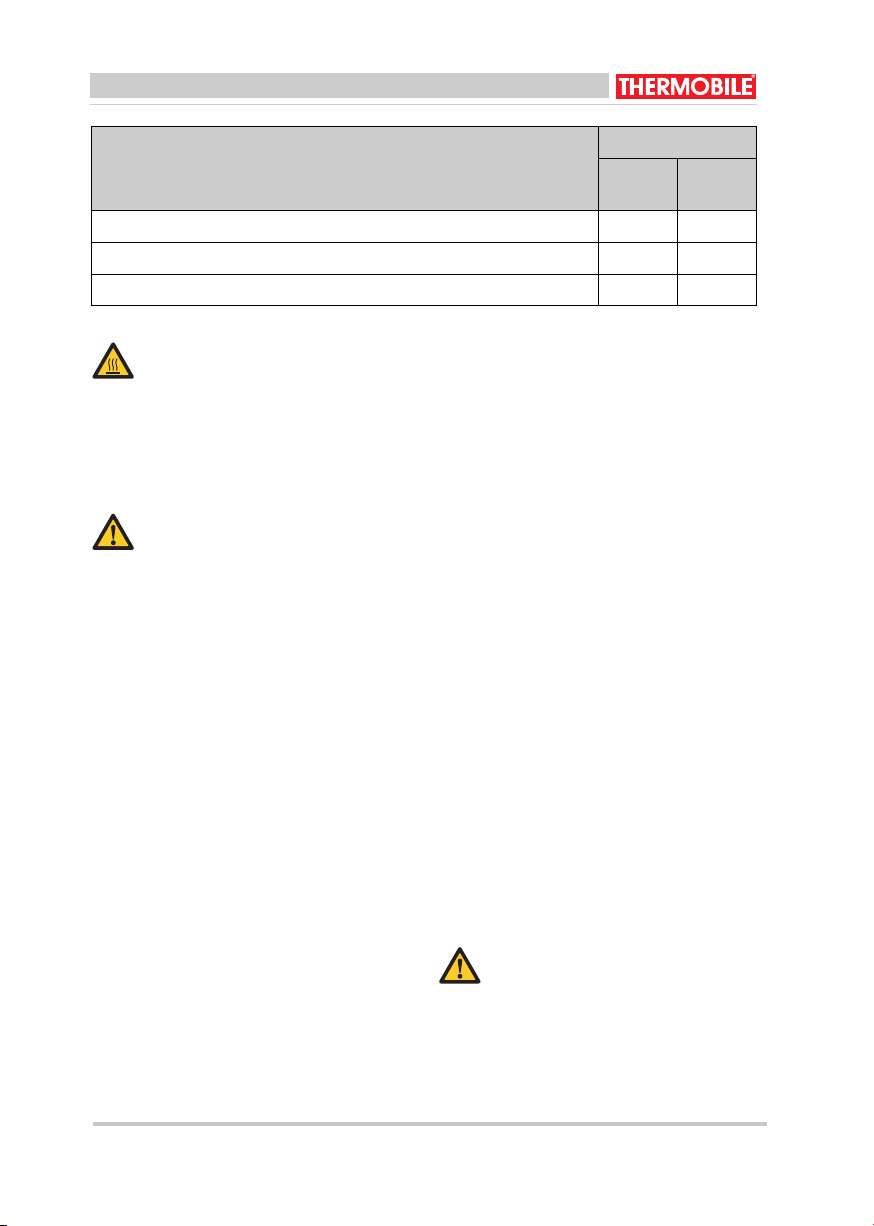
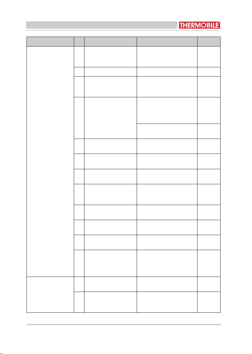
Beschrijving Periode
Jaarlijks Elke
2 jaar
Leeg de tank en spoel deze met petroleum. X
Reinig het filter in de vuldop van de tank. X
Controleer de fotocel op beschadiging. Zorg dat de fotocel vrij is van
stof en aanslag.
X
Controleer de afstelling van de elektroden. X
8 40.019.005 rev 00 - 2013 ITA 45/75 ROBUST 9
41.350.095 rev 01 - 2021
3.3.1 Opstarten alleen ventileren
Zet de schakelaar op stand I om de
ventilatiestand in te schakelen.
WAARSCHUWING
Op STAND I moet altijd en met diesel
gevulde tank aangesloten zijn. Schade door
drooglopen van de pomp valt niet onder de
garantie!
4.1
Heet
Raak de schoorsteen en
uitblaasopening niet aan!
De schoorsteen en uitblaasopening
worden heet tijdens bedrijf!
Uitschakelen
Bediening
Tijdens bedrijf
ITA 35 R
10 40.020.005 - rev. 07 - 2011 ITA/ITAS
Nederlands
5.2 Algemeen
Als de heteluchtkachel lange tijd niet wordt
gebruikt:
1. Tap de tank af en spoel deze met
petroleum.
2. Vul de tank met dieselolie om roest te
voorkomen.
3. Laat de heteluchtkachel 3 minuten
branden. Dit beschermt de pomp tegen
roest.
4. Zorg dat de branderkop vrij is van stof en
aanslag.
Een vuile branderkop veroorzaakt een
slechte verbranding, waardoor roet en
koolmonoxide worden aangemaakt en de
branderkamer wordt beschadigd.
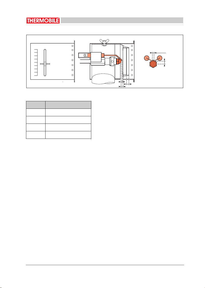
5.3 Afstelling luchtinlaat en
elektroden (fig. 6)
A Afstand verstuiver-stuwplaat
B Opening luchtinlaat
C Afstand verstuiver-elektrode
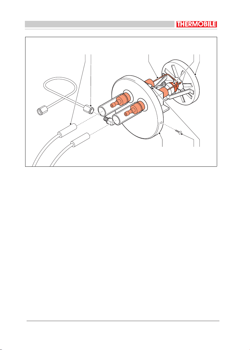
5.4 Elektroden (fig. 7)
Elektroden controleren:
1. Verwijder het deksel van de
heteluchtkachel.
2. Verwijder de olieleiding (B).
3. Maak de kabels van de elektroden (A)
los.
4. Verwijder de schroeven (G).
5. Verwijder de branderkop (F).
6. Reinig de elektroden (C) en stel ze
opnieuw af.
De elektroden moeten vrij zijn van vuil,
vet, brandstof, enz.
Als de punten van de elektroden te veel
verbrand zijn en afstelling niet mogelijk
is: vervang de elektroden.
7. Draai schroef (F) los.
8. Stel de elektroden opnieuw af.
Monteer de branderkop weer in omgekeerde
volgorde.
Elektroden vervangen:
1. Voer stap 1 tot en met 7 van "elektroden
controleren" uit.
2. Vervang de elektroden.
3. Stel de elektroden af.
Monteer de branderkop weer in omgekeerde
volgorde.
5.5 Verstuiver (fig. 7)
Verstuiver controleren:
1. Verwijder het deksel van de
heteluchtkachel.
Vervang het brandstoffilter. X
Controleer de verstuiver. X
Reinig de warmtewisselaar. X
Beschrijving Periode
Jaarlijks Elke
2 jaar
Heet
Raak de schoorsteen en
uitblaasopening niet aan!
Wacht met onderhoud totdat de
schoorsteen en de uitblaasopening
zijn afgekoeld.
WAARSCHUWING
Schakel de elektrische stroom uit
tijdens onderhoud.
WAARSCHUWING
Raak het filter van de verstuiver niet
aan. Hierdoor kan de verstuiver
beschadigd raken.
10 ITA 35 R 11
40.019.005 rev 00 - 2013
ITA 45/75 ROBUST
41.350.095 rev 01 - 2021

ITA/ITAS 40.020.005 - rev. 07 - 2011 11
Nederlands
2. Verwijder de olieleiding (B).
3. Maak de kabels van de elektroden (A)
los.
4. Verwijder de schroeven (G).
5. Verwijder de branderkop (H).
6. Controleer de verstuiver (D).
Als de verstuiver zwart is door roet of
cokes: de verstuiver vervangen.
Monteer de branderkop weer in omgekeerde
volgorde.
Verstuiver vervangen:
1. Voer stap 1 tot en met 6 van "verstuiver
controleren" uit.
2. Verwijder de elektroden (C).
3. Verwijder de stuwplaat (E).
4. Verwijder de verstuiver (D).
5. Vervang de verstuiver: gebruik het juiste
type!
6. Monteer de stuwplaat.
7. Stel de elektroden opnieuw af, zie fig. 6.
Monteer de branderkop weer in omgekeerde
volgorde.
5.6 Fotocel (fig. 5)
Fotocel controleren:
1. Verwijder het deksel van de
heteluchtkachel.
2. Verwijder de fotocel uit de houder (A).
3. Reinig de fotocel als het glas zwart is (B).
Als het glas barsten vertoont, moet de
fotocel worden vervangen door de
dealer.
Monteer de fotocel weer in omgekeerde
volgorde.
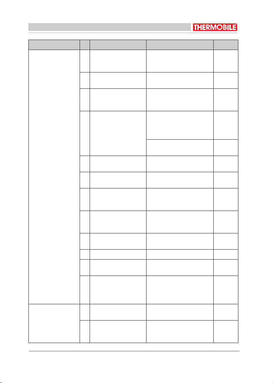
6 STORINGZOEKEN
6.1 Tabel storingzoeken
/i
Zorg dat de stroom is ingeschakeld
en de brandstoftank vol is, voordat u
begint met storingzoeken.
WAARSCHUWING
Neem altijd de netaansluiting los
tijdens reparaties!
Storing Oorzaak Oplossing Actie
De heteluchtkachel
start niet.
1 Er zit geen afdekkapje
op de
thermostaataansluiting.
Breng het kapje aan. Gebruiker
2 De thermostaat is niet
goed ingesteld.
Corrigeer de instelling. Gebruiker
3 Er is een storing in de
branderautomaat.
Vervang de branderauto-
maat.
Dealer
4 De ventilator draait
onregelmatig of is
geblokkeerd.
Controleer de brandstof-
pomp.
Controleer de motor.
Gebruiker
5 De brandstofpomp zit
vast.
Vervang de brandstofpomp. Dealer
10 40.019.005 rev 00 - 2013 ITA 45/75 ROBUST 11
41.350.095 rev 01 - 2021
ITA 35 R
12 40.020.005 - rev. 07 - 2011 ITA/ITAS
Nederlands
De heteluchtkachel
stopt met branden.
De resetknop licht op.
6 Er is lucht in het brand-
stofsysteem tijdens het
starten.
Druk de resetknop in. Her-
haal indien nodig de startpro-
cedure.
Gebruiker
7 Het brandstoffilter is ver-
stopt.
Reinig het filter of vervang
het.
Gebruiker
8 De luchtschuif van de
brander is verkeerd
afgesteld.
Stel de luchtschuif af, zie
fig. 6.
Dealer
9 De magneetklep opent
niet.
Controleer de elektrische
aansluiting. Als de schake-
laar op “O” en “I” wordt gezet,
moet een “klik” te horen zijn.
Gebruiker
Reinig of vervang de mag-
neetklep.
Dealer
10 De pompdruk is ver-
keerd ingesteld.
Stel de pompdruk met behulp
van een manometer in.
Dealer
11 De pompkoppeling is
defect.
Vervang de pompkoppeling. Dealer
12 Er is een luchtlek in de
aanzuigleiding of in het
hoofdfilter.
Controleer en vervang zono-
dig.
Gebruiker
13 Het beschermgaas voor
de luchtinlaat is vuil of
verstopt.
Maak het beschermgaas
schoon.
Gebruiker
14 Er is onvoldoende aan-
voer van frisse lucht.
Zet een deur of raam open. Gebruiker
15 De fotocel is vuil. Reinig de fotocel, zie fig. 5. Gebruiker
16 De warmtewisselaar is
verstopt.
Reinig de warmtewisselaar. Gebruiker
17 De oververhittingsther-
mostaat is ingescha-
keld of is defect.
Spoor de oorzaak op. Reset
de thermostaat of vervang
deze indien nodig.
Zie storingen: 1 en 9.
Gebruiker
De heteluchtkachel
produceert rook
18 De verstuiver is ver-
stopt of versleten.
Vervang de verstuiver. Gebruiker
19 Er is een luchtlek in de
aanzuigleiding of in het
hoofdfilter.
Controleer hierop en vervang
zonodig. Zie storingen: 8, 10,
13 en 14.
Gebruiker
Storing Oorzaak Oplossing Actie
12 ITA 35 R 13
40.019.005 rev 00 - 2013
ITA 45/75 ROBUST
41.350.095 rev 01 - 2021
ITA/ITAS 40.020.005 - rev. 07 - 2011 13
Nederlands
Noteer de onderhoudsgegevens in tabel A in
de annex achterin dit boek
7 RESERVEONDERDELEN
Voor het gebruik adviseren wij om
reserveonderdelen op voorraad te hebben,
zie tabel B in de annex achterin dit boek.
8 TECHNISCHE INFORMATIE
• Zie voor technische specificaties tabel C
in de annex achterin dit boek.
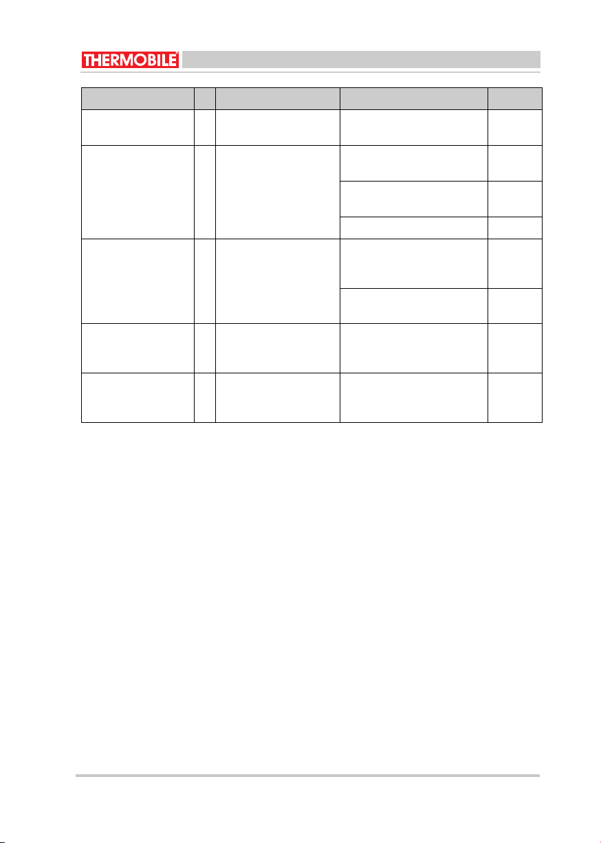
De heteluchtkachel
produceert witte rook.
20 Er is lucht in het
brandstofsysteem.
Zie storing: 6. Gebruiker
De heteluchtkachel
verbruikt te veel
brandstof.
21 De verstuiver is te groot
of van het verkeerde
type.
Vervang de verstuiver door
het juiste model.
Gebruiker
Controleer de koperleidin-
gen.
Gebruiker
Zie storingen: 10 en 18.
De heteluchtkachel
kan niet worden
uitgeschakeld.
22 De magneetklep sluit
niet.
Verwijder de koperleiding
van het filter om de vlam te
doven.
Gebruiker
Reinig of vervang de mag-
neetklep.
Dealer
De koelthermostaat
schakelt niet in/uit.
23 De automatische nakoe-
ling werkt niet.
Verwijder de koperleiding
van het filter: de vlam zal
doven.
Dealer
De automatische
nakoeling werkt niet /
stopt niet.
24 De nakoelthermostaat
schakelt niet in/uit.
Er moet 4 minuten gekoeld
worden. Trek daarna de ste-
ker uit de contactdoos.
Dealer
Storing Oorzaak Oplossing Actie
12 40.019.005 rev 00 - 2013 ITA 45/75 ROBUST 13
41.350.095 rev 01 - 2021
ITA 35 R

SATI/ATI1102-70.ver-500.020.0441
Nederlands
9 INSTALLATIE VAN ACCESSOIRES
9.1 Schoorsteen (fig. 4)
De heteluchtkachel heeft een aansluiting
voor een schoorsteen.
1. Schuif een passende schoorsteen (B)
over de aansluiting (C).
2. Plaats een regenkap (A) op het uiteinde
van de schoorsteen.
9.2 Luchtslang
Er kan een luchtslang aan de
uitblaasopening van de heteluchtkachel
worden gekoppeld, om op grote afstand van
de heteluchtkachel warme lucht te blazen.
/i
Neem contact op met de dealer voor
informatie over maximumlengtes van
uitblaasslangen, bochten, verdeelstukken en
slangklemmen.
9.3 Ruimtethermostaat
Zie de instructies voor de thermostaat.
9.4 Tankverwarming
Zie de instructies voor de tankverwarming.
10 EG-VERKLARING VAN
OVEREENSTEMMING
De EG-Verklaring van overeenstemming kunt
u vinden op www.thermobile.nl.
VOORZICHTIG
De schoorsteen moet naar boven
wijzen. Laat de schoorsteen nooit
horizontaal lopen. Een hoek van 45°
is aanvaardbaar; lengte schoorsteen
moet minimaal 1000 mm. zijn.
VOORZICHTIG
Controleer de temperatuurweerstand
van de gebruikte slang.
Enkele
uitblaas-
opening
ITA35 R
Max.
lengte
L = 6 m:
∅350mm
14 15
40.019.005 rev 00 - 2013
ITA 45/75 ROBUST
41.350.095 rev 01 - 2021 ITA 35 R
ITA/ITAS 40.020.005 - rev. 07 - 2011 15
English
English
Contents
Safety instructions..................................... 15
Introduction ............................................... 16
Getting started .......................................... 17
Operation .................................................. 17
Maintenance ............................................. 18
Troubleshooting ........................................ 19
Spare parts................................................ 21
Technical information ................................ 21
Installation of accessories......................... 22
EC Declaration of conformity .................... 22
Preface
This manual describes the use of the heaters
as mentioned on the cover. The information
in this manual is important for the correct and
safe use of the heater.
Identification of the product (fig. 1)
The identification plate is attached to the side
of the heater. The identification plate shows
the following data:
A Year of production
B Serial number
C Electrical connection
D Airflow
E Capacity
F Production code
Service and technical support
For information about the heater, please
contact your dealer or the manufacturer.
Make sure you have the type and serial
number of the heater.
Guarantee and liability
For the Guarantee and Liability see the terms
and conditions.
Environment
1 SAFETY INSTRUCTIONS
1.1 Pictograms in this manual
Note
The heater is made of various metals
and synthetic materials. The heater
also contains electronic parts, which
must be treated as electronic waste.
Please contact your dealer for further
information.
O
n
l
y app
li
ca
bl
e
t
o
th
e
E
uropean
Union
Waste disposal of electric &
electronic equipment for business
use.
For further information regarding the
disposal of products for business use
at the end of their life span, please
contact your dealer or distributor in
your country. This product may not
be disposed of together with
commercial waste or as commercial
waste.
Caution
A caution shows a danger that can
cause damage to the equipment.
Warning
A warning shows a hazard that can
cause death or serious injury.
Warning
When working on the heater for
maintenance or repair works always
disconnect the electric power!
Hot
Some surfaces are hot! Wait until
these parts are cooled down
sufficiently before maintenance is
carried out.
Suggestions and advice for
conducting the relevant tasks or
activities more easily.
14 40.019.005 rev 00 - 2013 ITA 45/75 ROBUST 15
41.350.095 rev 01 - 2021
ITA 35 R

SATI/ATI1102-70.ver-500.020.0461
English
1.2 Pictograms on the heater (fig. 2)
A Pump pressure
1.3 Use in conformity with destination
The heater is designed for use on
construction sites, in poultry houses,
workshops, storage rooms, warehouses,
greenhouses and polyurethane tunnels and
to dry agricultural products and bulbs.
1.4 General instructions
2 INTRODUCTION
2.1 Purpose
The heaters are indirectly fired heaters with
photocell control and connections for a room
thermostat and flue with raincover.
The heaters are tested at sea level and at a
temperature of 20 °C.
2.2 Operation principle
An electric motor drives a fan and fuel pump.
The pump draws the fuel from the tank to a
magnetic valve. The fan blows air into and
around the combustion chamber.
The magnetic valve opens 12 seconds after
switching on the heater and the fuel flows into
the nozzle.
A spark between the electrodes ignites the
atomised fuel and starts a flame. The light from
the flame activates a photocell. After the safety
time the ignition switches off. The magnetic
valve closes when you switch off the heater, or
as a result of a fault, the flame stops.
The fan runs until a thermostat switches the fan
off: the cooling cycle is complete.
2.3 Main components (fig. 2 and 3)
Grill
Fan
Electric motor
Magnetic valve
Electrode (2x)
Burner head
Air slide valve
Photocell
After cooling safety thermostat
Combustion chamber/heat exchanger
Flue connection
Maximum thermostat
On / off switch I-0-II
Reset button
Identification plate
Air inlet burner
Fuel pump
Connector for room thermostat
Cable with plug
Fuel filter
Push bar frame
2.4 Accessories
• Flue with raincover
• Room thermostat
• Single outlet with duct
•Manifold with duct
Warning
• Read this manual carefully before
you use the heater.
• Keep this document near the
heater.
• Do the procedures as written.
• Do not lean on the heater.
• Do not stand closer than 2 m
from the outlet of the heater.
• Make sure there is sufficient air
for good combustion.
• Keep all inflammable material
away from the heater.
• Only do repair and maintenance
after the heater has cooled
sufficiently and the heater is
disconnected from the electric
power.
16 17
40.019.005 rev 00 - 2013
ITA 45/75 ROBUST
40.019.006 rev 00 - 2017
ITA 35 R
40.019.006 rev 00 - 2017
ITA 35 R
41.350.095 rev 01 - 2021 ITA 35 R
A
B
C
D
E
F
G
H
I
J
K
L
M
N
O
P
Q
R
S
T
U
3
3.1
GETTING STARTED
Remove packaging
1. Remove the packaging from the heater.
3.2 Installation
1. Make sure that the heater is placed
horizontally.
2. Fill the tank with fuel.

711102-70.ver-500.020.04SATI/ATI
English
3. Make sure there is sufficient distance
between the wall and the air inlet.
Minimum distance is 1 m.
4. Make sure that the heated air can flow
without obstruction. Minimum distance
from outlet to an obstacle is 2 m.
5. Check the ventilation surface area: for
each kW a surface of 25 cm2 is needed.
6. Check the connection of the room
thermostat.
Do not remove the cap when you do not
use a room thermostat.
Remove the cap to connect a room
thermostat.
7. Install the flue (1 m and a raincover).
8. Make sure the I-0-II switch is in the 0
position.
9. Check the supply voltage: see the
identification plate.
10. Put the plug in the socket.
11. Press the reset switch.
3.3 Start heating.
Set the switch to position II to switch on the
heater.
2. Set the room thermostat.
The heater supplies warm air after
approximately 10 seconds.
4.1
4.2
1. Switch off the heater.
The magnet valve closes and stops the
fuel supply.
2. Disconnect the electric power.
Caution
Use only diesel oil or paraffin.
Caution
• Be careful when you fill the tank.
Remove any spilled oil from the
heater and the ground.
• Gas oil tends to thicken at low
temperatures. This can block the
filters. Add a maximum of 15%
paraffin to the fuel at
temperatures below -5 °C, or
keep the fuel frost-proof, or use
tank heating (optional).
Caution
Do not switch on the heater when the
tank is empty!
OPERATION
During operation
Hot
Do not touch the flue with rain cover,
nor the air outlet! The flue with rain
cover and the air outlet become hot
during operation!
Power down
Caution
After you switch off the heater, the
fan still rotates. The fan cools the
heater to avoid damage caused by
overheating. The fan stops
automatically.
Do not remove the plug from the
socket until the heater fully stops!
Caution
Do not disconnect the electric power
when using the tank heating.
16 40.019.005 rev 00 - 2013 ITA 45/75 ROBUST 17
41.350.095 rev 01 - 2021
ITA 35 R
3.3.1 Startup ventilation only
Set the switch to I to switch the
ventilation mode.
WARNING
Always use a filled diesel tank if the
machine operates in ventilation mode.
For pump damage due to dry running,
there is no warranty!
Caution
The fuel system de-aerates through the
nozzle. Close down may occur several
times when starting with an empty filter.
To rectify: press the reset switch.
4.

18 40.020.005 - rev. 07 - 2011 ITA/ITAS
English
5 MAINTENANCE
5.1 Maintenance table
After each winter season, record the
maintenance in the table at the back of this
book.
/i
5.2 General
If the heater is not used for a long period:
1. Empty the tank, rinse the tank with
paraffin.
2. Fill the tank with diesel oil, to prevent
corrosion in the tank.
3. Let the heater burn for 3 minutes. This
protects the pump against corrosion.
4. Keep the burner head free from dust and
sediment.
A dirty burner head causes bad
combustion that makes soot and carbon
and damage to the burner chamber.
5.3 Adjustment air inlet and
electrodes (fig. 6)
A Distance nozzle-swivel disc
B Opening air inlet
C Distance nozzle-electrode
5.4 Electrodes (fig. 7)
Check the electrodes:
1. Remove the cover of the heater.
2. Remove the oil pipe (B).
3. Loosen the electrode cables (A).
4. Remove the screws (G).
5. Remove the burner head (F).
6. Clean and re-adjust the electrodes (C).
The electrodes must be free of dirt,
grease, fuel etc.
If the points of the electrodes are burned
too much and adjustment is impossible:
replace the electrodes.
7. Loosen the screw (F).
8. Re-adjust the electrodes.
Install the burner head in the reverse order.
Description Period
Yearly Biennial
Empty the tank and rinse the tank with paraffin. X
Clean the filter in the filter cap of the tank. X
Check the photocell for damage. Make sure the photocell is free from
dust and sediment.
X
Check the adjustment of the electrodes. X
Replace the fuel filter. X
Check the nozzle. X
Clean the heat exchanger. X
Hot
Do not touch the flue with raincover
and air outlet! Wait until the flue with
raincover and the air are cooled
down before maintenance.
Warning
Disconnect the electric power during
maintenance.
18 ITA 35 R 19
40.019.005 rev 00 - 2013
ITA 45/75 ROBUST
41.350.095 rev 01 - 2021

ITA/ITAS 40.020.005 - rev. 07 - 2011 19
English
Replace the electrodes:
1. Do the points 1 to 7 of “Check the
electrodes”.
2. Replace the electrodes.
3. Adjust the electrodes.
Install the burner head in the reverse order.
5.5 Nozzle (fig. 7)
Check the nozzle:
1. Remove the cover of the heater.
2. Remove the oil pipe (B).
3. Loosen the electrode cables (A).
4. Remove the screws (G).
5. Remove the burner head (H).
6. Check the nozzle (D).
If the nozzle is black, because of soot or
coke: replace the nozzle.
Install the burner head in the reverse order.
Replace the nozzle:
1. Do the points 1 to 6 of “Check the
nozzle”.
2. Remove the electrodes (C).
3. Remove the swivel disc (E).
4. Remove the nozzle (D).
5. Replace the nozzle: use the correct type!
6. Install the swivel disc.
7. Readjust the electrodes, see fig. 6.
Install the burner head in the reverse order.
5.6 Photocell (fig. 5)
Check the photocell:
1. Remove the cover of the heater.
2. Remove the photocell out of the holder
pipe (A).
3. Clean the photocell if the glass is
black (B).
If the glass is cracked: the photocell must
be replaced by the dealer.
Install the photocell in the reverse order.
6 TROUBLESHOOTING
6.1 Table troubleshooting
/i
Warning
Do not touch the filter of the nozzle.
This will damage the nozzle.
Make sure that the electricity is
connected and the fuel tank is full
before you troubleshoot.
Warning
Disconnect the electric power during
repair!
Fault Cause Solution Action
The heater does not
start.
1 No cap is present on the
thermostat connection.
Fit the cap. User
2 The thermostat setting
is incorrect.
Correct the adjustment. User
3 The burner relay has a
fault.
Replace the burner relay. Dealer
4 The fan rotates irregu-
larly or is blocked.
Check the fuel pump.
Check the motor.
User
5 The fuel pump is
blocked.
Replace the fuel pump. Dealer
18 40.019.005 rev 00 - 2013 ITA 45/75 ROBUST 19
41.350.095 rev 01 - 2021
ITA 35 R
20 40.020.005 - rev. 07 - 2011 ITA/ITAS
English
The heater stops
burning. The reset
button is lit.
6 The fuel system has air
present when starting.
Press reset switch. Repeat
the start procedure if neces-
sary.
User
7 The fuel filter is blocked. Clean or replace the filter. User
8 The air inlet of the
burner has an incorrect
adjustment.
Adjust the air inlet, see fig. 6 Dealer
9 The magnetic valve
does not open.
Check the electrical connec-
tion. A “click” should be
heard when you press the
switch to “O” and “I”.
User
Clean or replace the mag-
netic valve.
Dealer
10 The pump pressure is
not correct.
Adjust the pump pressure
with a manometer.
Dealer
11 The pump coupling is
defective.
Replace the pump coupling. Dealer
12 The suction line or main
filter has an air leak.
Check and replace if neces-
sary.
User
13 The protection grill for
the air intake is dirty or
blocked.
Clean the grill. User
14 The fresh air supply is
not sufficient.
Open a door or a window. User
15 The photocell dirty. Clean the photocell, see
fig. 5.
User
16 The heat exchanger is
blocked.
Clean the heat exchanger. User
17 The overheating ther-
mostat is activated or
defective.
Trace cause. Reset, or if
necessary replace the ther-
mostat.
See faults 1 and 9.
User
The heater produces
smoke.
18 The nozzle is blocked or
worn.
Replace the nozzle. User
19 The suction line or main
filter has an air leak.
Check and replace if neces-
sary.
See faults 8, 10, 13 and 14.
User
Fault Cause Solution Action
20 21
40.019.005 rev 00 - 2013
ITA 45/75 ROBUST
41.350.095 rev 01 - 2021 ITA 35 R
Table of contents
Languages:
Other THERMOBILE Power Tools manuals


Popular Power Tools manuals by other brands


RTRMAX
RTRMAX RTH150 Original instruction manual

Ozito
Ozito OZMFS65WA instruction manual

National Flooring Equipment
National Flooring Equipment PANTHER 5280 instruction manual

EINHELL
EINHELL bavaria BRO 1200 E operating instructions

BGS technic
BGS technic 8301 quick start guide

Bosch
Bosch GSR 14 Original instructions