THERMOBILE GA-24 E User manual
GEBRUIKERSHANDLEIDING nUSER MANUAL nBEDIENUNGSANLEITUNG n
MANUAL DE L’UTILISATEUR nMANUAL DEL USUARIO n ИHCTPYKЦИЯ ПОЛЬЗОВАТЕЛЯ
GA-24(E)/GA-(P)42(E)/GA-(P)
60(E)/GA-(P)85(E)/GA(P)110(E)
2
40.020.947 - rev 06 - 2021 GA 24-42-60-85-110
2 40.020.947 - rev. 04 - 2011 GA 42-60-85-110
/i
- 1 - - 2 -
- 3 -
- 4 - - 5 -
CODE
Qn (Hs)
Qn (Hi)
Pgas
VERBR. / CONSUM
PROPAAN / PROPANE
TEMP.CLASSE / KLASSE / CLASS
230V / 50Hz / 0,60Amp. / 0,11 kW
16kg
PIN 63AQ4185
Fabr.year2007F0063
SERIE NR: Teller0
Made by THERMOBILE Industries B.V Breda Holland.
AT,FR,IE,LU,BE,GB,NL,DE,CH
40.277.000
14-44 kW
13-41 kW
0,4-1,5 Bar
1,0-3.1 kg/h
CAT.: I3p
A
IP44
K
L
C
B
A
D
E
F
I
H
G
JA B
C D
E
F
G
H I (4x)
A
B
A
B
C
D
G
E
F
A
G
D
E
F
C
B

3
40.020.947 - rev 06 - 2021
GA 24-42-60-85-110
GA 42-60-85-110 40.020.947 - rev. 04 - 2011 3
/i
- 6 -
- 7 - - 8 -
- 9 - - 10 -
DB E
F
G
I
J (4x)
A
C
H
A
E
C
B
D
A
B
A B
A

4
40.020.947 - rev 06 - 2021 GA 24-42-60-85-110
4 40.020.947 - rev. 04 - 2011 GA 42-60-85-110
/i
- 11 -
- 12 -
M
GA 110
Hmin
Hmin
M
M
Hmin
A
D
B
C

5
40.020.947 - rev 06 - 2021
GA 24-42-60-85-110
GA 42-60-85-110 40.020.947 - rev. 04 - 2011 5
Nederlands................................................... 6
English ....................................................... 16
Deutsch...................................................... 26
Français ..................................................... 37
Español ...................................................... 48
Русский язык............................................. 59

6
40.020.947 - rev 06 - 2021 GA 24-42-60-85-110
NEDERLANDS
6 40.020.947 - rev. 04 - 2011 GA 42-60-85-110
Nederlands
Nederlands
Inhoud
Veiligheidsinstructies ...................................7
Introductie....................................................8
Voorbereidingen...........................................9
Gebruik ......................................................10
Onderhoud.................................................10
Storingen....................................................12
Reserveonderdelen ...................................15
Technische informatie................................15
Installatie van accessoires.........................15
EG-Verklaring van overeenstemming ........15
Voorwoord
Deze handleiding bevat de
gebruiksaanwijzing voor de op de kaft
vermelde kachels. De informatie in deze
handleiding is belangrijk voor een juist en
veilig gebruik van de kachel.
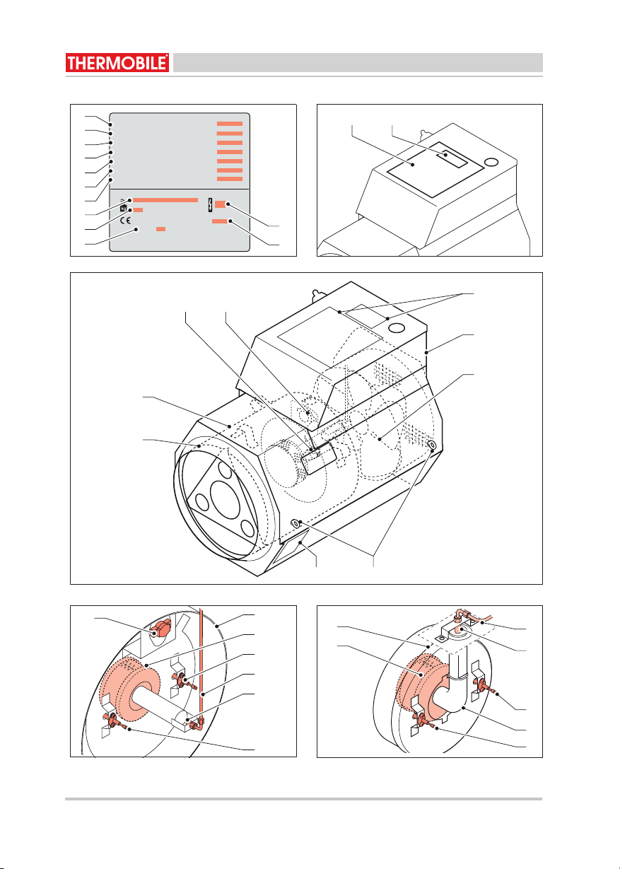
Identificatie van het product (fig. 1)
Het identificatieplaatje is bevestigd op de
zijkant van de kachel. Het identificatieplaatje
bevat de volgende gegevens:
A Jaar van fabricage
B Gewicht
C Spanningsgegevens
D Temperatuurklasse
E Gassoort
F Brandstofverbruik
G Branderdruk
H Capaciteit op de onderwaarde
I Capaciteit op de bovenwaarde
J Productie code
K Beschermingsgraad tegen stof en vocht
L Serienummer
Service en technische ondersteuning
Neem voor informatie over de kachel contact
op met uw dealer of met de fabrikant.
Zorg dat u de volgende gegevens bij de hand
hebt: type en serienummer van de kachel.
Garantie en aansprakelijkheid
Voor garantie en aansprakelijkheid, zie de
algemene garantiebepalingen.
Milieu
Let op
De kachel is gemaakt van diverse
metalen en kunststoffen. De kachel
bevat tevens elektronische
onderdelen, die als elektronisch afval
moeten worden behandeld. Neem
contact op met uw dealer voor
nadere informatie.
All
een van
t
oepass
i
ng
i
n
d
e
Europese Unie
Afvalverwijdering van elektrische
& elektronische apparatuur voor
zakelijk gebruik.
Voor nadere informatie aangaande
het wegwerpen van producten voor
zakelijke doeleinden aan het einde
van hun levensduur, wordt u verzocht
contact op te nemen met uw dealer
of distributeur in uw land. Dit product
mag niet samen met of in de vorm
van commercieel afval worden
weggegooid.
7
40.020.947 - rev 06 - 2021
GA 24-42-60-85-110
NEDERLANDS
GA 42-60-85-110 40.020.947 - rev. 04 - 2011 7
Nederlands
1 VEILIGHEIDSINSTRUCTIES
1.1 Pictogrammen in deze handleiding
1.2 Pictogrammen op de kachel (fig. 2)
A Gebruikersinstructie
B Gegevens brandstofverbruik
1.3 Gebruik dit product waarvoor het
bestemd is
De in deze handleiding beschreven kachels
zijn geschikt voor verwarming met
propaangas.
De kachels zijn ontworpen voor:
• Drogen van nieuwbouw.
• Gericht verwarmen van werkplaatsen in
een brandveilige omgeving.
• Verwarmen van voldoende geventileerde
ruimten.
• Ontdooien van leidingen, installaties,
apparaten en goederen in niet
brandgevaarlijke situaties.
• Vorstbewaking in industrie, bouw en
tuinbouwtunnels.
1.4 Algemene instructies
VOORZICHTIG
Wijst op gevaar voor beschadiging
van de apparatuur.
WAARSCHUWING
Wijst op een gevaarlijke situatie, die
de dood of ernstige verwondingen tot
gevolg kan hebben.
WAARSCHUWING
Schakel bij onderhouds- of
reparatiewerkzaamheden aan de
heteluchtkachel altijd de elektrische
stroom uit!
Heet
Sommige vlakken kunnen heet zijn!
Wacht met onderhoud totdat deze
onderdelen voldoende zijn afgekoeld.
Suggesties en tips om de uitvoering
van de betreffende taken of
handelingen te vereenvoudigen.
WAARSCHUWING
• Lees deze handleiding
zorgvuldig door, alvorens de
kachel te gebruiken.
• Bewaar dit document bij de
kachel.
• Volg de beschreven procedures.
• Leun nooit op de kachel.
• Zorg dat er licht ontvlambaar
materiaal op minimaal 3 m
afstand van de kachel blijft.
• Zet de kachel niet op een
brandbare vloer.
• Zorg dat er voldoende lucht is
voor een goede verbranding.
• Voer uitsluitend reparatie- en
onderhoudswerkzaamheden uit
als de kachel voldoende is
afgekoeld, en nadat de steker uit
de contactdoos is verwijderd.
• Zorg dat er brandblusapparatuur
in de buurt van de kachel is.
• De gasaansluiting moet voldoen
aan de plaatselijk geldende
voorschriften.
• Gasflessen uitsluitend rechtop
gebruiken.
• Gasflessen niet in de hete
luchtstroom plaatsen.

8
40.020.947 - rev 05 - 2016 GA 24-42-60-85-110
NEDERLANDS
011-58-06-24AG1102-40.ver-749.020.048
Nederlands
2 INTRODUCTIE
2.1 Doel
Deze kachels zijn direct propaangas
gestookte kachels met een aansluiting voor
een gasfles met drukregelaar.
De kachels zijn uitgevoerd met een
warmeluchtventilator en een aansluiting voor
een ruimtethermostaat.
De kachels zijn getest op zeeniveau bij een
temperatuur van 20 °C.
2.2 Werkingsprincipe
Wanneer de schakelaar op stand 1 wordt
gezet, start de ventilator. De elektrische
ontsteking wordt geactiveerd en na enige tijd
schakelt het magneetventiel de gastoevoer
naar de brander in.
Het gas wordt bij de ingang van de brander
vermengd met lucht. Het mengsel wordt met
een elektrische vonk ontstoken. Door middel
van de ionisatiepen wordt gecontroleerd of er
binnen enkele seconden een vlam ontstaat.
Indien er binnen de beveiligingstijd geen
vlam ontstaat, valt de kachel in storing. De
ontsteking stopt automatisch zodra een
goede vlam gevormd is.
De kachel is uitgerust met een
branderautomaat die automatisch de
ontsteking en de gastoevoer regelt. De
capaciteit kan naar behoefte ingesteld
worden door het handmatig instellen van de
toegevoerde hoeveelheid gas. De capaciteit
kan ook geregeld worden met een
modulerende regeling, raadpleeg de dealer
voor meer informatie.
De kachel is voorzien van een maximaal
thermostaat, die bij oververhitting de
gastoevoer onderbreekt. De thermostaat kan
na afkoeling handmatig gereset worden.
Achter de branderkamer bevindt zich nog
een extra maximaalthermostaat die na
afkoeling automatisch gereset wordt (alleen
GA 42).
Bij storing schakelt de branderautomaat de
kachel uit. Daarbij gaat de rode lamp op het
bedieningspaneel branden.
Op de uitgaande zijde van de drukregelaar is
een slangbreukbeveiliging gemonteerd, die
bij slangbreuk de gastoevoer onderbreekt.
De kachel stopt zodra de keuzeschakelaar
op het bedieningspaneel op “0” gezet wordt.
De kachel kan als ventilator gebruikt worden,
door de keuzeschakelaar op het
bedieningspaneel op stand 2 te zetten.
2.3 Hoofdcomponenten GA 24/42 (fig. 3)
A Uitblaasrooster
B Branderkamer
C Thermostaat met resetknop
D Thermostaat met automatische reset
E Pictogrammen
F Bedieningspaneel
G Warmeluchtventilator
H Typeplaatje
I Hijsoog
2.4 Hoofdcomponenten GA 60-85-110
(fig. 6)
A Uitblaasrooster
B Branderkamer
C Thermostaat met resetknop
D Aansluiting buitenluchttoevoer
E Pictogrammen
F Bedieningspaneel
G Warmeluchtventilator
H Verrijdbaar onderstel
I Typeplaatje
J Ophangoog
2.5 Hoofdcomponenten branderkamer
GA 24/42 (fig. 4)
A Branderkamer
B Brander
C Ionisatiepen
D Gastoevoerleiding
E Verstuiver
F Ontstekingspen
G Thermostaat met automatische reset

9
40.020.947 - rev 06 - 2021
GA 24-42-60-85-110
NEDERLANDS
GA 42-60-85-110 40.020.947 - rev. 04 - 2011 9
Nederlands
2.6 Hoofdcomponenten branderkamer
GA 60-85-110 (fig. 5)
A Branderkamer
B Gastoevoerleiding
C Verstuiver
D Ionisatiepen
E Luchttoevoerleiding
F Ontstekingspen
G Brander
2.7 Bedieningspaneel (fig. 7)
A Resetknop + controlelamp
B Gasaansluiting
C Aansluiting ruimtethermostaat
D Aansluitsnoer
E Keuzeschakelaar:
- 0 = Uit
- 1 = Verwarmen
- 2 = Ventileren (niet verwarmen)
2.8 Accessoires
• Ruimtethermostaat
• Slang buitenluchtaanzuiging
• Buitenluchtdoorvoer
• Verrijdbaar onderstel (GA 60 en GA 85)
3 VOORBEREIDINGEN
3.1 Verpakking verwijderen
1. Verwijder de verpakking van de kachel.
3.2 Installatie
1. Zorg voor een stabiele opstelling van de
kachel.
2. Hang de kachel aan de ophangogen op.
3. Sluit de meegeleverde gasslang met de
drukregelaar (A) en
slangbreukbeveiliging (B) aan op de
gasfles, voor GA 42 zie fig. 8, voor GA
60-85-110 zie fig. 9.
De kachel kan zowel horizontaal als
vertikaal (omhoog- of
omlaagblazend) worden geplaatst.
Neem bij het plaatsen van de kachel
de minimale afstanden (Hmin) tot de
vloer en het plafond in acht (zie fig.
11).
• Horizontaal: minimaal 0.2 m
boven de vloer.
• Vertikaal omlaagblazend:
minimaal 2.15 m boven de vloer
(voor GA 110 minimaal 1.70 m).
• Vertikaal omhoogblazend:
minimaal 2.15 m onder het
plafond (voor GA 110 minimaal
1.70 m).
• Het magneetventiel M (zie fig. 11)
dient altijd in verticale positie
geplaatst te worden (raadpleeg
uw dealer).
WAARSCHUWING
• De kachel uitsluitend aansluiten
op de gasfles met de
bijgeleverde slang met
drukregelaar en
slangbreukbeveiliging.
• Gasflessen uitsluitend rechtop
gebruiken.
• Gasflessen niet in de hete
luchtstroom plaatsen.
10
40.020.947 - rev 05 - 2016 GA 24-42-60-85-110
NEDERLANDS
10 40.020.947 - rev. 04 - 2011 GA 42-60-85-110
Nederlands
4. Sluit de andere zijde van de slang aan op
de gastoevoer van de kachel.
5. Indien de kachel wordt voorzien van een
ruimtethermostaat, sluit deze aan op de
daarvoor bestemde aansluiting (C) van
het bedieningspaneel, zie fig. 7. Deze
aansluiting is standaard voorzien van een
steker waarop de contacten zijn
doorverbonden.
6. Voor het aansluiten van een buitenlucht
toevoer, zie hoofdstuk 9.
3.3 Voorbereiden voor opstarten
1. Zet de keuzeschakelaar op stand 0.
2. Steek de steker in de contactdoos.
3.4 Opstarten
Verwarmen:
1. Draai de afsluiter op de gastoevoer open.
2. Druk op de knop van de
slangbreukbeveiliging.
3. Zet de keuzeschakelaar (fig. 7E) op de
stand 1.
4. Stel de capaciteit in met behulp van de
regelaar op de gasaansluiting (zie grafiek
in appendix B).
Ventileren:
1. Zet de keuzeschakelaar (fig. 7E) op de
stand 2.
4 GEBRUIK
4.1 Tijdens bedrijf
4.2 Uitschakelen
1. Zet de keuzeschakelaar (fig. 7E) op de
stand 0.
2. Draai de afsluiter op de gastoevoer dicht.
5 ONDERHOUD
5.1 Algemeen
Als de kachel voor langere tijd opgeslagen
wordt:
1. Schakel de kachel uit.
2. Sluit de gastoevoer af.
3. Neem de netspanningssteker uit de
contactdoos.
4. Reinig de kachel.
5.2 Onderhoudstabel
Registreer na elk winterseizoen het
onderhoud in de tabel achterin dit boek.
Verwijder het onderste deel van de kap voor
het plegen van onderhoud aan inwendige
onderdelen.
Draai de steker in de contactdoos
om, indien de rode controlelamp (fig.
7A) op het bedieningspaneel brandt.
De steker moet altijd bereikbaar zijn.
Heet
Raak de uitblaasopening niet aan!
De uitblaasopening wordt heet tijdens
bedrijf!
WAARSCHUWING
Sluit de gastoevoer af en haal de
steker uit de contactdoos bij
werkzaamheden aan de kachel.
Heet
Raak de uitlaat en de branderkamer
niet aan!
Wacht met het onderhoud totdat
deze zijn afgekoeld.
11
40.020.947 - rev 06 - 2021
GA 24-42-60-85-110
NEDERLANDS
111102-40.ver-749.020.04011-58-06-24AG
Nederlands
/i
5.3 Afstellen ontstekingspen
1. Verwijder het rooster van de
uitblaasopening (GA 60-85-110). De
ontstekingspen is bereikbaar via de
uitblaasopening.
2. Controleer de afstand tussen de
ontstekingspen en de brander en indien
nodig, stel deze af op de juiste afstand A
(zie fig. 10).
/i
3. Monteer het rooster.
Beschrijving Periode
Iedere
week
Iedere
maand
Ieder
half
jaar
Ieder
jaar
Verwijder stof en aanslag van de kachel. X
relaeD.)gnivegmoenohcsneeni(lehcakedreelortnoC
Controleer de kachel (in relaeD.)gnivegmoegiffotsnee
Controleer en reinig de toevoeropening voor de verbran-
dingslucht (GA 60-85-110).
X
X.retsoortaalnitehginiernereelortnoC
Controleer de warmeluchtventilator op werking en bescha-
digingen.
X
Controleer de kachel op een juiste verbranding. De vlam
moet blauw zijn. Indien de vlam geel is, raadpleeg de dea-
ler.
X
Reinig de branderkop met een staaldraadborstel en pers-
lucht.
X
Reinig de verstuiver en de injectieopening. X
Reinig de ionisatiepen en de ontstekingspen met staalwol. X
Controleer de afstelling van de ontstekingspen en stel
deze zonodig bij, zie 5.3 "Afstellen ontstekingspen".
X
X
X.lehcakednavgnidardebedreelortnoC
Controleer de gasslang op beschadiging en vervang deze,
Controleer stoffilter van luchtdrukschakelaar bij
P-uitvoering.
indien nodig. De gasslang dient minimaal elke twee jaar
vervangen te worden.
X
GA 24/42 GA 60-85-110
3 mm 4 mm

12
40.020.947 - rev 06 - 2021 GA 24-42-60-85-110
NEDERLANDS
011-58-06-24AG1102-40.ver-749.020.0421
Nederlands
6 STORINGEN
6.1 Tabel storingzoeken
/i
Zorg dat de netspanning
ingeschakeld is en de gastoevoer
geopend is, tijdens het
storingzoeken.
Verwijder het onderste deel van de
buitenmantel (GA42) en het bovenste
deel van de buitenmantel (GA 60/85/
110) voor het plegen van onderhoud
aan de inwendige onderdelen.
WAARSCHUWING
Neem de netspanningssteker uit de
contactdoos en sluit de gastoevoer
tijdens een reparatie.
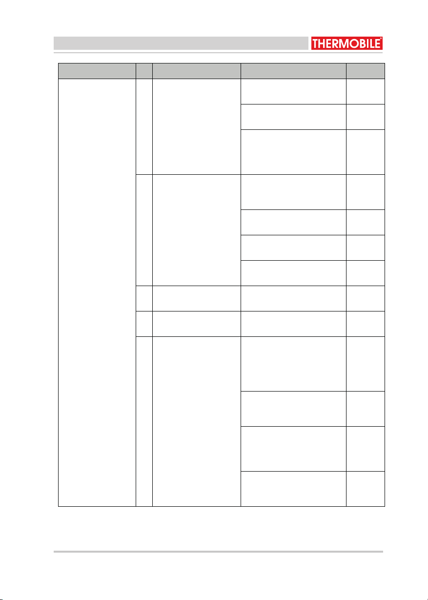
Storing Oorzaak Oplossing Actie
De kachel start niet. 1 De kachel heeft geen
spanning.
Controleer de elektrische
aansluiting.
Gebruiker
2 De ventilatormotor
draait zwaar of is
geblokkeerd.
Controleer of de ventilator-
motor vervuild of geblok-
keerd is .
Gebruiker
Vervang de ventilatormotor. Dealer
3 De thermostaat is inge-
steld op een te lage
temperatuur.
Corrigeer de instelling. Gebruiker
4 Er zit geen doorverbin-
dingsconnector op de
thermostaat aansluiting.
Breng de doorverbindings-
connector aan.
Gebruiker
GebruikerVervang filter6
7
8
5 Defect in het bedie-
ningspaneel
Repareer of vervang het
bedieningspaneel
Dealer
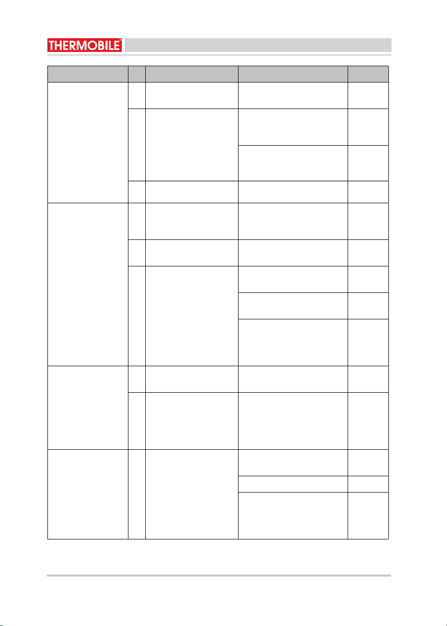
De kachel gaat in
storing; de rode en
gele lamp op het
bedieningspaneel
branden.
De netsteker zit ver-
Filter bij de luchtdruk-
verschilschakelaar is vuil
keerd om in de contact-
doos.
Draai de steker om. Gebruiker
De aarde van de con-
tactdoos is niet in orde.
Laat de aarde van de con-
tactdoos controleren door
een erkend installateur.
Gebruiker
De kachel gaat in
storing; de rode lamp
op het bedieningspa-
neel brandt.
13
40.020.947 - rev 06 - 2021
GA 24-42-60-85-110
NEDERLANDS
311102-40.ver-749.020.04011-58-06-24AG
Nederlands
De kachel gaat in
storing: de rode lamp
op het bedienings-
paneel brandt.
Er is geen of te weing
gasdruk voor de mag-
neetkleppen.
Controleer of de afsluiter op
de gasfles geopend is.
Gebruiker
Controleer of de gasfles leeg
is.
Gebruiker
Druk op de knop van de
slangbreukbeveiligingen op
de resetknop van het bedie-
ningspaneel.
Gebruiker
De magneetkleppen
openen niet.
Druk op de resetknop van de
maximaalthermostaat en van
het bedieningspaneel.
Gebruiker
Controleer de maximaalther-
mostaat.
Dealer
Controleer de magneetklep-
pen.
Dealer
Controleer de elektrische
aansluiting.
Dealer
De ionisatiepen is vuil. Reinig de ionisatiepen met
staalwol.
Gebruiker
Het beschermgaas voor
de ventilator is vervuild.
Reinig het beschermgaas. Gebruiker
De maximaalthermos-
9
10
11
12
13
taat is uitgeschakeld.
Controleer het aanzuigroos-
ter en de uitblaasopening op
vervuiling en op voldoende
ruimte voor een vrije door-
stroming.
Gebruiker
Druk op de resetknop van de
maximaalthermostaat en van
het bedieningspaneel.
Gebruiker
Controleer of de ventilator
zwaar draait of geblokkeerd
is. Raadpleeg zonodig de
dealer.
Gebruiker
Controleer de goede wer-
king van de ventilator. Indien
nodig, vervang de ventilator.
Dealer
Storing Oorzaak Oplossing Actie
14
40.020.947 - rev 05 - 2016 GA 24-42-60-85-110
NEDERLANDS
011-58-06-24AG1102-40.ver-749.020.0441
Nederlands
Noteer de onderhoudsgegevens in tabel A in
de annex achterin dit boek.
De kachel gaat in
storing: de rode lamp
op het bedienings-
paneel brandt.
De maximaalthermos-14
15
16
17
18
19
20
21
22
taat is defect.
Vervang de maximaalther-
mostaat.
Dealer
De ontsteking werkt
Luchtdrukverschilscha-
kelaar heeft geschakeld
Controleer
luchtdrukschakelaar
niet.
Controleer de verbinding tus-
sen de trafo en de ontste-
kingspen op kortsluiting.
Gebruiker
Controleer de afstelling van
de ontstekingspen (zie
“Afstellen ontstekingspen”).
Gebruiker
Gebruiker
De gastoevoer wordt
onderbroken tijdens
bedrijf, de vlam gaat
uit.
De thermostaat is inge-
steld op een te lage
temperatuur.
Corrigeer de instelling. Gebruiker
Defect in het bedie-
ningspaneel.
Repareer of vervang het
bedieningspaneel.
Dealer
Er is geen of te weinig
gasdruk voor de mag-
neetkleppen.
Controleer of de afsluiter op
de gasfles geopend is.
Gebruiker
Controleer of de gasfles leeg
is.
Gebruiker
Druk op de knop van de
slangbreukbeveiligingen op
de resetknop van het bedie-
ningspaneel.
Gebruiker
De kachel gebruikt te
veel gas.
De drukregelaar is
defect.
Vervang de drukregelaar. Gebruiker
Er is een lek in de
brandstofleiding tussen
de gasfles en de gas-
aansluiting op de
kachel.
Spoor het lek op met zeep-
sop. Vervang het defecte
onderdeel.
Gebruiker
De kachel is met de
schakelaar niet uit te
schakelen.
De magneetkleppen
sluiten niet of de scha-
kelaar is defect.
Sluit de gastoevoer af en laat
de vlam uitbranden.
Gebruiker
Neem de netaansluiting los. Gebruiker
Controleer de magneetklep-
pen en de schakelaar en
indien nodig, vervang het
defecte onderdeel.
Dealer
Storing Oorzaak Oplossing Actie

15
40.020.947 - rev 06 - 2021
GA 24-42-60-85-110
NEDERLANDS
GA 42-60-85-110 40.020.947 - rev. 04 - 2011 15
Nederlands
7 RESERVEONDERDELEN
Raadpleeg de dealer voor het gebruik van
reserveonderdelen.
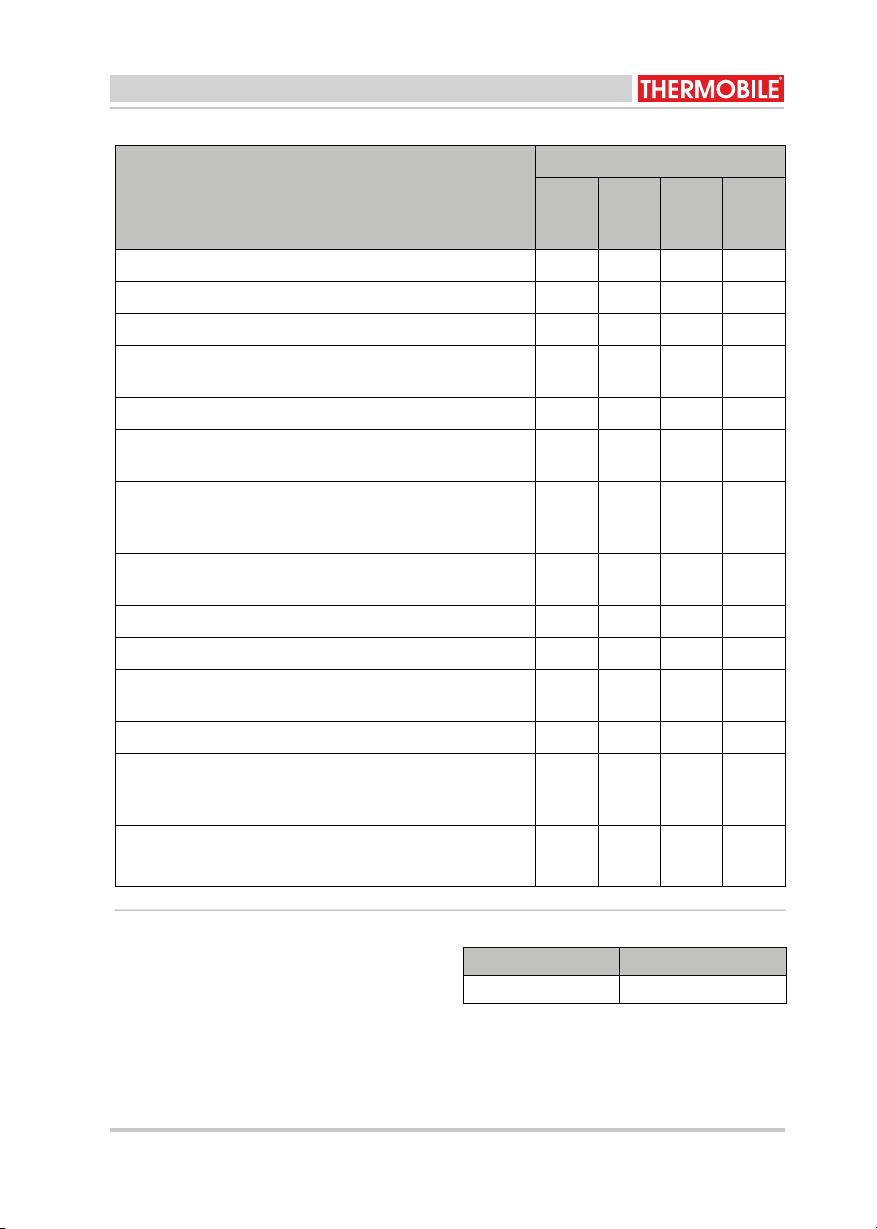
8 TECHNISCHE INFORMATIE
• Zie voor de technische specificaties tabel
B in de annex achterin dit boek.
9 INSTALLATIE VAN ACCESSOIRES
9.1 Buitenlucht aanzuigset (fig. 12)
De verbrandingslucht kan direct van buiten
komen bij de toepassing van een slang met
wanddoorvoer.
1. Maak een gat in de muur voor de
plaatsing van de wanddoorvoer (A).
2. Schuif het ene uiteinde van de slang (B)
op de inlaat van de kachel (C).
3. Schuif het andere uiteinde op de
aansluiting van de wanddoorvoer (D).
4. Zet de slang aan beide zijden met
slangklemmen vast.
9.2 Aansluitdiameter luchtslang
De aansluiting op de kachel heeft een
diameter van 100 mm.
10 EG-VERKLARING VAN
OVEREENSTEMMING
De EG-Verklaring van overeenstemming kunt
uvinden op www.thermobile.nl.
De luchtslang mag maximaal 6 m
lang zijn.
16
40.020.947 - rev 06 - 2021 GA 24-42-60-85-110
ENGLISH
16 40.020.947 - rev. 04 - 2011 GA 42-60-85-110
English
English
Contents
Safety instructions .....................................17
Introduction................................................18
Preparations ..............................................19
Use ............................................................20
Maintenance ..............................................20
Faults .........................................................22
Spare parts ................................................25
Technical information.................................25
Installing accessories.................................25
EC Declaration of conformity .....................25
Preface
This manual contains the instructions for use
of the heaters shown on the cover. The
information in this manual is important for the
correct and safe use of the heater.
Identification of the product (fig. 1)
The identification plate is attached to the side
of the heater. The identification plate contains
the following data:
A Year of manufacture
B Weight
C Voltage data
D Temperature class
E Type of gas
F Fuel consumption
G Burner pressure
H Capacity on the lowest value
I Capacity on the highest
J Production code
K Protection level against dust and
moisture
L Serial number
Service and technical support
Please contact your dealer or the
manufacturer for information about the
heater. Make sure you have the following
data at hand: type and serial number of the
heater.
Warranty and liability
For warranty and liability, see the general
warranty regulations.
Environment
Note
The heater is made of various metals
and synthetic materials. The heater
also contains electronic parts, which
must be treated as electronic waste.
Please contact your dealer for further
information.
O
n
l
y app
li
ca
bl
e
t
o
th
e
E
uropean
Union
Waste disposal of electric &
electronic equipment for business
use.
For further information regarding the
disposal of products for business use
at the end of their life span, please
contact your dealer or distributor in
your country. This product may not
be disposed of together with
commercial waste or as commercial
waste.

17
40.020.947 - rev 06 - 2021
GA 24-42-60-85-110
ENGLISH
GA 42-60-85-110 40.020.947 - rev. 04 - 2011 17
English
1 SAFETY INSTRUCTIONS
1.1 Pictograms in this manual
1.2 Pictograms on the heater (fig. 2)
A User instructions
B Fuel consumption data
1.3 Use this product for its intended
use
The heaters described in this manual are
suitable for heating using propane gas.
The heaters have been designed for:
• Drying newly built buildings.
• Specific heating of workshops in a fire-
safe environment.
• Heating of sufficiently ventilated rooms.
• Defrosting pipes, installations, appliances
and goods in situations in which there is
no danger of fire.
• Frost protection in industry, construction
and tunnels in horticulture.
1.4 General instructions
Caution
Indicates risk of damage to the
appliance.
Warning
Indicates a dangerous situation that
may lead to death or serious injuries.
Warning
Always switch off power when
performing maintenance or repairs on
the convector heater!
Hot
Some surfaces may be hot! Wait until
these parts have sufficiently cooled
down before performing
maintenance.
Suggestions and tips to facilitate the
specified tasks or actions.
Warning
• Read this manual carefully
before using the heater.
• Keep this document with the
heater.
• Follow the described procedures.
• Never lean against the heater.
• Keep highly inflammable
materials at a minimum distance
of 3 m from the heater:
• Do not put the heater on an
inflammable floor.
• Make sure there is enough air for
good combustion.
• Only perform repair and
maintenance activities when the
heater has sufficiently cooled
down and after removing the plug
from the socket.
• Make sure there is fire-
extinguishing equipment near the
heater.
• The gas connection must comply
with the applicable local
regulations.
•Use gas bottles exclusively in a
standing position.
• Do not place the gas bottles in
the hot air flow.

18
40.020.947 - rev 06 - 2021 GA 24-42-60-85-110
ENGLISH
011-58-06-24AG1102-40.ver-749.020.0481
English
2 INTRODUCTION
2.1 Purpose
These heaters are directly propane gas-fired
heaters with a connection for a gas bottle
with pressure controller.
The heaters are equipped with a hot air fan
and a connection for a room thermostat.
The hot air heaters have been tested at sea
level at a temperature of 20 °C.
2.2 Working principle
When the switch is set to position 1, the fan
will start. The electrical ignition is activated
and, after some time, the magnet valve will
switch on the gas supply to the burner.
The gas will be mixed with air when entering
the burner. The mixture is ignited with an
electrical spark. An ionisation pin is used to
check if a flame occurs within a few seconds.
If there is no flame within the prescribed time,
the heater triggers a fault. The ignition stops
automatically as soon as good flame has
been formed.
The heater has been equipped with a burner
automat that automatically controls the
ignition and the gas supply. The capacity can
be set as needed by manually setting the
supplied amount of gas. The capacity can
also be controlled by a modulating control.
Contact the dealer for additional information.
The heater has been equipped with a
maximum thermostat that interrupts the gas
supply in case of overheating. The
thermostat can be reset manually after
cooling down. An extra maximum thermostat
can be found behind the combustion
chamber. This can be automatically reset
after cooling down (only GA 42).
In case of a fault, the burner automat will
switch off the heater. The red lamp on the
operating panel lights up now.
A hose-breaking protection has been
mounted on the output side of the pressure
controller. This will interrupt the gas supply in
case the hose breaks.
The heater stops when the selector switch on
the operating panel is set to “0”. The heater
can be used as a fan by setting the selector
switch on the operating panel to position 2.
2.3 Main components GA 24/42 (fig. 3)
A Blower grate
B Combustion chamber
C Thermostat with reset button
D Thermostat with automatic reset
E Pictograms
F Operating panel
G Hot air fan
H Type plate
I Lifting hook
2.4 Main components GA 60-85-110
(fig. 6)
A Blower grate
B Combustion chamber
C Thermostat with reset button
D Connection outside air supply
E Pictograms
F Operating panel
G Hot air fan
H Moveable undercarriage
I Type plate
J Suspension eye
2.5 Main components combustion
chamber GA 24/42 (fig. 4)
A Combustion chamber
B Burner
C Ionisation pin
D Gas supply line
E Nozzle
F Ignition pin
G Thermostat with automatic reset
2.6 Main components combustion
chamber GA 60-85-110 (fig. 5)
A Combustion chamber
B Gas supply line
C Nozzle
D Ionisation pin
E Air supply line
F Ignition pin
G Burner

19
40.020.947 - rev 06 - 2021
GA 24-42-60-85-110
ENGLISH
GA 42-60-85-110 40.020.947 - rev. 04 - 2011 19
English
2.7 Operating panel (fig. 7)
A Reset button + indicator
B Gas connection
C Connection point for room thermostat
D Connection cable
E Selector switch:
- 0 = Off
- 1 = Heat
- 2 = Ventilate (not heat)
2.8 Accessories
• Room thermostat
• Outside air suction hose
• Outside air feed-through
• Moveable undercarriage (GA 60 and GA
85)
3 PREPARATIONS
3.1 Removing the packaging
1. Remove packaging from the heater.
3.2 Installation
1. Make sure that the heater has a stable
set-up.
2. Hang the heater on the suspension eyes.
3. Connect the delivered gas hose with the
pressure controller (A) and the hose-
breaking protection (B) to the gas bottle,
for GA 42 see fig. 8, for GA 60-85-110
see fig. 9.
4. Connect the other side of the hose to the
gas supply of the heater.
The heater can be positioned both
horizontally and vertically (blowing up
or down).
When positioning the heater, take the
minimum distances (Hmin) unto the
floor and the ceiling into account (see
fig. 11).
• Horizontal: a minimum of 0.2 m
above the floor.
• Vertically blowing down: a
minimum of 2.15 m above the
floor (for GA 110 min. 1.70 m).
• Vertically blowing up: a minimum
of 2.15 m below the ceiling (for
GA 110 min. 1.70 m).
• Always place the magnet valve M
(see fig. 11) vertically (contact
your dealer).
Warning
• Connect the heater exclusively to
the gas bottle using the delivered
hose with pressure controller and
hose-breaking protection.
• Use gas bottles exclusively in a
standing position.
• Do not place the gas bottles in
the hot air flow.
20
40.020.947 - rev 06 - 2021 GA 24-42-60-85-110
ENGLISH
20 40.020.947 - rev. 04 - 2011 GA 42-60-85-110
English
5. If the heater is provided with a room
thermostat, connect this to the
appropriate connection (C) of the
operating panel, see fig. 7. This
connection has as a rule been provided
with a plug to which the contacts are
connected.
6. See chapter 9 for connecting an outside
air supply.
3.3 Prepare for start-up
1. Set the selector switch to position 0.
2. Insert the plug into the socket.
3.4 Start up
Heat:
1. Open the shut-off valve on the gas
supply.
2. Press the button of the hose-breaking
protection.
3. Set the selector switch (fig. 7E) to
position 1.
4. Set the capacity using the controller on
the gas connection (see diagram in
annex B).
Ventilate:
1. Set the selector switch (fig. 7E) to
position 2.
4 USE
4.1 During operation
4.2 Switch off
1. Set the selector switch (fig. 7E) to
position 0.
2. Close the shut-off valve on the gas
supply.
5 MAINTENANCE
5.1 General
For long-term storage of the heater:
1. Switch off the heater.
2. Shut off the gas supply.
3. Remove the mains plug from the socket.
4. Clean the heater.
5.2 Maintenance table
Use the table in this manual to record the
maintenance after each winter.
Remove the bottom part of the cap for
maintenance on the internal parts.
Reverse the connector in the socket if
the red indicator lamp (fig. 7A) lights
up on the operating panel.
The plug must always be accessible.
Hot
Do not touch the flue and outlet
openings!
They will become hot during
operation!
Warning
Shut off the gas supply and take the
plug from the socket when working
on the heater.
Hot
Do not touch the outlet or combustion
chamber!
Do not start maintenance until they
have cooled down.
This manual suits for next models
4
Table of contents
Languages:
Other THERMOBILE Power Tools manuals


