Tradesman MAGNESIUM 8520 User manual

TRADESMAN
®
MAGNESIUM SERIES
OWNERS MANUAL
18 Gauge
1/4” Crown Stapler
Model #8520
CAUTION - FOR YOUR OWN SAFETY
READ YOUR OWNER'S MANUAL THROUGH COMPLETELY AND
CAREFULLY BEFORE ATTEMPTING TO SET-UP OR OPERATE YOUR
NEW AIR TOOL. READ AND UNDERSTAND ALL SAFETY RULES.
Your new Pneumatic Tool is a well built, carefully inspected and versatile
product, capable of giving you many years of dependable service. It comes
complete in one carton with a minimum of final assembly and setup required
by you. When unpacking, be sure to check all packages and packing material
for loose parts before discarding.
NOTICE: On the nameplate of your machine you will find the serial number of
your unit. Record this number on this manual cover for future reference.
SERIAL # __________ MFG. DATE # _________ PURCHASE DATE: __________
POWER TOOL SPECIALISTS, INC. E. WINDSOR, CT 06088 PRINTED IN TAIWAN
“LIMITED” TWO YEAR WARRANTY POLICY
All current model TRADESMAN air tools manufactured by POWER TOOL SPECIALISTS are
warranted to the original purchaser thereof to be free from defects in material used in their
manufacture or workmanship for a period of TWO years from the date of initial retail purchase. Labor
on warranted parts will be covered for a period of ONE year. This warranty does not cover any parts
that have been subjected to misuse, abuse, alteration, overload, accident or normal wear of moving
parts. Any machine or part that is returned to us, together with a sales slip or other proof of date of
initial retail purchase, postage prepaid, will be repaired or replaced without cost if the unit is found
defective. Such repairs or replacement will be made within a reasonable time. (not exceeding 60
days following receipt by POWER TOOL SPECIALISTS)
Only POWER TOOL SPECIALISTS is authorized to perform warranty service to its products.
This warranty gives you specific legal rights. You also have implied warranty rights. In the event you
have a problem with this warranty service or performance, you may be able to go to Small Claims
Court, a State Court or a Federal District Court.
How to Obtain Replacement Parts and Service
The merchandise you have purchased from us has been carefully engineered and manufactured
under POWER TOOL SPECIALISTS rigid quality standards and should give you satisfactory and
dependable operation. However, like all mechanical merchandise, it may occasionally require
adjustment, replacement parts, or maintenance. Should you ever need assistance or parts, please
contact or write your nearest authorized service center or the National Parts & Service Center.
DO NOT RETURN THIS PRODUCT TO THE YOUR LOCAL DEALER
PROVIDE THE FOLLOWING INFORMATION: 6. Do not return the product to us unless you have first
1. Model and serial number found on nameplate. obtained a Return Authorization Number (RA#) and
2. The date and store name from which you ship to address.
purchased your tool. 7. Pack the product in its original packaging or any
3. State briefly the trouble you are having. other secure box so no further damage occurs.
4. Give the specific part numbers and description 8. Enclose a letter inside the package giving us your
found in the manual for all parts you require. name, RA#, address and phone number.
(Not reference number) 9. You must also enclose a copy of your sales receipt.
Replacement parts will be made available at 10. Clearly mark the outside of the package with the
current prices. If requested, prices will be RA #. We will not accept any return without an RA#
quoted in advance. marked on the outside of the package.
5. Requests for warranty service must be 11. Ship the product prepaid to the address given to you
accompanied by dated proof of purchase. by the PTS returns department.
For your nearest Authorized Service Center please:
CALL: WRITE:
1-800-243-5114 Power Tool Specialists, Inc.
INTERNET: 3 Craftsman Road
www.tradesman-rexon.com East Windsor, CT 06088
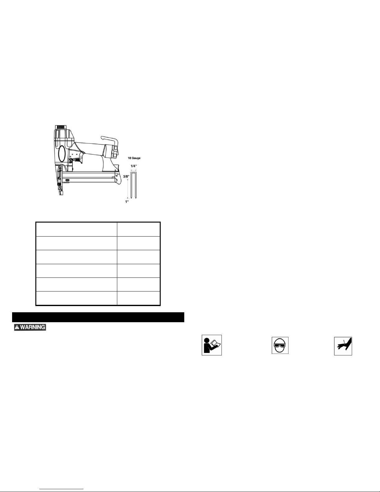
1/4” CROWN STAPLER SPECIFICATIONS
Model Number 8520
Staple Gauge 18 Gauge – ¼” Crown
Air Inlet Size 1/4” NPT
Recommended Operating Pressure Range 70~120 psi
Staple Fastener Length 3/8” ~ 1”
Magazine Capacity Up to 110 pcs
GENERAL SAFETY INSTRUCTIONS
Read and understand all these instructions before attempting to operate your product. Save
these instructions for future reference.
Before using your air stapler: Place a maximum of one drop of air tool oil in the air inlet daily
before use. Over-oiling will cause air leakage. Check and drain any moisture which may be in
the air tank of your compressor. Failure to drain this moisture may damage the interior of the
stapler and cause unit to jam and/or cause air leakage. Before use, please read the instruction
manual completely for safety and maintenance questions.
Never allow the use of oxygen or combustible gas as a power source for the tool. Use
filtered, lubricated, and regulated compressed air only.
Never use gasoline or other flammable liquids to clean the tool. Vapors in the tool may ignite
by a spark and cause the tool to explode.
Do not exceed maximum permissible operating pressure of the tool (120 PSI).
Disconnect the tool from air supply before clearing jams, servicing, adjusting, and during
non-operation.
Do not place your hand or any part of your body in the fastener discharge area of the tool
when connecting or disconnecting the air supply.
Do not keep the trigger pulled on a safety yoke mechanism when carrying or holding the tool.
Never carry the tool by the hose or pull the hose to move the tool. Carry the tool only by the
handle.
At the workplace, always wear the protective equipment such as Z87.1 safety glasses, ear
and head protection.
Do not use a check valve or any other fitting that allows air to remain in the tool.
Never point any operational fastener driving tool at yourself or at any other person.
Read and understand tool labels and manual. Failure to follow warnings could result in
DEATH or SERIOUS injury.
Operators and others in work area MUST wear safety glasses with side shields.
Keep fingers AWAY from trigger when not driving fasteners to avoid accidental firing.
NEVER point tool at yourself or others in work area.
The employer is responsible for ensuring that the manufacturer’s tool operating/safety
instructions are available to operators.
It is the responsibility of the employer and the tool operator to ensure that tools are used
only when the tool operator and all other personnel in the work area ware wearing eye
protection equipment, and when required, other appropriate protection equipment such as
head, hearing and foot protection.
Safety eye and face protection equipment shall conform to the requirements of ANSI Z87.1
The employer and tool operator are responsible for assuring that the tool is kept in safe
working order as described in the Tool Operating/Safety Instructions.
Only qualified personnel shall repair the tool.
The employer is responsible for ensuring that the manufacturer’s tool maintenance
instructions are available to personnel performing maintenance.
Always assume the tool contains fasteners.
Disconnect the tool from the power source when; Unattended, Performing any maintenance
or repair, Clearing a jam, Moving the tool to a new location.
Use only fasteners made or recommended by the tool manufacturer, or fasteners which
perform equivalently to those recommended by the manufacturer.
Refer to the tool maintenance instructions for detailed information on the proper
maintenance of the tool.
Stay alert and use common sense when operating a power tool. If you are tired, under the
influence of alcohol, drugs or medication, do not use the tool as inattention may result in
serious personal injury.
Store tools out of reach of minors and unwanted persons.
Become familiar with the following warning symbols:
Read Manual Wear Eye Protection Personal Injury
3
2
AIR SUPPLY AND CONNECTIONS
The compressed air power source shall be pressure-regulated. The regulated
pressure must not exceed the maximum air pressure marked on the tool. If a
regulator fails, the pressure delivered to the tool must not exceed 1.5 times the
maximum air pressure, or 180 PSI, whichever is greater.
Pressure regulators shall be used to limit the air pressure supplied to the tool.
Regulators shall be set at an operating pressure which is lower than or equal to the
tool manufacturer’s specified maximum air pressure.
Air supply hoses shall have a minimum working pressure rating equal to or greater
than the pressure from the power source if a regulator fails, or 120 PSI, whichever is
greater.
Tools shall be fitted with a fitting or hose coupling on or near the tool in such a manner
that all compressed air in the tool is discharged at the time the fitting or hose coupling
is disconnected.
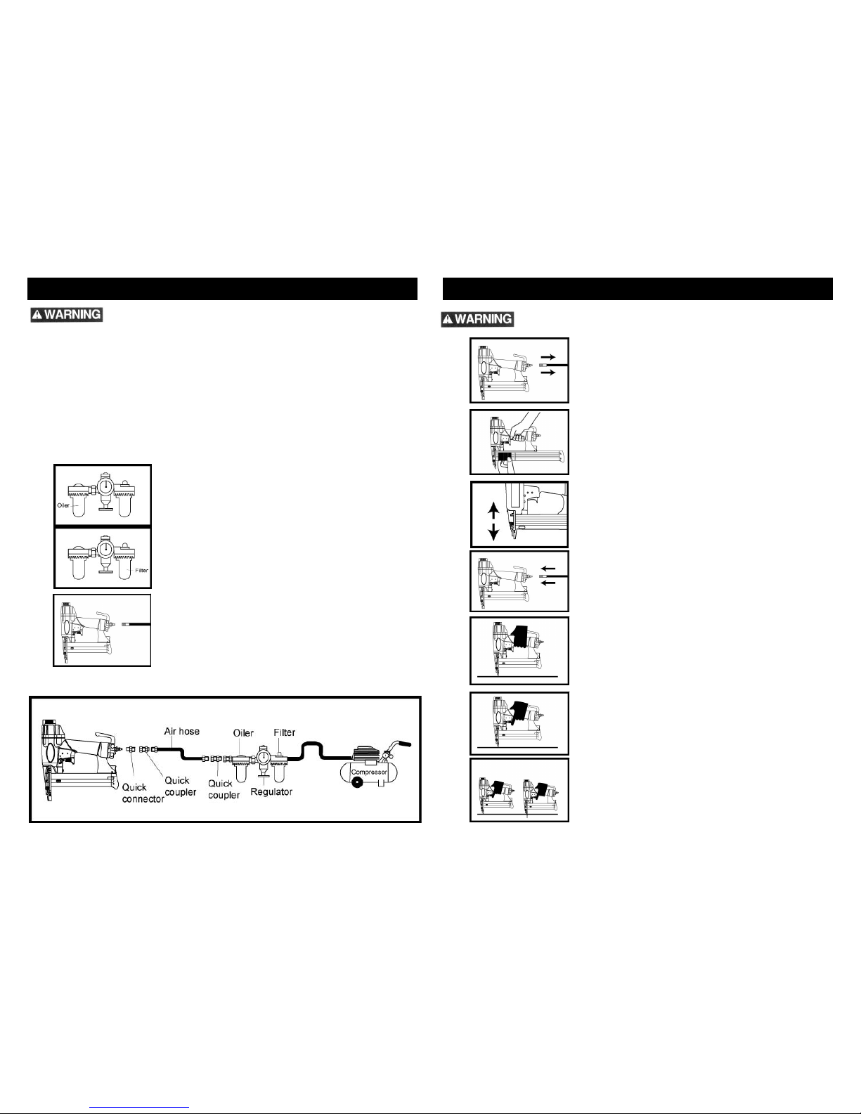
Many air tool users find it convenient to use an
oilier to help provide oil circulation throughout
the tool and to increase the efficiency and useful
life of the tool. Check oil level in the oilier daily.
Many air tool users find it convenient to use a
filter to remove liquids and impurities which can
rust or wear internal parts of the tool. A filter can
also increase the efficiency and usefulness
of the tool. The filter must be checked on a daily
basis, and if necessary, drained.
For better performance, install a 3/8” quick
connector (1/4” NPT threads) with an inside
diameter of .315” on your tool and a 3/8” quick
coupler on the air hose.
The following illustration shows the correct mode of connection to the air supply
system which will increase the efficiency and useful life of the tool.
TESTING THE SAFETY TRIP MECHANISM
Never point any operational fastener driving tool at yourself or at any other
person.
Disconnect the air supply from the tool.
Insert a stick of fasteners into the magazine. See section
on “Loading Fasteners Into Stapler”.
Press down on workpiece and release the contact safety
trip mechanism. Verify there is no binding, sticking or
jamming of this mechanism.
Reconnect the air supply to the tool.
Depress the contact safety trip mechanism against the
workpiece without pulling the trigger. The tool must not
cycle. Never use the tool if a cycle occurs.
Hold the tool clear of the workpiece. The contact safety trip
mechanism should return to its original down position. Pull
the trigger. The tool must not cycle. Do not use the tool if a
cycle occurs.
To complete the testing procedures, depress the contact
safety mechanism against the workpiece and pull the
trigger, the tool must cycle.
4
5
LOADING FASTENERS INTO THE STAPLER
Never point any operational fastener driving tool at
yourself or at any other person.
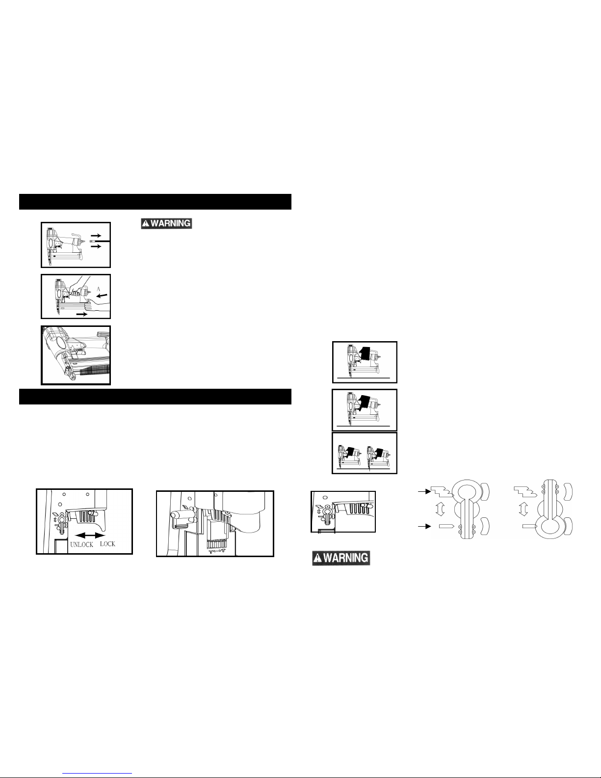
LOADING THE FASTENERS:
1. Disconnect the air hose
2. Depress the magazine latch (A). Pull back on the
magazine cover.
3. Insert a stick of fasteners into the magazine.
Make sure the staples are placed inside the
magazine, with the open end of the staple
pointing down.
4. Push the magazine cover forward until the latch
catches.
FEATURES AND OPERATION
FEATURES
Large capacity magazine with a quick action latch makes loading easy.
The safety lock on the nosepiece must be placed firmly onto the work surface to prevent
accidental firings.
A tapered nosepiece allows greater visibility for precise fastener placement.
A safety switch (Fig. A) that prevents accidental operation of the tool. The switch is located
inside the trigger. To lock the trigger, pull the cover of trigger towards the rear of the unit. To
unlock tool, release (push forward) the cover of trigger. A key lock or tie strip can be place
into the slot for safety storage of unit.
FASTENER DEPTH ADJUSTMENT
The contact trip (Fig. B) may be adjusted up or down to vary the depth of the fastener in the
workpiece. To adjust, rotate the depth adjustment until the desired setting is achieved.
The tool is designed to operate between 70-120 PSI. Lower pressure (below 70 PSI) will
reduce performance of the tool while higher air pressure (over 120 PSI) raises the performance
of the tool beyond its rated capacity and could cause serious damage to the tool and the user.
Most applications will only require the minimum air pressure. However, larger fasteners and
harder woods may require air pressure in the upper range.
TESTING THE CYCLE OF THE TOOL
NOTE: THE AIR SUPPLY SHOULD BE CLEAN AND DRY. FOR BEST RESULTS, DRAIN
THE MOISTURE FROM YOUR COMPRESSOR DAILY. CHECK AND REPLACE ANY
DAMAGED OR WORN COMPONENTS ON THE TOOL. THE SAFETY WARNING LABELS
ON THE TOOL MUST ALSO BE REPLACED IF THEY ARE NOT LEGIBLE. IN CASE THE
AIR TOOL IS UNABLE TO DRIVE THE STAPLE INTO THE WORKPIECE COMPLETELY,
PLEASE ADJUST THE PRESSURE OF THE AIR COMPRESSOR TO AN APPPROPRIATE
PRESSURE.
Depress the contact safety trip mechanism
against the workpiece without pulling the trigger.
The tool must not cycle. Never use the tool if a
cycle occurs.
Hold the tool clear of the workpiece. The contact
safety trip mechanism should return to its original
down position. Pull the trigger. The tool must not
cycle. Do not use the tool if a cycle occurs.
Then depress the contact safety mechanism
against the workpiece and pull the trigger, the tool
must then cycle.
The air tool is equipped with a rotating switch (Fig. C) that can be set to
rapid-fire or single-fire mode.
Fig. C
SINGLE-FIRERAPID-FIRE
Rapid-Fire
Single-Fire
Fig. A Fig. B
6
7
SINGLE-FIRE
When the switch is set to single-fire mode, the tool will not drive a second fastener until the
trigger is fully released and pulled again and the contact trip is pressed against the workpiece.
RAPID-FIRE
Pull the trigger fully and keep it depressed to ensure proper rapid-fire operation.
When the switch is rotated to rapid-fire mode, the tool can drive fasteners continuously. A
fastener will be fired each time the contact trip is pressed against the workpiece, as long as the
trigger is maintained in the pulled position.
OPERATION
Appropriate personal protective equipment is to be worn.
Inspect the tool before operating.
Determine that the tool is in proper working order.
An improperly functioning tool must not be used.
Always assume that the tool contains fasteners.
Do not point the tool toward yourself or anyone whether it contains fasteners or not.
Do not actuate the tool unless the tool is placed firmly against the workpiece.
Respect the tool as a working implement.
No horseplay.
Do not hold or carry the tool with a finger on the trigger
Do not load the tool with fasteners when any one of the operating controls is activated.
Do not remove, tamper with, or otherwise cause the tool operating controls to become
inoperable.
Do not operate a tool if any portion of the tool operating controls is inoperable,
disconnected, altered, or not working properly.
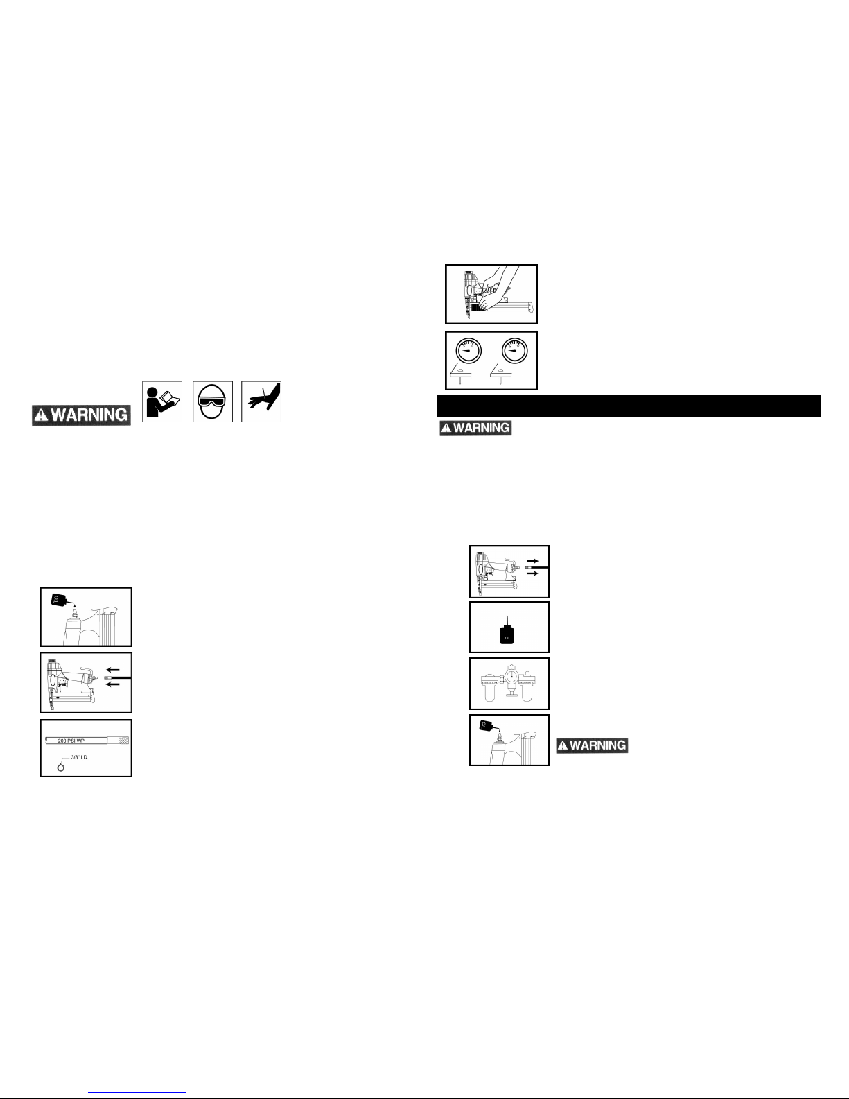
1. Add one drop of the air tool oil into the air inlet.
2. Empty all fasteners from the magazine.
3. Connect the tool to an air compressor using a 3/8” I.D.
hose. Make sure the hose has a rated
working pressure exceeding 200 PSI (13.8 bar).
4. Load the fasteners into your tool following the instructions of
“Loading The Fastener” in this manual.
5. Test for proper fastener penetration by driving staples into a
sample piece of wood. If the fasteners do not achieve the
desired penetration, adjust the air pressure to a higher setting
until the desired penetration is achieved. Do not exceed 120
PSI (8.0 bar) at the tool.
MAINTENANCE
Disconnect the air tool from the air compressor before adjusting, clearing jams,
servicing, relocating and during non-operation.
Only qualified personnel shall repair the tool and shall only use parts or accessories
that are supplied or recommended by the tool manufacturer.
The employer shall ensure that tools which require repair are not further used before
repair. Tags and physical segregation are recommended means of control. OSHA’s
General Industry and Construction regulations require the use of tags.
The employer is responsible for ensuring that the tool maintenance instructions are
available to the appropriate personnel.
The employer is responsible for the proper maintenance of all tools in its possession.
LUBRICATION
Disconnect the air supply from the tool before
lubricating.
Your tool requires lubrication before using it for
the first time, and requires a maximum of one
drop daily before use.
Wipe off excessive oil at the exhaust. Excessive
oil may damage the o-rings of tool. If an in-line
oiler is used, manual lubrication through the air
inlet is not required on a daily basis.
Turn the tool so the inlet is facing up and put one
drop of air tool into the air inlet. Test the tool after
the oil is added.
Never use detergent oil or additives. Use
pneumatic tool oil only.
8
9
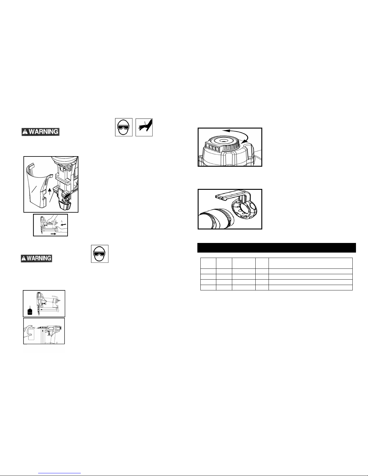
CLEARING A JAM FROM THE TOOL
Disconnect the tool from the air compressor before adjusting, clearing jams, servicing,
relocating & during non-operation.
Fastener Jammed in Discharge Area:
Disconnect tool from air hose.
Before opening the cover plate guard (A), remove
all fasteners from the magazine.
Take off the cover plate guard, and the protective
“no-mar” tip. Then push the quick-release
nosepiece (B) up.
Grab the jammed fastener with pliers to remove.
Fastener Jammed Inside the Magazine:
Disconnect the air tool from air hose.
Depress the magazine latch (A). Pull back on the
magazine.
Remove the jammed fastener by using pliers.
CLEANING THE TOOL
NEVER USE GASOLINE OR OTHER FLAMMABLE LIQUIDS TO CLEAN THE TOOL.
VAPORS IN THE TOOL MAY IGNITE BY A SPARK AND CAUSE THE TOOL TO
EXPLODE AND RESULT IN DEATH OR SERIOUS PERSONAL INJURY.MAKE SURE
TO DRY THE TOOL THOROUGHLY AFTER CLEANING AND BEFORE OPERATING
THE TOOL AGAIN.
1. Disconnect the air supply from the tool.
2. When removing tar buildup from the nosepiece of
the tool, do not allow solvent to get into the
cylinder or damage may occur. After cleaning, dry
off the tool completely.
EXHAUST PORT ADJUSTMENT
The exhaust port may be rotated 360° to direct air
away from operator. To rotate the port, simply turn
left or right the top rotating portion in the desired
direction.
BELT HOOK
The pneumatic stapler includes an integrated belt hook which can be rotated to either side
of the tool.
1. Loosen the two bolts of belt hook assembly.
2. Place the belt hook assembly onto the
rear of tool, and tighten the bolts.
TROUBLESHOOTING
Low
Power
Erratic
Action
Blows Air
Won’t Run
Tool
Noisy
Causes and Solutions
X
Check air pressure.
X X X X
Check for water in lines.
X X
Check power regulator setting.
X X X X
Oil tool with air tool oil.
A
B
10
11
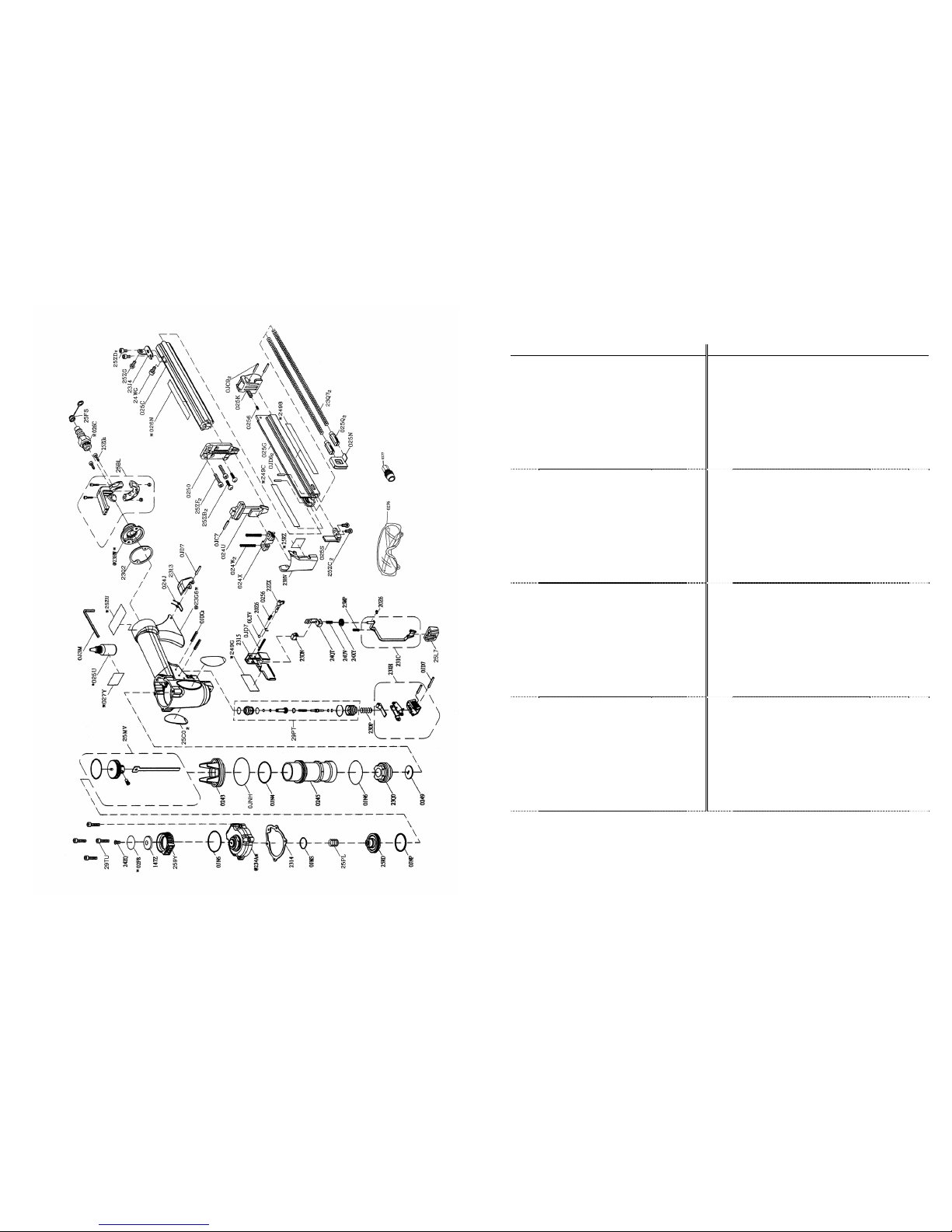
8520 PART LIST
I.D. No. Description Size Qty I.D. No. Description Size Qty
0243 CYLINDER RING #06 1 22ZX ADJUSTMENT LEVER 1
0245 CYLINDER 1 231C SAFETY LEVER ASSEMBLY 1
0249 NOZZLE 1 234A CYLINDER CAP #06 1
0250 GUIDE PLATE 1 23DN GUIDE CLAMP #06 1
0256 COMPRESSION SPRING 2 23DP COMPRESSION SPRING 1
0276 SAFETY GLASSES 1 23G6 BODY #AW 1
0277 FEMALE QUICK CONNECTOR 1 23HV COVER PLATE GUARD #06 1
2313 LATCH 1 23HW REAR COVER #06 1
2314 CAP SEAL 1 23J4 SUPPORT 1
2315 SAFETY LEVER GUARD 1 23Q0 BUMPER 1
2498 LABEL 1 23Q2 END CAP SEAL 1
024J LATCH SPRING 1 23Q7 COMPRESSION SPRING 2
024U FRONT PANEL 1 23XH TRIGGER ASSEMBLY 1
024W COMPRESSION SPRING 2 249C LABEL 1
024X GUIDE CLAMP 1 249G LABEL 1
025C MAGAZINE SEAT 1 24QT ADJUSTING PLATE 1
025G MAGAZINE CAP 1 24UV COMPRESSION SPRING 1
025K STOP PLATE #06 1 24WG HEX. SOC. TRUSS HD. SCREW M4X0.7-7.6 1
025N PUSHER 1 24XY ADJUST WHEEL 1
025Q PUSHER PIN 2 24ZQ HEX. SOC. COUNTERSUNK HD. SCREW M5X0.8-10 1
025S NAILER PLATE 1 259Y GUIDE PLATE 1
025U PNEUMATIC AIR TOOL OIL 1 25BL HOOK ASSEMBLY 1
026C QUICK CONNECTOR 1 25C0 LABEL 2
026N WARNING LABEL 1 25FS QUICK CONNECTOR CAP 1
027Y LABEL 1 25L7 NO-MAR TIP 1
02F8 CAUTION LABEL 1 25MP COMPRESSION SPRING 1
0J3M HEX. WRENCH 3-57 125MV DRIVER ASSEMBLY 1
0JC7 SPRING PIN 2.5-14 125PL COMPRESSION SPRING 1
0JC9 SPRING PIN 3-18 225RD PISTON VALVE HEAD 1
0JD6 SPRING PIN 3.0-12 225RZ WARNING LABEL 1
0JD7 SPRING PIN 3.0-22 325ZB HEX. SOC. TRUSS HD. SCREW M4X0.7-12 2
0JDC SPRING PIN 2.5-22 225ZC HEX. SOC. TRUSS HD. SCREW M4X0.7-8 2
0JMS O-RING P14 125ZD HEX. SOC. HD. CAP BOLT M4X0.7-6 2
0JN4 O-RING 31X2.0 125ZF HEX.SOCKET HD.CAP SCREW M4X0.7-20 2
0JN6 O-RING 30X2.5 225ZG HEX.SOCKET HD.CAP SCREW M4X0.7-12 3
0JNH O-RING 40x2.5 125ZU WARNING LABEL 1
0JNP O-RING 31.8X2.4 129TU HEX.SOCKET HD.CAP SCREW M4X0.7-20 4
0LYV STEEL BALL ψ4 129PT TRIGGER ASS’Y 1
147Z BLOCK #06 1 262C INSTRUCTION MANUAL
1
20Z6 E-RING E-3 22446 CARRY CASE
1
12 13

NOTES
NOTES
15
14
Table of contents
Other Tradesman Power Tools manuals


