Thermolec Acu-Steam PRO Series Instructions for use

Installation Instructions
and Maintenance Manual
for
Acu-Steam PRO Commercial Humidifier
by
Please read this manual carefully before beginning installation.
Feb. 2020 V1.4
!
Pro 7


Page 1
1. Warnings and Disclaimer – Installation Precautions and Recommendations
Please read and understand the warnings and provided instructions fully before you begin this installation and
keep them handy for future reference.
The manufacturer will assume no responsibility and the warranty will be void if the installer or the user does not
adhere to the following precautions/recommendations :
1.1 Water quality and hardness can significantly affect the maintenance frequency of your Acu-Steam PRO
humidifier. If the cold water supply exceeds 180 mg/L, the water is classified as hard and excessive
scaling inside the tank reservoir is possible. If the water supply exceeds 180 mg/L, a water conditioner/
softner is recommended to minimize the maintenance frequency (see section 16.).
1.2 This humidifier will be connected to and used under water pressure and it must be installed in such
a way that if a leak occurs, the water will not cause any damage to the property. Make sure all water
connections are properly installed or a water leak could occur.
1.3 This humidifier is intended for use on ducted forced air systems, which have at least one supply duct
where a positive air pressure can be measured.
1.4 Do not install a humidifier where the surrounding temperature may be 32ºF (0ºC) or colder. Freezing
water will damage the humidifier.
1.5 Do not install a humidifier if the city water pressure exceeds 90 psi. Check the local codes related to
pressure reduction.
1.6 If the supply duct pressure exceeds 2.0” Water Column (0.5 kPa) a drain valve kit (optional)
is required for proper operation.
1.7 The installation, wiring and plumbing of the humidifier must comply with national and local electrical,
plumbing and building codes.
1.8 Electrical wiring and water tubes must not come in contact with sharp edges or hot surfaces.
1.9 Make certain an appropriate drain system is installed and there is no resistance to the flow of the
discharged water.
1.10 Do not set the humidity level higher than that recommended or condensation damage could occur.
1.11 Please beware of sharp edges when you cut into a metal duct.
1.12 Always shut the power off before you start the installation or when doing maintenance. An electric
shock could cause serious injury or death.
1.13 Caution: when you perform maintenance, please be careful because the unit can be extremely hot.
Always allow enough time for the unit to cool down.
1.14 To prevent electric shock or injuries, never operate the humidifier without the covers as there are high
voltage and hot components inside.
1.15 This humidifier will only work with non demineralized water. The maximum water supply temperature is
86 ºF (30 ºC)
Installation must be done by a qualified electrician or HVAC contractor
Page 2
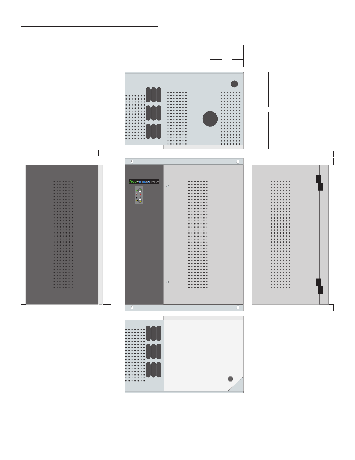
2. Overview and model specifications
!
PRO
23 1/4”
13 1/2”
20”
Ø 3”
Ø 1 1/4”
13”
12 ”
12 5/8 ” 13 1/2”
8”
6”

Page 3
23 1/4”
20”
13.5”
!
A
CU STEAM PRO
Voltage / Phase
kW 208/1 208/3 240/1 240/3 480/3 600/3 lbs/hr kg/hr outlet
4 - - - - 12 5.5 1.5"
6 18 8 1.5"
8 24 10.9 1.5"
10 - 30 14 1.5"
12---- 36 16.5 1.5"
13.5---- 40 19 1.5"
16
Pro12
2.2 - - - - - 6.75 3.1 1.0"Pro7
Pro18
Pro24
Pro30
Pro36
Pro40
Pro50 ---- 50 21.8 1.5"
Steam Output
For other capacities consult factory
Available capacities:
2.1 External view of the humidifier.
14”
13”
11 5/8”
Pro 7
9”
!
Page 4
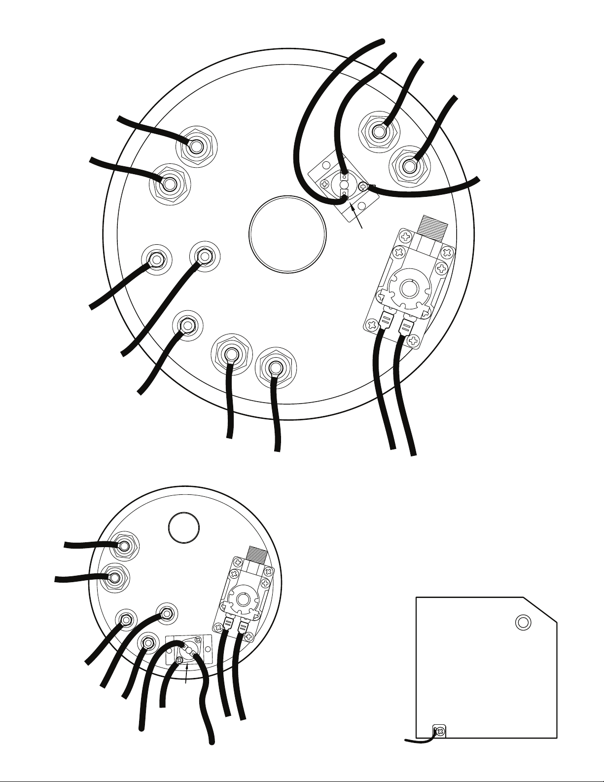
Fig. 2a
Overflow Pan
Pro7
White
Steam Outlet
Black
Black
Black
Black
Black
Black
Heating
Element
Note: depending on
kW, heating element
configuration may be
different.
Heating
Element
Heating
Element
Blue Blue
Electric
Valve
Green
Red
Red
Manual
Thermal
Cut-out
Yellow
White
Brown
Foam
High Level
Low Level
Green
Yellow
Brown
White
Red
Red
Black
Black
Blue Blue
Heating
Element
Electric
Valve
Steam Outlet
High Level
Low Level
Foam
Manual
Thermal
Cut-out

Page 5
3. How to Control the Humidity
3.1 Humidity level and comfort are personal matters but it is generally acknowledged that a Relative
Humidity of 35-45% is desirable. However, you should take the outside temperature into consideration
before setting the humidity level in order to avoid condensation on the windows. Usually, a narrow strip of
condensation around or at the bottom of the window is considered as normal.
3.2 If you installed an Acu-Steam PRO humidistat and an outdoor sensor, this adjustment will be done
automatically through a function called outdoor reset. The outdoor sensor automatically reduces the humidistat
setting according to the outdoor temperature during cold days; it does the opposite during mild days. Please
see Fig. 3b for the percentage of relative humidity on the electronic humidistat label. The digital readout
normally displays the actual humidity and will blink when adjusting the knob to display the setpoint.
3.3 If you are using a humidistat by others, the humidity adjustment according to the outside temperature
might have to be done manually. For your information, the following table shows the recommended setting of
the humidistat according to the outside temperature. Please see Fig. 3a.
.
3.4 No matter which humidification system you are using, please do not forget that the humidity level
cannot adjust quickly. It may take some time to build up the humidity to your comfort level.
3.5 If the space remains unoccupied during the winter season, set the humidistat to the minimum set point
in order to prevent condensation.
Fig. 3b
Outside Temprature Recommended Setting
-22ºF (-30ºC) 15%
-13ºF (-25ºC) 20%
-4ºF (-20ºC) 25%
+5ºF (-15ºC) 30%
+14ºF (-10ºC) 35%
above
23ºF (-5ºC) 40%
Fig. 3a

Page 6
4. Functions of the Electronic Circuit
4.1 The electronic board located inside the unit controls all of the humidifier functions. The front LED panel
is equipped with pilot lights indicating the status of the humidifier. Please see Fig.4a.
Please refer to Article 4.2 for the description of the functions.
The red pilot light, which is a warning light, can either glow all the time or flash when activated.
In case of error, the humidifier enters standby mode. The flashing of the pilot lights indicates which error has
occured. The error recognition sequence is as follows :
•The green pilot light near the power button blinks once;
•The red light flashes a certain number of times, this is the error code;
•A pause with no light at all;
•Another blink of the green light, once;
•Another series of flashing of the red light;
•And so on until the condition is reset or service is performed.
•Shutting the power OFF at the breaker in the main panel or depressing the power button until the
green light is fully on will reset the error code.
4.2 The Acu-Steam PRO humidistat also has two pilot lights to indicate the current status.
The green light is lit when the humidistat is demanding for humidity, thus activating the boiling cycle. The
red light indicates a warning and reproduces the more serious warning codes from the humidifier control
panel when connected with ON/OFF control. If ever the red light is lit or flashing on the humidistat, you know
immediately that the humidifier needs attention.
Display Status Description
On/Standby
Green light OFF The humidifier has no power – Breaker is OFF.
Blinking The humidifier has power, but is in standby mode.
ON The humidifier has power and is functional.
White button Press to put the humidifier in standby mode.
The green light is blinking.
Press and keep depressed 3 seconds to power
or reset the humidifier. The green light is ON.
Fan
White light ON The fan control is activated.
!
On/Standby - Green
Fan
Warning
Steam
Fill
Drain
- White
- Red
- White
- Blue
- Yellow
Fig. 4a
Mode

Page 7
Warning
Red light ON An abnormal condition occurred.
Please refer to the error code table in Section 7.
Steam
White light ON The humidifier is heating water to produce steam.
Filling cycle
Blue light ON The electric water valve is open thus filling the
humidifier.
Draining cycle
Yellow light ON The humidifier is in draining mode.
White button The drain button flushes the tank and empties the water
(a small amount of water will remain in the tank).
!
Legend: SS = stainless steel, FF = furnace fan, SW = supply water, HLS = high level sensor, LLS = low level sensor
Number of
Àashes of
the red light
Error Description Humidi¿er Status Actions to be Taken
by the Technician Reset
OFF No error The humidi¿er is working ¿ne None
Countinuous
ON
The Àood sensor under the
tank senses water in the pan.
Humidi¿er immediately suspends the ongoing
operation. Heating elements and supply valve are
switched off. The power green light is OFF.
Turn power off. Check for leaks around the tank
clamp, SW valve and drain tube. Make sure tank
latches align and gasket is sealing properly.
Automatic Reset when
OverÀow pan dries up.
1Reserved for future use
2Water sensor error Scale formed on sensor. Humidi¿er suspends
operation. Check and clean or replace sensor
Reset when
switching main power
OFF and ON
3
Inadequate water supply
and/or marginal drainage.
The supply valve was open
for more than 6 minutes.
Humidi¿er immediately suspends the ongoing
operation. Heating elements and supply valve are
switched off. The power green light is ON.
Turn power off. Check SW valve circuit for 24V DC
at the valve. Refer to manual (p. 10) and check for
proper drain installation. Make sure SW shut-off
valve is open, SW valve is responding and SW
tube is clear of debris.
Automatic Reset after
5 min or after switching
power off and on.
4
Inadequate drainage. The
tank did not drain or the
draining cycle is too long.
Humidi¿er immediately suspends the ongoing
operation. Heating elements and supply valve are
switched off. The power green light is blinking.
Turn power off. Check for proper drain setup by
referring to manual (p. 10). Check and clean tank,
SS siphon tube and silicon drain tube if necessary.
Reset when
switching main power
OFF and ON
5
The air pressure switch
does not detect enough air
pressure OR the high limit
HSTAT senses extremely
high humidity in the duct.
Humidi¿er immediately suspends the ongoing
operation. The unit goes back to normal operation
as soon as the error condition disappears. The
power green light is ON.
Check if the FF motor is running. If not, turn FF
to continuous operation. Check Àow sensor (pitot
tube) in duct for blockage, then make sure plastic
tube is connected properly from Àow sensor to
PD switch (see manual).
Change furnace ¿lter if needed.
Automatic Reset
when error conditions
disappear
6
Temperature inside the
tank exceeded the high
temperature cut-out setting.
The high temperature cut-out has tripped. The
humidi¿er immediately suspends the ongoing
operation. Heating elements and supply valve are
switched off. The power green light is blinking.
Turn power off. This is a serious condition and will
likely require assistance from a service technician.
Call 1-800-336-9130.
After pushing on the
thermal cut-out button,
automatic reset when
switching main power
ON
7Reduced power capacity Not working at full power capacity. Humidi¿er
suspends operation Check elements and SSRs
Reset when
switching main power
OFF and ON

Page 8
5. Unpacking the Unit
5.1 Contents
Please inspect the carton’s contents and report any missing parts or damage immediately.
1 AcuSteam Pro Humidifier
1 2’ Steam hose
1 Duct mount Highlimit humidistat
1 Installation/maintenance manual
1 Plastic bag containing installation material and hardware
1 Inline water filter (to be changed yearly)
NOTE : The electronic humidistat and the outdoor reset sensor are optional. The humidistat can be either wall
type (RH) or duct type (DH).
Kits and available options (excluding Pro7):
STM508 High pressure drain valve kit (for duct pressure > 2.0” water column, 0.5 kPa)
STM504 inline water filter ( to be changed yearly )
STM507 replacement water level sensors/tune-up kit
STMB501 replacement tank
STM513 O-Ring gasket
STM516 Steam hose (by the foot)

Page 9
6. Installing the Humidifier
Detailed Installation Instructions
This unit is design to be installed on a solid flat surface near the ductwork of a forced air system.
For ease of service, keep a minimum space of 24” in front of the unit.
6.1 Remove both covers by first opening the tank cover and unhook it. Then unscrew the screws holding
the electrical cover and pull it towards you.
6.2 Remove the white wire connected on the water pan at the bottom of the unit. This is the overflow
sensor.
6.3 Remove the overflow pan by sliding towards you.
6.4 The humidifier must be installed on a vertical flat surface.
Please see Fig. 6.a for necessary clearances around the humidifier.
24”
* 12”
* Pro 7 model
12”
* 3”
12”
12”
* 6”
!
A
CU STEAM PRO
Fig. 6a
Page 10
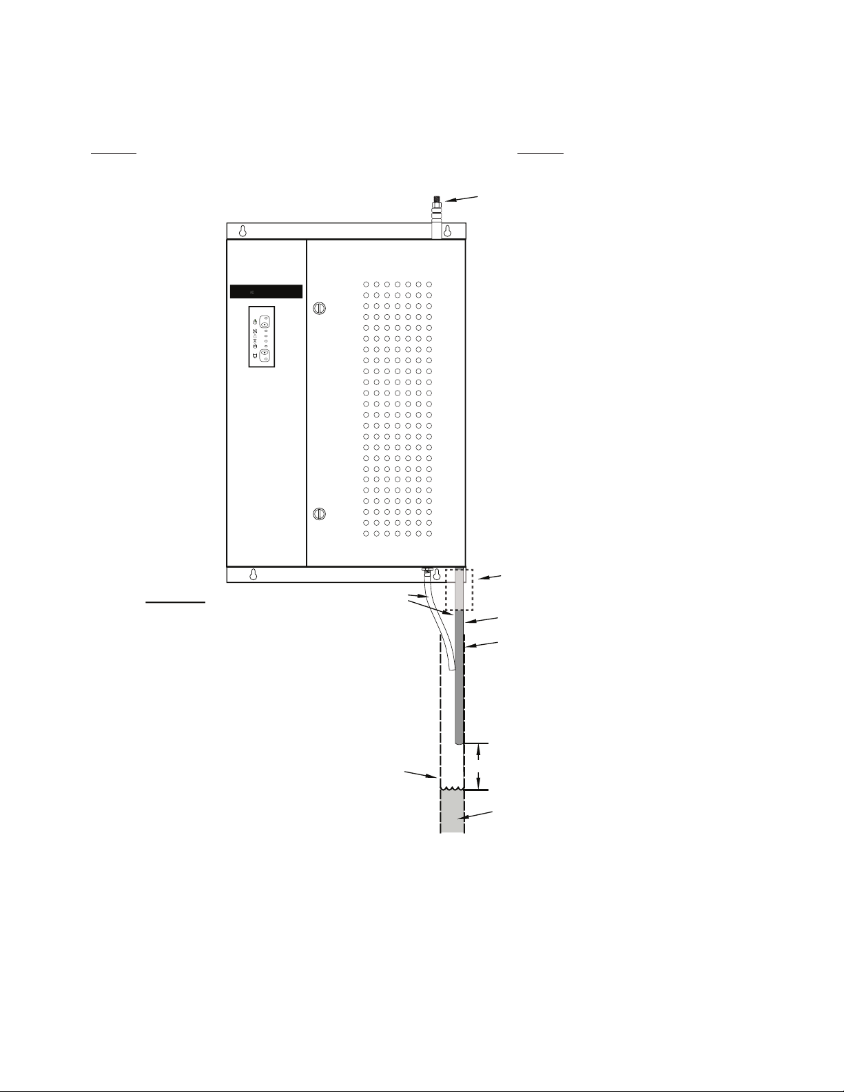
6.5 A rigid drain pipe has to be installed under the unit and connected to the main building drain. We
recommend a standard 1-1/2” ( 1” for Pro7) I.D. ABS plumbing tube to do the installation.
The two flexible tubes (main drain and overflow) coming from the humidifier and which will be inserted in the
rigid pipe, require a minimum free vertical length of 30” (18” for Pro7) below the cabinet. It is very important
to leave an air gap between the rigid pipe and the tubes to allow the siphon to function properly. The flexible
tubes cannot touch any water contained in the drain pipe. Please see Fig. 6b.
6.6 Since the unit is equipped with water level sensors, it is important to install it level from left to right and
from back to front.
6.7 Draw a level horizontal line on the wall and install two screws (# 8 minimum ) from center to center
of the mounting holes to hook the humidifier on the wall, then install two screws at the bottom of the unit and
tighten them partially.
6.8 Level the unit and tighten the four screws firmly.
Water Hammer Absorber
Min. length 30” (18” Pro7)
Drain kit valve (optional)
required for high pressure
installations
Keep this hose straight
Rigid pipe
Min. 1.5” ID
(1” Pro7)
Fig. 6b
For the correct operation of the
siphon, this tube must have a
minimum length of 30” (18” Pro7).
An air gap is mandatory between
the tubes and the rigid drain
A
CU STEAM PRO
!
6” (3” Pro7) Minimum
Water
Warning: These two tubes cannot touch
water in the drain pipe. Keep a minimum
distance of 6” (3” Pro7) between the end
of the tubes and any water in the drain
pipe at all times. Immersing the tubes in
water will interfere with draining and
affect the operation of the unit.
Page 11
7. Installing the Water Supply and drain pan connections
Important Notes :
•Close the main water supply valve before beginning.
•We recommend installing a quarter of a turn shut off valve (not supplied) near the unit. This supply valve (not
supplied) must be attached to a cold water pipe only, easily accessable from the Acu-Steam PRO unit. Since
the unit is draining hot water, cold water is added to reduce the temperature before sending the water to the
drain.
•In case of hard water or water containing particles, we recommend installing a strainer in the water line to
protect the solenoid valve. See section 1.1 for additional information and recommendations concerning water
quality.
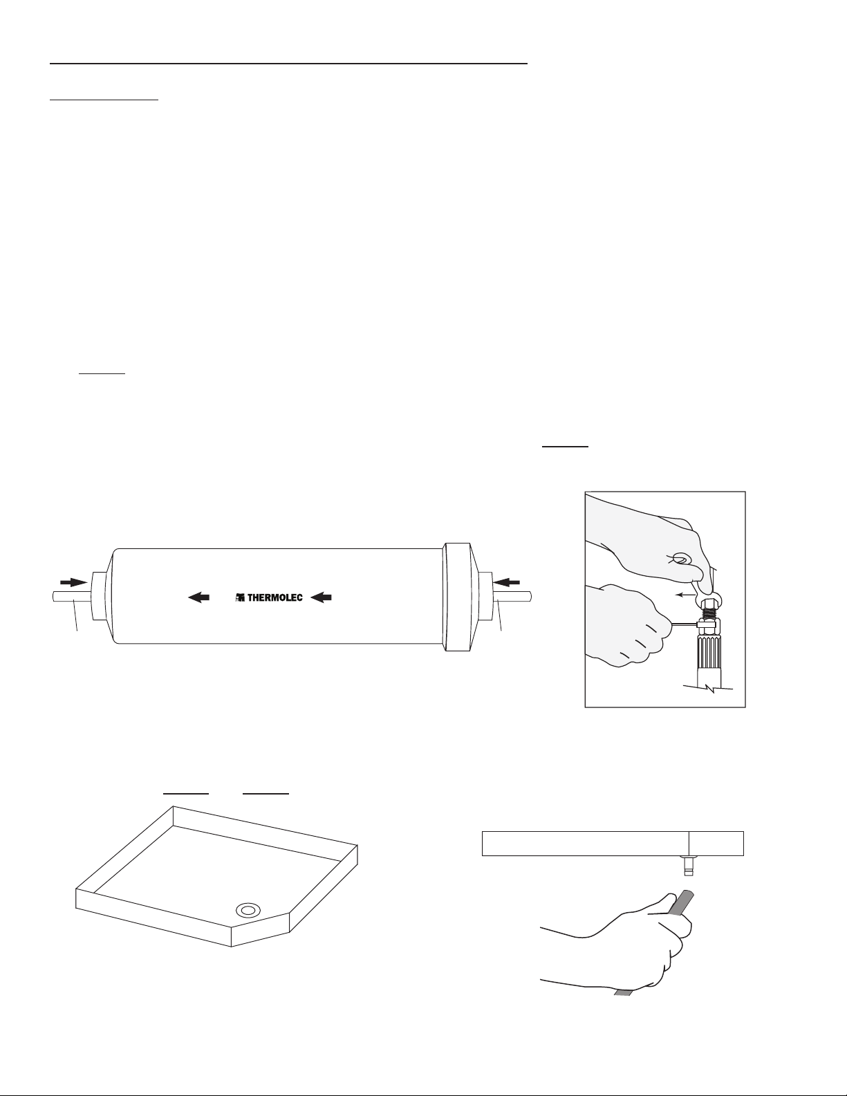
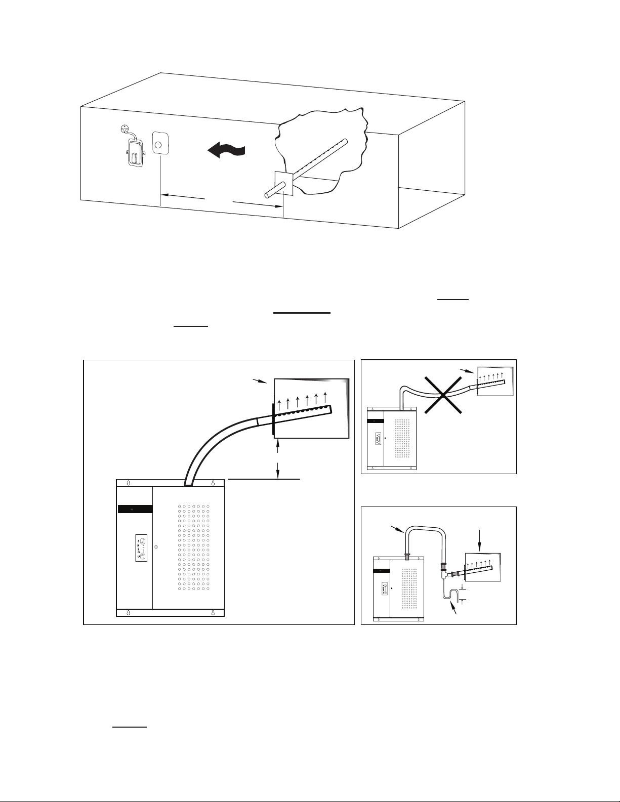
7.1 A water line filter is supplied and should be installed between the shut off valve and the water hammer
absorber. It is strongly recommended to flush the supply water line for 30 seconds before connecting the filter.
Simply push the tubing (plastic or copper) into the quick connect fitting until it bottoms out. Once the filter
is connected it is recommended to flush the supply water through the filter for another 30 seconds (before
connecting to humidifier). We recommend replacing the filter once a year during yearly maintenance. Please
see Fig. 7a.
7.2 At the end of the water hammer absorber, connect the water supply tube, using the same type of fitting
used on the water supply valve. Tighten the compression nut, without stripping, with two wrenches, one to hold
the water hammer end, and one to turn the compression nut. Please see Fig. 7b.
Keep the supply valve closed for now, you will open it during the start-up procedure.
7.3 Take the 5/16 dia. plastic tube and push one end on the connector located at the bottom of the overflow
pan. Please see Fig. 7c and Fig. 7d.
Fig. 7b
Fig. 7c
Fig. 7d
PUSH
1/4” tubing 1/4” tubing
PUSH
FLOW DÉBIT
Fig. 7a
Page 12
7.4 Install the overflow pan under the tank by sliding it in the channel.
7.5 Reconnect the white wire for the overflow sensor on the overflow pan.
7.6 Cut the two drain tubes and insert them in the rigid pipe. Note that the main silicon drain tube must
have a minimum length of 30” to allow the siphon to work properly. It is important to leave an air gap
between the soft tubes and the rigid pipe.
7.7 Open the water supply valve (fully counter-clockwise) to bring water to the humidifier and let the water
pressure enter the system.
7.8 Follow the water supply path completely and carefully check for leaks at the fittings.
8. Installing the Steam Diffuser and the Steam Hose
Steam diffusers must be selected based on steam output and duct configuration. For this reason they are not
supplied with the unit and are sold separately. For improved performance Acu-Steam PRO steam diffuser
tubes are insulated.
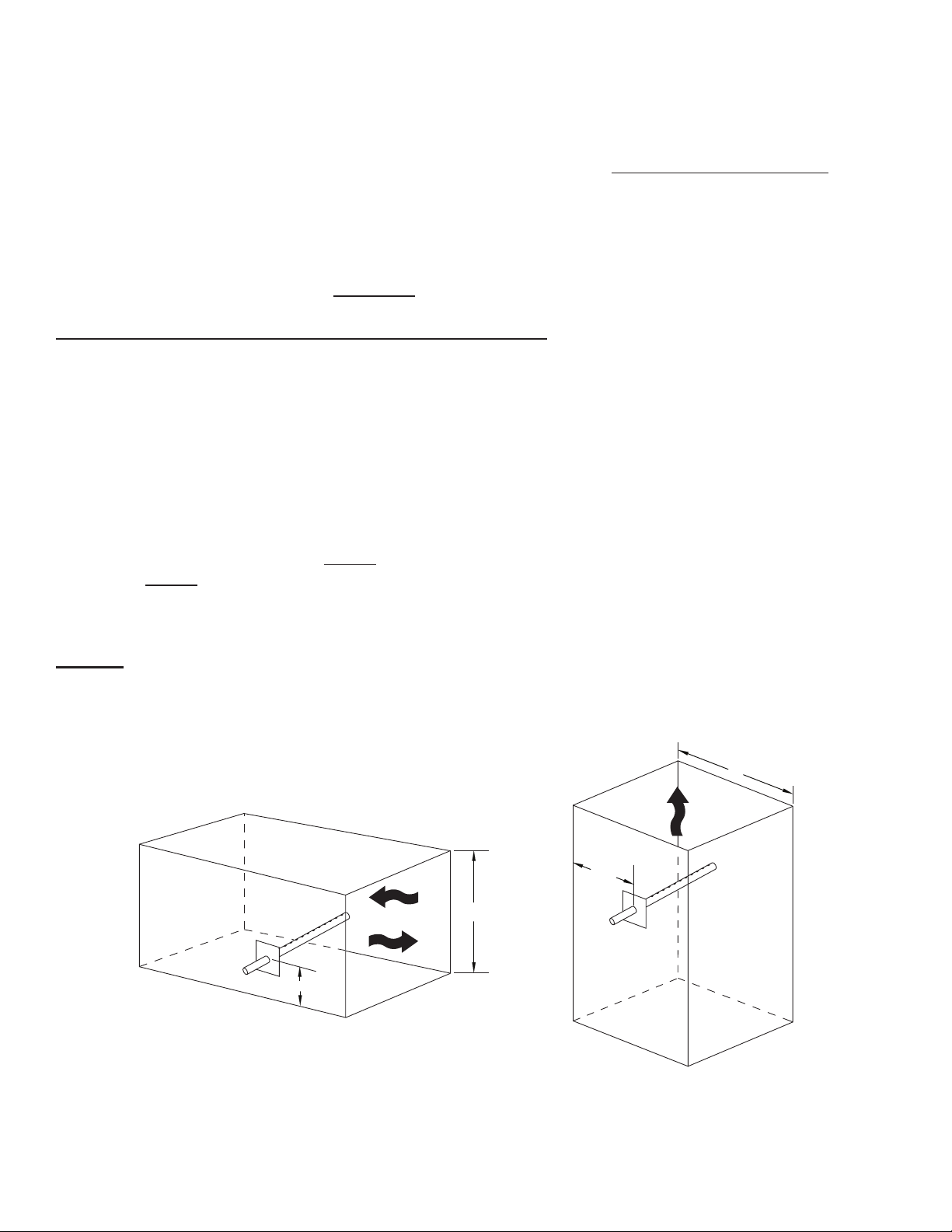
8.1 Proper installation of the diffuser and steam hose is critical for the trouble-free operation of the
humidifier. Please find an accessible location on the duct and make sure you have a minimum length of 60”
of straight duct downstream (without elbows or other obstructions on which the steam could condensate), to
allow the steam to disperse easily into the airflow. Once a suitable location has been found make a 2” middle
insertion hole in the warm air duct for the steam diffuser. For a horizontal duct, make the 2” hole in the lower
third of the duct height. Please see Fig. 8a. For a vertical duct, make the 2” hole in the middle of the duct.
Please see Fig. 8b.
Note: For supply duct pressure exceeding 2.0” Water Column (0.5 kPa) a drain valve kit (optional)
is required for proper operation.
Warning : Before installing anything on a duct, always check that you are not about to cut or drill into an air
conditioning coil or electrical accessories.
Fig. 8a HORIZONTAL DUCT
1/3 H
H
Fig. 8b VERTICAL DUCT
W
Air flow
Air flow
W/2

Page 13
VERTICAL DUCTS:
The diffuser tubes should be rotated either direction for improved steam dispersion or smaller ducts.
HORIZONTAL DUCTS WITH MULTIPLE DIFFUSERS:
Multiple diffusers in horizontal ducts should be installed in a staggered configuration.
IMPORTANT for Pro 7: For horizontal ducts that are only 8” to 10” inch high, install the diffuser at the very
bottom of the duct with only the top two screws and rotate approximately 30º away from the airflow to avoid
condensation forming at the top of the duct.
TOP
AIRFLOW
* Diffuser tubes rotate to fine
tune steam distribution
or
*TOP TOP
AIRFLOW
Fig. 8c
AIRFLOW
Fig. 8d
UP
Air flow
Pro 7 model
Page 14
To avoid excessive humidity in the ductwork a high limit humidistat (included with unit) must be installed.
The high limit humidistat should be installed 5 to 8 feet downstream from the steam difuser follow the wiring
diagram for proper connections.
WARNING : Do not let the hose sag when it is connected to the duct. Please see Fig. 8f.
A sufficient slope with no horizontal section is mandatory to allow any condensation to flow back naturally to
the water tank. Please see Fig. 8g. If condensation water accumulates in the hose, the steam will not be able
to escape normally through the diffuser and will lead to a malfunction of the humidifier. Please keep in mind
that the hose will soften when heated and will have a tendency to sag.
NOTE : If it is not possible to get enough slope for the condensation to return properly to the water tank, then
an S-shaped steam trap (not supplied) must be installed at the lowest point of the steam hose. This steam trap
hose should have a minimum height of 6” (4” for Pro7). For supply duct pressure exceeding 2.0” Water
Column (0.5 kPa) a drain valve kit (optional) is required for proper operation and increase steam trap to
8”. Please see Fig. 8h.
Warm air duct
Warm air duct
Warm air Duct
Steam trap
OKP2TQ
WRONG
Fig. 8f
IDEAL
Fig. 8g
Min. 12”
CORRECT
Fig. 8h
Copper
pipe
Unit must be installed a
minimum of 12” below
the bottom of the duct.
Continuous slope without
sagging is MANDATORY.
Cut hose to the shortest
length possible
!
A
CU STEAM
!
A
CU STEAM
!
A
CU STEAM
Fig. 8e High limit sensor
H
Air flow
5 - 8’
ACE
PDS

Page 15
9 Installing the Air Pressure Probe
9.1 The pressure probe (also called a Pitot tube) connected to the pressure differential switch checks
whether there is enough air pressure in the (warm) air duct to activate the humidifier.
9.2 The probe can be installed in either the warm air or cold air return duct. A 24” long plastic tube is
supplied to connect the pressure probe to the PDS.
9.3 Drill a hole 3/8” dia. in an accessible location in the air duct.
9.4 Insert the probe and fasten it’s base to the duct using two sheet metal screws. The arrow visible on the
probe flange indicates the air flow direction in the duct (i.e. the curved end of the probe has to face the air flow)
Please see Fig. 9a and Fig. 9b.
AIR FLOW
Fig. 9a
#KT2TGUUWTG
Fig. 9b
%QPPGEVVQJKIJRQTV
#KTHNQY
%QPPGEVVQNQYRQTV
HQTVJKUFKTGEVKQPQH HQTVJKUFKTGEVKQPQH
#KTHNQY
6Q2&5YKVEJ
Page 16
10. Making Electrical Connections
NOTE : All internal wiring is done at the factory. All external wiring shall be done by a qualified electrician and
must conform to procedures, regulations and local codes.
10.1 A dedicated breaker in the main panel (or fused disconnect) must be installed.
10.2 Ensure that the wire size and protection equipment conform to the sizes required by the Electrical
Code.
10.3 Wire according to the wiring diagram supplied in the cover of the unit.
10.4 Starting the fan is mandatory with this type of humidifier. The electronic controller board has a control
relay that supplies a dry contact at the terminals marked “F F” to start the furnace fan. The installer must
use this contact to engage a relay that starts the furnace fan motor when required. Please refer to the furnace
instruction manual to find the right wiring diagram. The standard rating of these contacts is 3A @ 240VAC or
6A @ 120VAC. Please do not exceed these ratings.
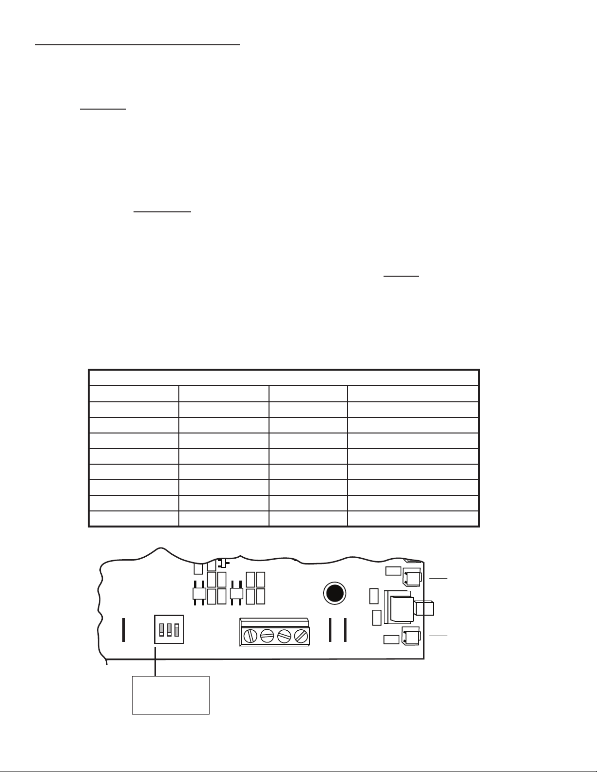
10.5 The DIP switches, located on the bottom of the circuit board (see Fig 10a), are set by the factory based
on the kW of the elements used in the unit.
NOTE: Changing the DIP switches will affect the function of the unit and may cause undesirable results with
improper settings.
Switch numbers on DIP-switch (THF1905 firmware)
1 2 3 POWER (KW)
ON ON ON 4 / 1 PH
OFF ON ON 6 / 1PH
OFF ON ON 6 / 3PH
OFF OFF ON 8 / 1PH
ON ON OFF 10 / 1PH & PRO7
OFF ON OFF 12 / 3PH
ON OFF OFF 13.5 / 3PH
OFF OFF OFF 15.5 / 3PH
Fig 10a
&+2UYKVEJ
G HSTAT
24VFLD
M1
M2
M3
M4
M5
M6
A A
Steam LED
Fill LED
Drain LED
ON
1 2 3 OFF
ON

Page 17
11. Installing and Connecting to a Humidistat
11.1 See wiring diagrams in section 19 for proper connection. When using an Acu-Steam electronic
humidistat with outdoor sensor please refer to the instructions included with the humidistat (see page 5,
sections 3.1 through 3.5 explain the functions of the Acu-Steam wall and duct humidistats). If you decide to use
a standard mechanical humidistat by others, connect the mechanical humidistat between the terminals marked
GND (ground) & HSTAT ON/OFF on the humidifier electronic board.

Page 18
NOTE:
The Acu-Steam PRO board has a memory that remembers the last sequence of operation when the power is
turned off, hence the unit might start at step 2 or 3 when you put the power back on. Also, timings may slightly
vary depending on the capacity of the unit, the pressure of the water inlet and the quality of the water.
12 Working Principle :
12.1 Acu-Steam PRO produces humidity from steam dispersed directly into the supply duct.
12.2 A humidistat (installed either on the wall or the air return duct) controls the unit. You set the knob of the
humidistat according to your desired level of humidity (35-45% recommended). Please read section 3 about
the Acu-Steam humidity control.
12.3 When the humidistat senses a need for humidity, it starts the humidification process.
12.4 The tank fills with water.
12.5 The electronic control starts the blower fan to move the air as the humidifier starts boiling water and
producing steam. If the fan cannot start (i.e. there is no air movement to transport the steam or insufficient air
pressure), the humidifier stops itself. Please note that it may take a few minutes to bring the water to a boil.
The steam exits the water tank through the steam hose, moves through the steam diffuser installed in the
warm air duct and is released into the duct where it mixes with the moving air.
12.6 As water evaporates, the electric valve opens as needed to replenish the water in the tank.
12.7 When the humidity reaches the desired level, the humidifier stops producing steam. In order to remove
scale and keep the tank as clean as possible, the humidifier drains after a certain number of steam producing
cycles or when it detects foam conditions. If there is still a demand from the humidistat after draining, the tank
refills and starts to produce steam again. This process is part of the self-cleaning feature.
12.8 When the humidistat is satisfied, the fan continues to run for a short period of time in order to eliminate
the steam from the ducts and the unit goes to ready mode, waiting for the next call from the humidistat.
This manual suits for next models
8
Table of contents
Other Thermolec Humidifier manuals


