Thermomax SMX 100 User manual

THERMOMAX
SMX 100
MicroprocessorBasedRefrigerationController
DataloggerandAlarm
ENGLISH
www.Thermomax-Group.com

CONTENTS
SECTION 1 - INTRODUCTION ...................................................…...................... 2
SECTION 2 - INSTALLATION ..................................................….…...................... 3
2.1 - SMX100Unit ....................................................................... 4
2.2 - Sensors .........................................................……............... 4
2.3 - AlarmRelay ..................................................…….…............ 5
2.4 - Power Connections and Wiring Diagram ……..........…. 5
2.5 - Battery ............................................................………........... 6
SECTION 3 - SMX100OPERATION ...........................................……............…. 7
3.1 - DESCRIPTION ......................................…...……...........… 7
3.2 - MAIN SCREEN:
3.2.1 MainInformation Displays ............…….........…... 9
3.3 - SET SCREENS:
3.3.1 SET SCREEN 1: Clock / Calendar ..........………..10
3.3.2 SET SCREEN 2: System Pre-sets 1 .......……..... 11
3.3.3 SET SCREEN 3: System Pre-sets 2 ........…….... 13
3.4 - DEFROST SCREENS: Real-time Defrost Settings 14
3.5 - ALARM/DIAGNOSTIC SCREENS:
3.5.1 ALARM SCREEN: High and Low Level Alarm
Pre-set ....................................................................... 16
3.5.2 DIAGNOSTICSSCREEN: System Status
Information …......... 18
3.5.3 DATABANKDIAGNOSTICSSCREEN ..…....19
3.6 - PLOT SCREENS:
3.6.1 PLOT SCREEN 1: Current Day Plot .…... 20
3.6.2 PLOT HISTORY: Data Log of Previous
Days ......................................... 21
3.7 - CALIBRATIONTRIMMING ................................................. 22
3.8 - DATATRANSFER .................................................... 23
3.8.1 Transferring Data Using the Masterlink
Software .................................................................. 23
3.8.2 Transferring Data to the Masterlink Hardware .. 23
3.8.3 Printing Data to the Thermomax Serial Printer .. 25
3.9 - DATATRANSFER - PanelmountunitsOnly .................... 26
SECTION 4 - FAULTFINDING ...................................................................…….... 30
SECTION 5 - SPECIFICATIONS ..........................................................……......… 31
KEYPADLOCK …………………………………………………......……………… 32
NEWFEATURE OF SMX100 PANELMOUNT …………………….........………. 33
1

2
SECTION 1 - INTRODUCTION
The SMX 100 microprocessor-based system uses modern technology to ensure that
the cold-room is controlled and monitored with the greatest of ease.
The large graphics LCD display communicates the information to the user with
clarity, making programming and setting up friendly and uncomplicated, without
compromising its sophistication and digital accuracy.
The datalogger uses the novel approach of a paperless logging and filing system,
which allows the data of any day in its history to be read and examined with a few
presses.
SUMMARY OF FEATURES
CONTROLLER
•Bargraph display of cold-room and product temperature with rise / fall
indication.
•Large, clear display of room, product and evaporator temperature.
•Cold-room thermostat adjustable in 1°C steps with adjustable differential.
•Compressor switching limiter for short-cycling prevention.
•Fan enable thermostat.
•12 Cycles of real-time defrost with adjustable duration, termination
temperature and dwell period.
•Manual defrost activation and override.
ALARM
•2-Stage high and low level alarms with mute and reset facilities.
•Stage 1 temperature threshold with trigger delay.
•Stage 2 limit temperature with immediate trigger.
•Status window for system fault indication.
•Diagnostics screen revealing system parameters.
•Alarm history record for low alarm, high alarm and mains fail.
•Battery back-up for mains-fail operation.
DATALOGGER
•Paperless datalogger with automatic filing by date.
•50-year clock / calendar for datalogger filing.
•The PRODUCT temperature is sampled every 15 minutes and stored to
an internal databank.
•Defrost and alarm state sampled every 15 minutes.
•Contents of internal databank can be transferred directly to the PC or via a
MASTERLINK HARDWARE module.
•‘Percentage of internal databank used’ indication in bargraph and digital form.
Note: The information supplied in this manual is for guidance only - no part of this
may be used for any agreement, whether express or implied, or to form any contract.
Thermomax reserves the right to change specifications without prior notice.

SECTION 2 – INSTALLATION
NOTE: This installation procedure is for guidance only, and its suitability should be
verified by the installer.
It is assumed that the refrigeration plant is physically installed and tested, and is
ready for operation and connection to the electric supply.
SAFETY PRECAUTIONS
The following safety precautions are strongly recommended:
1Before attempting to install and operate the unit, read this instruction manual
carefully.
2Installation and any maintenance required should only be carried out by
suitably qualified personnel.
3It is recommended that the unit be connected to the mains supply via a
suitably rated isolating switch.
4WARNING: When the unit is connected to the mains supply and the cover is
opened, circuits at mains voltage will be exposed. Therefore when installing
the unit ensure all required connections (including battery connection, if
included), are made and covers replaced before turning on the mains supply.
Ensure that all connections made are secure. If any maintenance work e.g.
installing a new battery is required, ensure that the unit is isolated from the
mains supply before removing the cover. Never leave the unit unattended if
the cover has been removed and the mains supply is connected.
5Do not exceed unit ratings as shown on the ratings labels.
6It is advisable to route mains cables away from low voltage or sensor cables.
3
4
2.1 SMX 100 UNIT
NOTE: For viewing comfort, the SMX 100 should be positioned at eye level.
It is always good practice to keep electronic controls away from extremes of
cold, heat and electrical plant, as extremes of temperature may reduce the
lifetime of the device, and heavy electrical loads, switches, relays or
contractors too close to the device may cause electrical and electro-magnetic
interference when switched on or off.
2.1.1 Knock out the entries into the moulding, either behind or under the
box, whichever is suitable for your particular installation.
2.1.2 Fasten the screw corresponding to the top centre lug on the back of
the SMX 100 unit, into the wall or panel on which the control box is to be
mounted. Leave a gap of approximately 3mm between the screw head and
the wall. Position the unit and slot in the lug over the screw.
2.1.3 Level the SMX 100 unit and, if using rear entry, mark the entry holes
in the panel behind the appropriate knockout entries, as well as the two lower
mounting holes. Remove the unit, drill the necessary holes in the panel,
assemble any grommets or conduit adapters if used, replace the box and
fasten using the two lower screws.
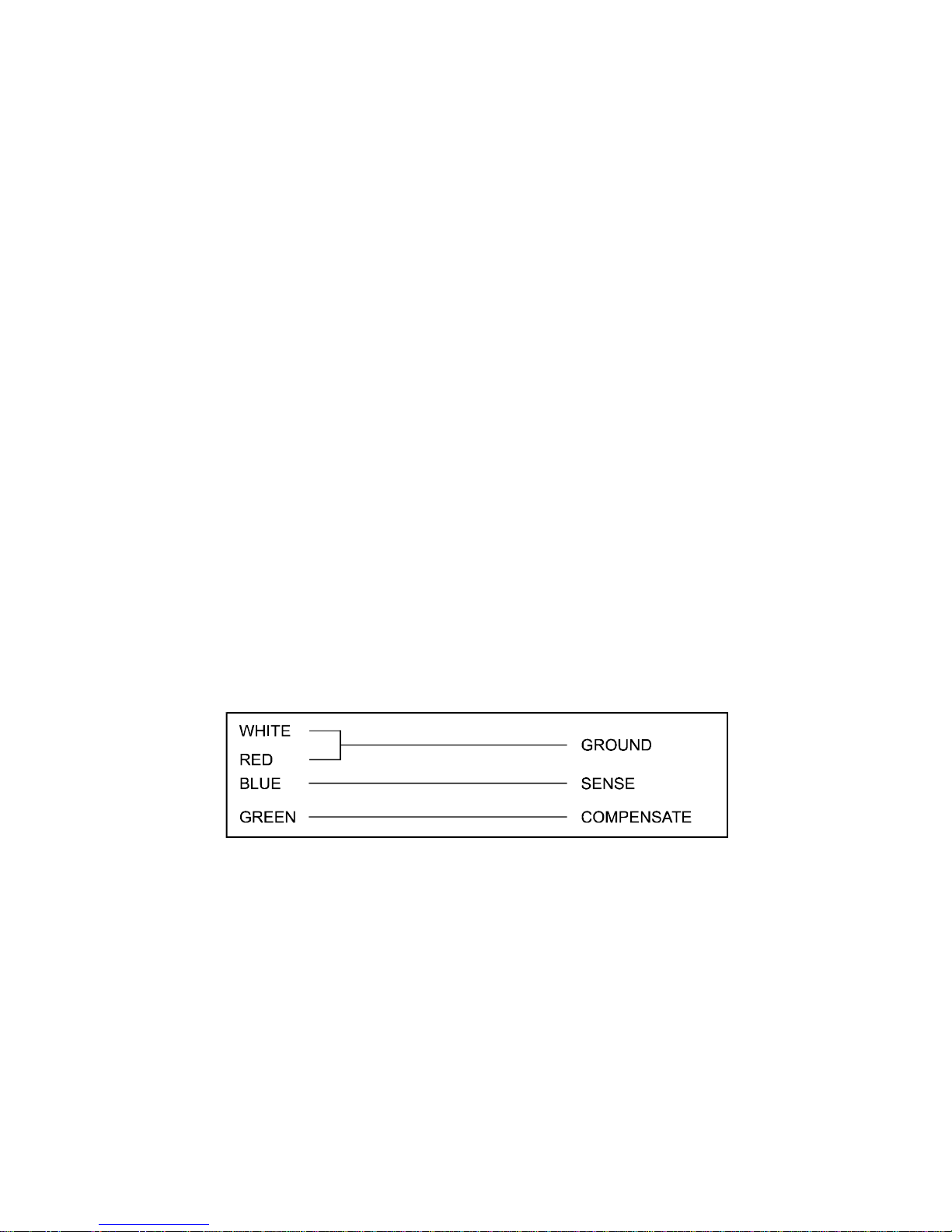
2.2 SENSORS
Included are three identical temperature sensors, each supplied with 5m of
cable. If required, sensors are available with extended cable lengths or
alternatively, sensor extenders are available, also in a variety of lengths. If the
sensors need to be extended but factory-made extenders are not available,
they can be extended using a suitable 4 core or 3-core cable, according to
the diagram shown below.
As with all PT100 sensor applications, a good connection is vital. It is
therefore recommended that wherever there is any doubt, a factory-extended
sensor or a sensor extender should be used.
2.2.1 Install the ROOM sensor in the cold-room, ensuring that it is not too
close to either the evaporator fan or the door. Position the sensor such that it
reads the average cold-room temperature.
2.2.2 Attach the EVAP sensor to the evaporator fins, ensuring that it is not
too close to the defrost heater elements. Ideally, the sensor should measure
the temperature of the evaporator coil, and should not be directly affected by
the heater element. Therefore it is important to ensure good heat conduction
between the evaporator tube and the sensor.
5
2.2.3 Install the product sensor either to measure the air temperature or
product temperature (or simulated product), as required, depending on the
application. The SMX 100 uses the temperature measured by this sensor for
logging purposes only.
2.3 ALARMRELAY
NOTE: The alarm relay is a 3 contact changeover arrangement which is
isolated (volt-free). This relay is normally energised, and switches off when
the alarm is triggered, or in case of mains failure. It may be used to trigger
an external bell, warning lamp, or digital communicator (telephone dialler).
Low Voltage only should be applied to the alarm relay terminals.
If an external device is used, connect the alarm relay as appropriate.
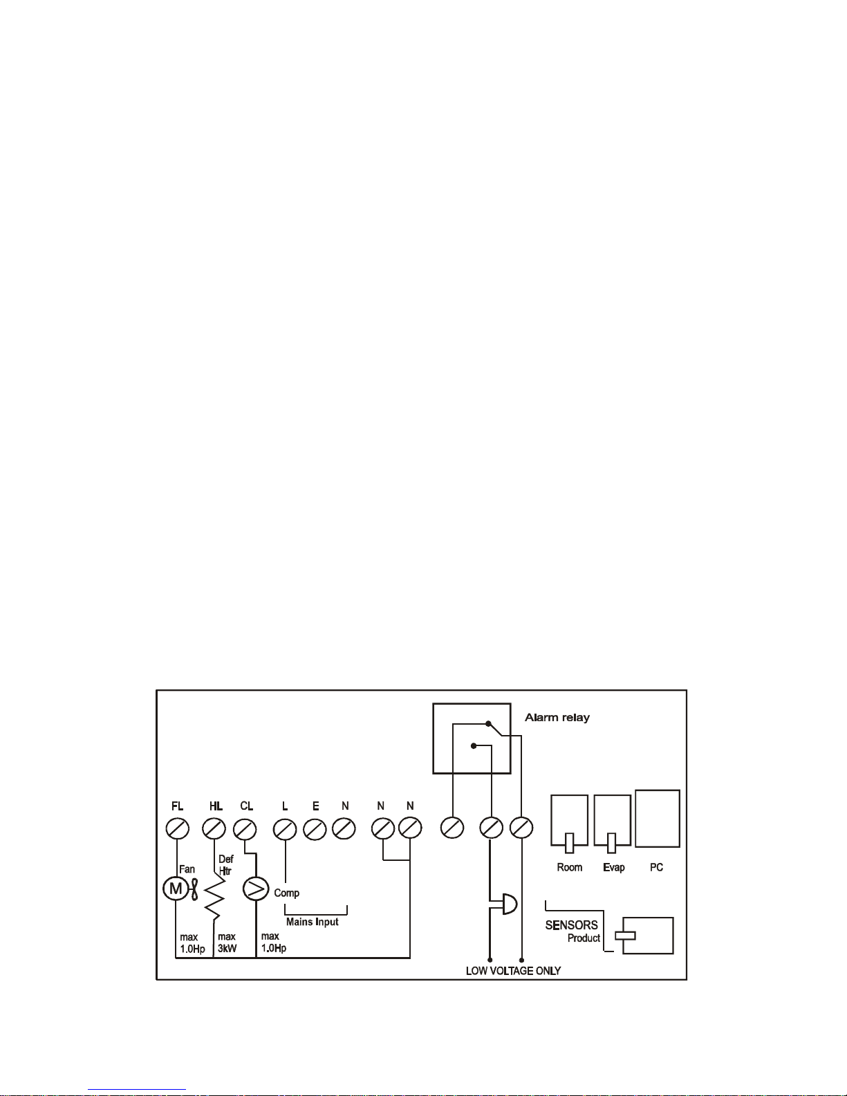
2.4 POWERCONNECTIONSANDWIRINGDIAGRAM
NOTE: This device should be properly earthed. Flexible wires simplify
connection to the terminals. All connections should be secure and
adequately tightened, though not over-tightened, as loose power connections
will over-heat, and may cause fire. It is important that the specified loads of
13A per output are not exceeded. Where these loads may be exceeded,
external contactors should be used. It is good practice to keep mains cables
away from sensor cables and other low voltage signal cables.
2.4.1 Connect the compressor, fan and defrost heater cables to the
corresponding terminals in the SMX 100 unit, referring to the diagram below.
2 4.2 Connect the mains wires.
The unit is now ready to be powered up.
THESE RELAY RATINGS APPLY TO THE
STANDARD UNIT ONLY

6
2.5 BATTERY
The battery supplied is a PP3 nickel metal hydride rechargable battery and is
attached to the lid of the terminal compartment, but not plugged in. This
should be plugged in after installation. This battery is not essential for the
system operation, but is used in the case of power failure, thereby continuing
to log the product temperature for up to 1 hour, and maintaining the system
clock. If a longer period of mains failure is anticipated, a battery kit of up to
72 hours capacity can be supplied by Thermomax.
If the power cut takes longer and the battery has discharged, the clock must
be reset when the power supply is re-established. The system parameters
remain intact.
It is recommended that this battery be changed every 12 months, in order to
maintain good mains failure operation. When replacing, ensure that the
same type of battery is used as specified - only a rechargeable PP3 battery
should be used directly, as the battery is charged from the unit.

7
SECTION 3 - SMX 100 OPERATION
In order to fully understand the operation of the SMX 100, this section should be
read carefully.
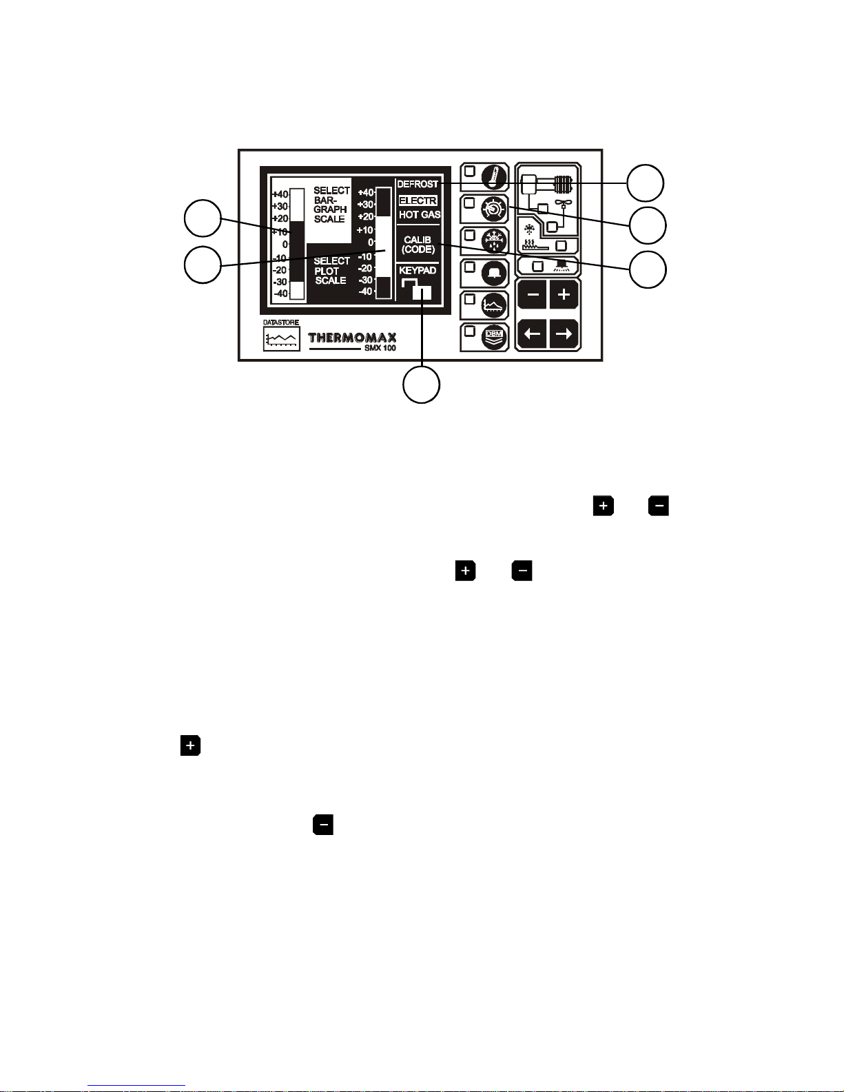
3.1 - DESCRIPTION
1GRAPHICS LCD DISPLAY
Displays all the information. The contrast is adjustable to suit the user.
(See 3.2.1 Main Screen 1).
2FUNCTION KEYS
There are six function keys on the SMX 100 datalogger:
- Alarm Screen
- Main Screen - Diagnostics Screen
- Databank Diagnostics Screen
- Set Screen 1
- Set Screen 2 - Plot Screen
- Set Screen 3
- Defrost Screen 1 - Data Transfer Key
- Defrost Screen 2
3SELECTKEYS
Within each function, there are some parameters that can be selected for
setting or displaying purposes. The keys allow the required
parameter to be chosen, without changing any of its properties.
1
3
4
5
2
8
4SET KEYS
The and keys are used to set the value of any selected parameter, by
increasing and decreasing the value respectively.
In most of the functions, described later in the manual, the and keys
have an auto-repeat facility: press and hold the key in order to advance
quickly.
Note: The and keys are the only keys which can alter the value of a
selected parameter. Other keys may be pressed to view or select these
parameters without effecting any change in the system.
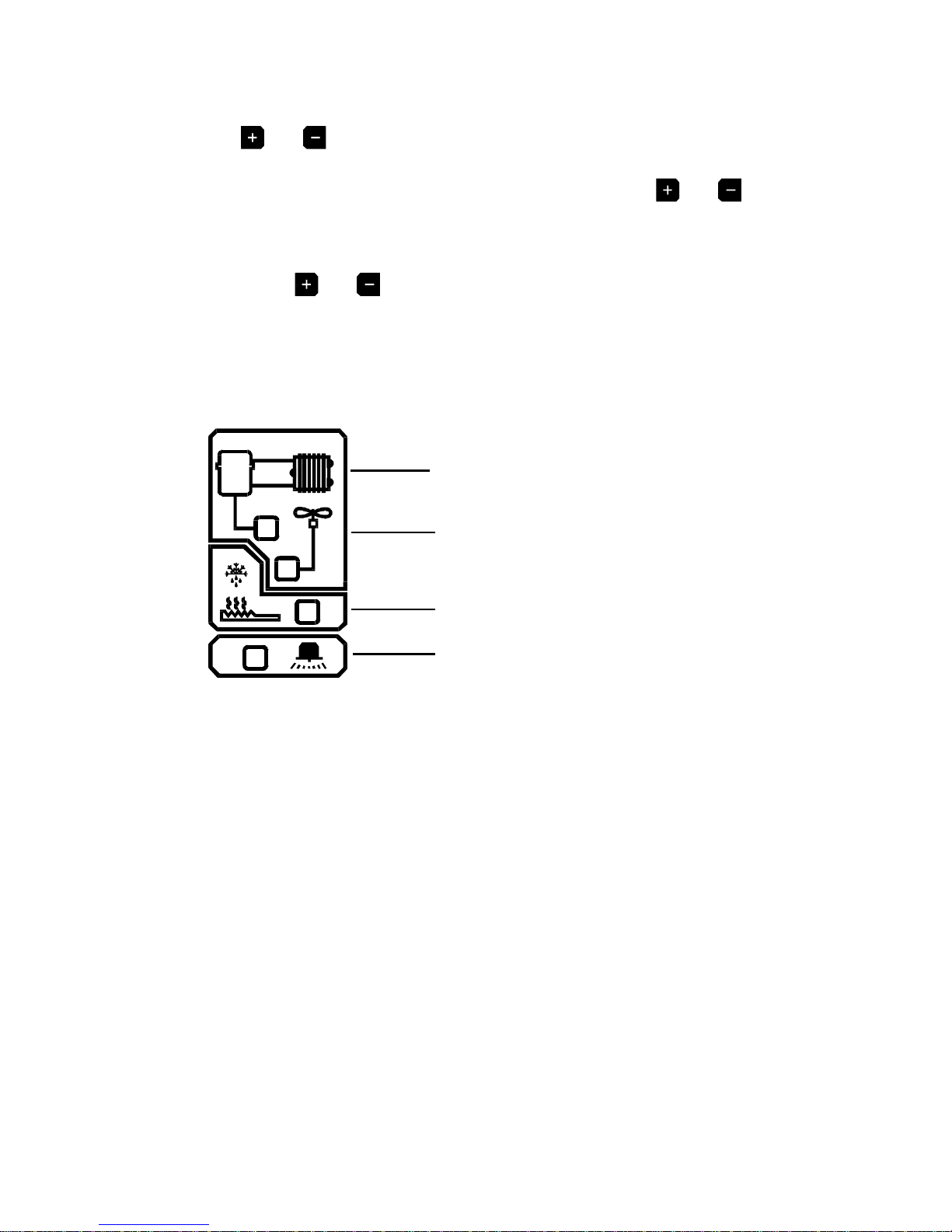
5INDICATORS
The indicators represent the state of the output relay. When lit, they indicate
that the corresponding relay is energised.
COMPRESSOR
FAN
DEFROST HEATER
SYSTEM ALARM

9
3.2 MAINSCREEN
3.2.1 MAIN INFORMATION DISPLAYS
1MAIN function selector.
2Clock display: 24-hour format with day of week abbreviation.
3Cold-room temperature bargraph display.
4Product temperature bargraph display.
5Display select indicator.
The highlighted box indicates which temperature is displayed.
The options are : E - Evaporator
R - Room (cold-room)
P - Product (temperature used for logging purposes
only)
To change selection, use the keys, as appropriate.
Note: The evaporator temperature view is momentary only. The display will
revert back to room temperature when the select key is released.
6Digital display of selected temperature, with minimum/maximum indication.
The minimum and maximum values are daily values, and are reset at
midnight every day.
7Internal databank indicator: This indicates the percentage ‘used’, in both
bargraph and digital form.
Note: The display contrast may be adjusted from this screen by pressing
the key to increase or the key to decrease the contrast.
To adjust quickly, press and hold the required key for auto repeat.
3
2
7
6
1
4
5

10
3.3 SETSCREENS
3.3.1 SET SCREEN 1: CLOCK / CALENDAR SCREEN
1SET SCREEN function selector
The datalogging system uses the calendar to file the logged data.
2Selection indicator
The highlighted parameter is adjusted by pressing the or key..
(The selections are: ‘year’, ‘month’, ‘day’(↑), ‘hour’ and ‘minutes’.)
The ↑indicates that the day on the calendar above is being set.
The clock is in 24-hour format.
To advance quickly, press and hold the or key for auto repeat.
3Calendar
This is the calendar of the month selected, with day of the week indication.
SETTINGTHE DATEANDTIME:
Step 1: Use the keys to set the current ‘Year’.
Step 2: Use the key to move to the ‘Month’ option and then use the
keys to set the current month.
Step 3: Repeat step 2 to set the current ‘date’ and ‘time’ (‘minutes’
and ‘hours’) in turn.
1
3
2

11
3.3.2 SETSCREEN2:SYSTEMPRESETS1
1SET function Selector
Pressing this key a second time reveals Set Screen 2; the pre-sets for
viewing or adjustment.
2Cold-room temperature set point (-50°C to +50°C)
This is the thermostat temperature indicating the required cold-room
temperature. To set or adjust this parameter ensure that the keypad lock is off
(Ref. 3.3.3) and press the or key as required.
3Cold-room Thermostat Differential (0°C to 10°C)
Pressing the select key will highlight this pre-set.
This is the differential (hysteresis) of the thermostat.
Note that if a differential of 2°C is selected, assuming a cold-room
temperature of –8°C, the temperature has to rise to –6°C before the
compressor will switch on, and then drop to -10°C before the compressor will
switch off.
The coldroom temperature deviation in this case will be –10°C to –6°C, i.e.
4°C.
In general, the temperature deviation allowed by the system will always be
twice the selected differential.
In real life, the true temperature deviation will usually be more than the
above, due to the delay in the response of the plant.
4Switch Delay (0 - 99 min.)
This is a time delay to prevent the compressor from short-cycling. Each time
the compressor is switched on, the timer is triggered. The compressor will
subsequently not be allowed to switch on until the delay has expired.
3
5
6
10
1
9
8
7
2 4

12
5‘Fan Run’ Mode
Press and hold the key for 3 seconds to select this mode. In this mode,
the fan will run when the unit is not in a defrost cycle and when the
evaporator has reached the ‘FAN ENABLE’ temperature - (normal mode).
6‘Fan Stop’ Mode
Press and hold the key for 3 seconds to select this mode. In this mode,
the fan will stop one second after the compressor switches off during a
refrigeration cycle. Point 7 describes the Fan Operation after a defrost cycle.
7Fan Stop Delay (1 to 99 minutes) – FAN STOP Mode Only
This feature concerns users who utilise the “FAN STOP” mode of operation.
When a defrost cycle terminates in “FAN STOP” mode, the fan will switch on
only after the compressor switches on and this FAN DELAY period has
expired.
8Fan Enable Temperature (-50°C to +50°C)
This is a thermostat, which disables fan operation any time the evaporator
temperature exceeds this pre-set value. Its main use is to prevent warm air
from being transferred into the cold-room immediately after a defrost cycle.
The fan thermostat has a built-in differential of +/-1°C, i.e. when the pre-set
temperature is 0°C, the fan will switch on when the evaporator drops to –1°C,
and will switch off when it rises to +1°C.
9Manual Defrost
This facility allows the user to perform the following functions:-
(i) Defrost Cycle Initiation lasting 1 - 99 minutes.
When the system is in a refrigeration cycle, this display will show 0 min. In
order to manually force the system into a defrost cycle, simply ‘add’ minutes
of defrost by pressing the key. The system will immediately enter into a
defrost cycle, and the display here will show the duration of defrost still
pending, automatically decreasing each minute.
Note : If the evaporator temperature rises above the defrost termination
temperature 1, the defrost cycle will terminate.
(ii) Defrost Cycle Adjust : During a defrost cycle, the defrost duration
remaining will be shown on this display.
This duration may be adjusted or set to ‘0’ to terminate defrost.
10 Language Selection
The language used by the system to communicate the information may be
selected here. Press or keys to select the required language.
13
3.3.3 SETSCREEN3:SYSTEMPRESETS2
1SET Function Selector
Pressing this key a third time reveals the Set Screen 2, which contains the
more permanent pre-sets.
2Bargraph Display Scale. (Bar Diagram 1 for main screen)
The bargraph display scale may be adjusted here to show the temperature
range best suited to each particular installation. By pressing and keys
the range may be adjusted to suit.
3Plot display scale. (Bar Diagram 2 for data logging)
The plot display scale may be set using and keys.
Note: This is a display scale only, i.e. it will not affect the storage of the
information.
4Keypad Lock
Please refer to the back of this manual.
5Defrost
Two options are available:
(i) ELECTRONIC DEFROST:
This is the default setting for the SMX 100 defrost option. Press and hold the
key for 5 seconds to select the “ELECTR” option.
Relay status: COMPRESSOR -OFF
HEATER -ON
FAN -OFF
(ii) Press and hold the key for 5 seconds to select the “HOT GAS”
option.
This option is used with refrigeration systems which require the
compressor to run during defrost cycles
Relay status: COMPRESSOR -ON (LIVE)
HEATER -ON (LIVE)
FAN -OFF
6Calibration Trimming - (See Section 3.7)
1
2
3
4
5
6
14
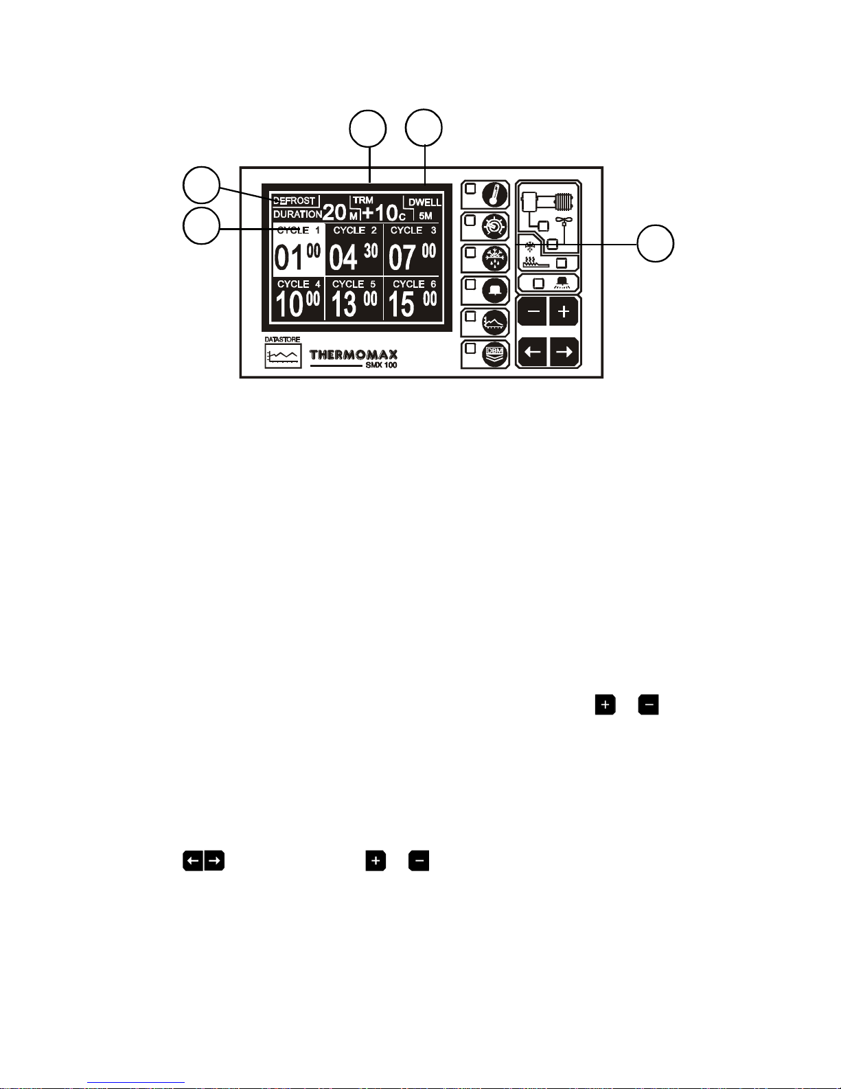
3.4 DEFROSTSCREENS: Real-time Defrost Settings
1DEFROST Function Selector
There are 12 programmable defrost cycles, divided into two groups of 6
cycles.
Defrost Screen 1 shows cycles 1 - 6, and defrost Screen 2 shows cycles 7 -
12. Each group of 6 defrost cycles has its own duration, termination
temperature and dwell period. The defrost cycles can therefore be grouped
into day defrost and night defrost, should the defrosting requirements differ.
To view or set the second group of defrost cycles (cycles 7 - 12) press the
defrost key a second time to reveal Defrost Screen 2.
Where there is a conflict of defrost cycles between group 1 and 2 (i.e. a
defrost cycle start time in group 1 matches a start time in group 2) the group
1 start time will prevail. The defrost cycles may be set at random, i.e. they
need not be set with cycle 1 being the earliest time, then cycle 2 etc.
2Defrost Duration (1 - 99 mins)
The duration of the defrost cycles can be set by pressing the or keys
when this pre-set is highlighted.
Note: As described above, there are two defrost duration pre-sets one for
defrost group 1 (cycles 1 - 6) and one for group 2 (cycles 7 - 12). The first is
displayed / set in Defrost Screen 1, and the second in Defrost Screen 2.
3Defrost Termination Temperature (-50°C to +50°C)
To set the defrost termination temperature, select this preset using the
keys then press the or keys. If the evaporator temperature
exceeds this pre-set during a defrost cycle it will end the current defrost
cycle.
There are two defrost termination temperatures; one for defrost group 1
(cycles 1 - 6) and one for group 2 (cycles 7 - 12).
1
4
3
2
5

15
4Defrost Dwell Timer (0 - 99 min.)
The defrost dwell time is set here.
After a defrost cycle, whether the cycle has terminated by time or
temperature, a dwell period can be programmed (for drain off), or set to ‘0’
(no dwell).
There are two dwell pre-sets; one for cycles 1 - 6 and one for cycles 7 - 12.
5Defrost Start Times
Once the defrost duration, termination temperature and dwell periods have
been set, they apply to all start times within that defrost group.
Each defrost cycle is off (inactive) when the display for that cycle is blank. In
order to program a cycle start time, select the cycle using the keys
then press the or keys to programme the time.
In order to switch off a defrost cycle, set the start time of that cycle to 24:00
(press the key when display reads 23:50 or the key when display
reads 0:00).
3.5 ALARM/ DIAGNOSTIC SCREENS
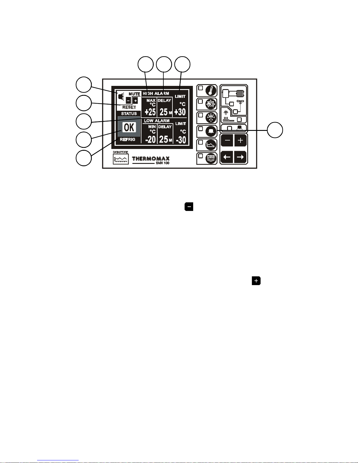
3.5.1 ALARM SCREEN: High & Low Level Alarm Preset
1ALARMFunction Selector
2Alarm Mute
To mute the audible alarm, press the key when MUTE / RESET is
selected.
NOTE: Also, pressing any key the alarm will be temporarily muted for 3
minutes.
When the alarm system is reset, either manually or by the temperatures
dropping back within their allowed limits, the alarm mute will automatically be
cancelled.
3Alarm Reset
Any current activities, delays or counters are reset when the key is
pressed here.
4High alarm Stage 1 temperature (-50°C to +50°C)
The stage 1 alarm is a time / temperature related alarm.
If the maximum threshold is exceeded, a timer is initiated, and no further
action is taken at this time. If, subsequently, the temperature drops below the
threshold, the timer is reset. If following this the temperature rises above the
threshold again, the timer starts again from zero.
5High Alarm Stage 1 Delay (1 - 99 min.)
After the maximum threshold has been exceeded as described in (4) above,
the alarm will not be triggered until the timer exceeds the time delay set
here.
6High Alarm Limit (Stage 2) Temperature (-50°C to +50°C)
If at any time this limit is exceeded the time delays will be overridden and the
alarm will trigger immediately.
16
4
3
7
2
8
9
1
65

17
7Low Alarm
All the functions described in 4 - 6 above also apply to the low alarm.
8Status Window
This window shows the current state of the system.
If there are any warnings or messages, they will be displayed here and, by
referring to the diagnostics screen, further investigations may be carried out
(see 3.5.2). If everything is in good working condition, the message ‘OK’ is
displayed here.
9Cycle Indication
This section of the status window is dedicated to the indication of which cycle
is presently active, i.e. REFRIG (Refrigeration cycle), DEFST (Defrost cycle),
and DWELL.

18
3.5.2 - DIAGNOSTICS SCREEN: System Status Information
1Pressing this switch a second time reveals the diagnostics screen. This
screen is continuously refreshed displaying the current state of the system.
The right margin of the screen displays the message ‘OK’ in front of each of
the system’s units if that unit is in good working condition.
2This is the unique electronic signature of the SMX 100.
3The INPUT TYPE window shows which type of sensor is being used.
(PT100 in this case. PT100 is the only type used by the SMX 100 at present).
4-6 The ROOM, EVAPORATOR and PRODUCT sensor calibration data is shown
there, respectively. This information is for factory use and fault finding only.
Following this, the current temperature is displayed. If the sensor input is
experiencing a fault condition, this is displayed here.
7High Alarm monitor: This display shows the current state of the high alarm
monitor, as well as the history. If there is a stage 1 delay timer in progress,
this will show the time elapsed since the stage 1 maximum threshold was
exceeded. If the alarm has already been triggered, it will show the time
elapsed since it has been triggered. If the high alarm monitor is at rest, it
will show the alarm history, i.e. the last time it was triggered.
8Low Alarm monitor: This display shows the current state of the low alarm
monitor, as well as the history, similar to (7) above.
9Mains-Fail Monitor: This display shows the current state of the mains-fail
monitor, as well as the history. If there is a mains-fail in progress, it will
show the time elapsed since the mains failed. If the mains supply is
present, then the mains-fail history is displayed.
1
3
2
4
5
6
7
8
9

19
3.5.3 DATABANKDIAGNOSTICSSCREEN
1This is the unique electronic signature of the SMX 100.
2The DATABANK window shows the capacity of the internal databank.
3The DAYS FREE window shows the total number of days which have not yet
been ‘used’.
4The PERC FREE window shows the percentage of the databank which has
not yet been ‘used’.
5The TRANSF ON window shows the date on which the contents of the
internal databank need to be transferred.
1
3
4
5
2
Table of contents
Other Thermomax Controllers manuals

Popular Controllers manuals by other brands


cashco
cashco 8310HP Installation, operation & maintenance manual

Gefen
Gefen EXT-HD-VWC-144 user manual

OUMAN
OUMAN EH-800 user manual

Castolin Eutectic
Castolin Eutectic Tri-Safe II Instructions and parts

Honeywell
Honeywell CENTRA LINE EAGLEHAWK NX Installation & commissioning instructions

ECO-WORTHY
ECO-WORTHY 20A PWM manual