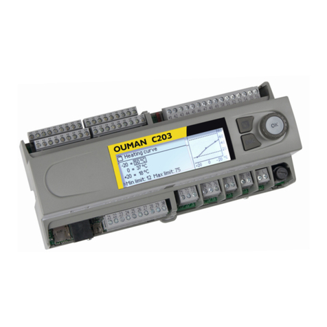
OUMAN EH-800 User manual

1
OUMANEH-800Heatingcontroller
USER MANUAL

2
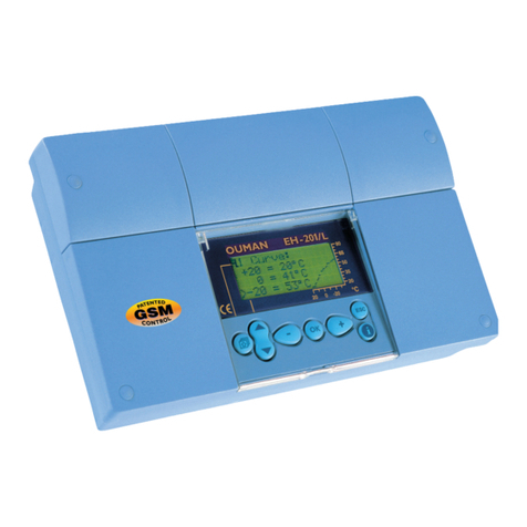
EH-800isaheatingcontrollerforprivatehomesandbusinessfacilitieshavingheatingsystemswithcirculatingwa-
ter.Anextensionunitcanbeobtainedasoptionalequipmentmakingitpossibletotakeasecondcontrolcircuit
intouse.Ifasecondcontrolcircuithasbeentakenintouse,numbers1or2willappearonthemaindisplayindicat-
ingwhichcontrolcircuitisinuse.TheEH-800modelhasanintra/internetconnection(theEH-800Bmodeldoes
nothaveit).
Controlmode:
Automatic
Forced control
Stand-by
Manual control
Temperaturelevel:
Nominal temperature
Temperature drop
Big temperature drop
Pre-increase
Summer stop
(see p. 15 ”Summer function”)
Controlcommand:
indicates what determines the temperature level
Time program
Home/away
H/A
Room temperature
Outdoor temperature
Temp. of water entering the heating circuit
Symbols for heating mode:
Main menu symbols
Control knob
(also the OK
button)
Hand-operated lever
Alarm indicator
Valve control
information
= valve completely open
= valve completely closed
= valve opening
= valve closing
Cancel button
Hand-operated control knob
= floor heating
= radiator heating
OK
Turn the control knob
to navigate in the
menu and carry out
increase and dec-
rease commands.
Press the control button to enter the menu. Press
the control knob (OK function) to conrm changes
Press for a number of seconds special settings that
are seldom needed to appear on the display.
H/A

3
Table of contents
34
34
34
34
34
34
34
35
37
38
40
42
42
43
43
44
46
51
52
53
54
56
59
60
Taking the H2 control circuit into use ....................................
H2 Process settings ...............................................................
Selection of heating mode ............................................
Actuator selection .............................................................
Actuator driving time..........................................................
Selection of type of heating curve .................................
Labeling heating circuits ..................................................
Relay control .............................................................................
Valve ushing ...........................................................................
Text message settings ...........................................................
EH-800 network settings ......................................................
Display settings .......................................................................
Initiation of locking code ........................................................
Changing the locking code ....................................................
Type information ......................................................................
Communication via a mobile phone ............................
Special settings ...............................................................
Optional equipment .......................................................
Installation guide ............................................................
EH-800 connections..........................................................
EH-800 initial setup..........................................................
What to do if there is a fault ..........................................
Index ..................................................................................
Technical information .....................................................
4
5
6
6
7
8
10
11
13
14
14
15
18
18
19
20
20
21
22
22
23
26
26
28
29
30
31
32
Fine adjustment ................................................................
Heating curve settings .....................................................
Säätöpiirikohtainen perusvalikko ..................................
Measurements ..........................................................................
Graphic presentation of meas. history information..............
Supply water info ......................................................................
Room temperature info ............................................................
Settings .......................................................................................
Control modes ...........................................................................
Other controls ...................................................................
Home/Away control...................................................................
Relay control ...............................................................................
Clock functions ..................................................................
Temperature drop Weekly/24-hour program .......................
Exception calendar ....................................................................
Setting the time and date ........................................................
Alarm message .................................................................
Alarms .................................................................................
Device settings ..................................................................
Language/Kieli/Språk ................................................................
Settings for measurement channels ....................................
H1 Process settings....................................................................
Selection of heating mode ...............................................
Direction of valve ................................................................
Selection of type of heating curve ...................................
Labeling heating circuits ....................................................
Cascade control ...................................................................
Hybrid heating........................................................................
Temp. of water entering the heating circuit
= valve completely open
= valve completely closed
= valve opening
= valve closing

4
The ne adjustment function enables you to make small changes
in temperature. It pays to use this function when the room tempe-
rature remains the same but it is too cold or too hot.
Room temperature measurement in use:
When a room sensor is in use, ne tuning directly effects the cal-
culated room temperature + 4°C.
The corrected setting for the room temperature is “Room temperature
setting + “ Fine adjustment” + “Potentiometer (TMR/SP) determined
room temperature setting change”
Room temperature measurement is not in use:
When the room sensor is not connected, ne adjustment effects
the heating curve as a parallel shift and the steepness of the curve
does not change. The effect of ne adjustment on the supply
water temperature can be seen on the bottom row.
Fine adjustment
Instructions:
Press OK in the main display.
Turn the control knob in the desired direction
and press OK to conrm.
Fine adjustment settings can also be inspected and changed in set-
tings (see p. 46).
If outdoor temperature changes effect the room temperature, the
heating curve’s settings must be changed. (see next page).
Too cold
Use the ne adjustment to raise the room temperature.
In this example the room temperature is raised 0.5 C.
Too hot
Use the ne adjustment to lower the room temperature.
In this example the room temperature is lowered 0.5 C.
OK
OK
Heatingneadjust:turncontrolknob
Roomtemperaturechange+0.5 °C
- +
Heatingneadjust:turncontrolknob
Roomtemperaturechange-0.5 °C
- +
Heatingneadjust:turncontrolknob
Roomtemperaturechange+1.5 °C
- +
Info:Effectonsupplywatertemp.6.0°C
Conrm:pressOK,Cancel:pressESC
Heatingneadjust:turncontrolknob
Roomtemperaturechange+0.5 °C
- +
Correctedroomtemperaturesetting22.0°C
Conrm:pressOK,Cancel:pressESC
effects the H1 control circuit.
effects the H2 control circuit.
(only appears if the H2 control circuit has been taken into use,
initiation see p. 34).

5
Heating curve settings
The 3-point curve has automatic curve adjustment! The controller do-
es not allow descending curves or curves that are too concave.
A parallel shift can be made to the heating curve using the ne adjust-
ment function (see p. 48) The 5 point curve is taken into use in process
settings (see p. 29 and 34, how to set a 5 point curve)
The ends of the heating curve are adjusted using the minimum and
maximum limits. The supply water minimum limit setting ensures
that the pipes do not freeze. The maximum limit setting ensures that
excessively hot water that could damage structures (e.g., parquet
with oor heating) does not enter the heating system.
The basis of an even room temperature is a heating curve of the
correct shape. The correct shape depends on many factors. (the
building’s insulation, type of heat distribution, size of the network,
etc.). The supply water temperature for different outdoor temperatu-
res is set in heating curve settings. With Ouman EH-800 the heating
curve can be adjusted exactly to meet the needs of the facility from
either three or ve points. A 3 point curve is the factory setting.
Examples of 3 point curve factory settings:
1. Floor heating, damp rooms
The controller has factory set curves and settings suitable for dif-
ferent heating modes that usually do not have to be changed.
The heating curve needs to be adjusted if the room tempera-
ture does not remain even when the temperature is below ze-
ro and falling.
If the room temp. drops,
make the curve steeper
(set the bigger values
at -20 and 0).
If the room temp. rises,
make the curve less steep
(set the smaller values
at -20 and 0).
Note! Changes effect room temperature slowly
Wait at least 24 hours before readjusting settings. Especially in buil-
dings having oor heating the delays in room temperature changes
are quite long.
The supply water minimum limit setting also ensures a comfortable and good drying
temperature in the summer.
Minimum limit
Maximum limit
4. Radiator heating, steep heating curve
3. Radiator heating, normal heating curve
2. Floor heating, normal heating curve
H1Heatingcurve
-20 = 58°C 62°C
0 = 41°C 43°C
+20 = 18°C
Min.limit:12Max.limit:75 +20 -200°C
20
40
60
80
H1Heatingcurve
-20 = 58°C 54°C
0 = 41°C 39°C
+20 = 18°C
Min.limit:12Max.limit:75 +20 -200°C
20
40
60
80
H1Heatingcurve
-20 = 31°C
0 = 27°C
+20 = 23°C
Min.lilmit:23Max.limit:35 +20 -200°C
20
40
60
80
H1Heatingcurve
-20 = 33°C
0 = 27°C
+20 = 20°C
Min.lilmit:12Max.limit:42 +20 -200°C
20
40
60
80
H1Heatingcurve
-20 = 58°C
0 = 41°C
+20 = 18°C
Min.lilmit:12Max.limit:75 +20 -200°C
20
40
60
80
H1Heatingcurve
-20 = 63°C
0 = 44°C
+20 = 18°C
Min.lilmit:12Max.limit:75 +20 -200°C
20
40
60
80
effects the H1 control circuit curve.
effects the H2 control circuit curve.
(only appears if the H2 control circuit has been taken into use,
initiation see p. 34).

6
Basic menu: Measurements
Present temperature of water entering the heating network.
Present measured outdoor temperature.
Present room temperature.
Present temperature of water returning form the heating network.
Measurement channels 3, 4 and 5 can be used as free temperature measurements. If the me-
asurement has not been labeled, it appears as “Measurement 3 (4)”. Measurement channel 5
is in use if an extension unit is connected to the controller.
Present position of the valve.
If cascade control is in use, the controller’s display indicates into which position the controller is mo-
ving the valve at the present.
The controller uses the average temperature of the previous day (24 hour period) e.g., when the
outdoor sensor malfunctions.
The average outdoor temperature that the controller uses for control. (setting the average
p. 12).
The average room temperature that the controller uses for control (see p. 44).
0...+130°C
-50...+50°C
-10...+80°C
0...+130°C
0...+130°C
0....100%
0....100%
-50...+50°C
Supply water temperature
Outdoor temperature
Room temperature
Return water temperature
Measurement 3 (4, 5)
(can be labelled)
Valve position
Cascade valve control
Outdoor ave. temp (prev. day)
Delayed outdoor temp.
measurement
Delayed room temp.
measurement
Measurement Range Measurement information
The measurements menu displays present information about connected sensors and valve posi-
tions. A factory set supply water sensor is connected to the controller. It has a separate plug-in for
outdoor temperature. Information about measurement channels 3 and 4 on pages 23-25. Measu-
rements 5 and 6 are also in use if an extension unit has been connected to the controller. Connect
the supply water sensor of the second heating control circuit (H2) to the extension unit (EXU-800).
When you take the H2 control circuit into use in process settings, automatically reserve measure-
ment 5 of the EH-800 controller for H2 control water heating measurement.
If a GSM is connected to the controller, you can read measurement information form a mobi-
le phone.Send a message: Measurements.
The controller sends the present measurement information to your mobile phone. (If you
have a device ID, write the device ID in front of the key word, e.g., TC01 Measurements)
Key word:
Measurements
Basic menu -> Measurements
> Measurements
H1Supplywatertemperature 35.1°C
Outdoortemperature -18.2°C
H1Roomtemperature21.5°C
H2Supplywatertemperature32.5°C

7
Graphic presentation of measurement history information
Temperature measurement trend display:
Press OK at a temperature measurement, a trend display will appear
for that measurement.
Use the control knob to browse measurement history. The exact
measurement and time and date will appear at the top edge of the
display next to the cursor. As a factory setting, temperatures are sa-
ved every ten minutes (=600 s). Press OK to alternately zoom in or
zoom out the trend display. In case sampling interval is 10 minutes
(600 s), the distance between the vertical lines is either 10 minutes
or 1 hour. In this case, the controller’s memory contains history in-
formation from the last 10 days. You may change trend sampling in-
terval if you wish (Device settings -> Measurement channel settings,
p. 23) Press ESC to exit the trend display.
Use the trend display to easily monitor, e.g., temperature drops and
room temperature levels. You can also check outdoor temperatu-
res from the trend.
Basic menu -> Measurements -> Press OK at measurement information
H1-supplywater28.0108:26:19[34.7°C](5h)
38
28
The controller automatically ushes and calibrates the valve
once a week on (as a factory setting Monday at 08 am).The
controller rst completely closes the valve and then if the
ush function has been taken into use it opens it to the ush
position and then to the position determined by the control-
ler (see Device settings > Valve ushing, p. 35)
Automatic scaling according to the measured tempe-
ratures (28 ... 38°C in the example).
H1 Supply water temperature curve
Inspection moment (use the control knob to select the moment)
Supply water temperature (34.7 °C)
at the selection moment
H1Supplywater28.0108:26:19[34.7](5h)
38
28
The length of
the time period
on the display
You may download a trend le from EH-800 device to your pc via
controller web page and examine the trend chart on your pc display.
You may use Ouman Trend software to look at a trend le as a chart.
Go to www.ouman. to download the software.

8
Supply water temperature according to the curve at the present outdoor temperature.
Effect of the oor heating anticipate function on the supply water temperature (see p. 12).
The delaying effect of the outdoor temperature measurement on supply water control calculated
from the monitoring time period (see p 12).
Effect of ne adjustment on the supply water temperature
Effect of room compensation on the supply water
Additional ne adjustment to room compensation based on present control (effect of l control)
Effect on the supply water temperature of a temperature drop or big temperature drop by the week
clock control or exception calendar control.
Effect of ”Away” control on the supply water temperature. The switch, SMS, or control row
indicates where the home or away command has come from. For example, Home/Away SMS,
mobile phone control.
Effect of automatic autumn drying on the supply water temperature (se p. 48).
The supply water info shows which factors are effecting the supply water temperature at
the time of inspection. The starting point is the supply water temperature according to the
outdoor temperature (according to the heating curve). For example, if you see a temperature
drop in the supply water info you can determine which settings may be incorrect (e.g., mini-
mum or maximum limit settings).
According to the example in the diagram the supply water is 35.1°C. The supply water setting has
been adjusted 5,9 °C.using the ne adjustment. According to these the calculated supply water set-
ting is 41.0°C (=35.1 + 5.9).
Supply water according to curve
Effect of oor heating anticipate
Effect of outdoor temp. delay
Effect of ne adjustment
Effect of room compensation
Room compensation time adjustment
Time program effect on supply water
Home/Away control by switch
Home/Away control by SMS
Home/Away control by controller
Effect of autumn drying
Basic menu: Supply water info
Factors effecting the supply water temp.
Basic menu -> H1 (H2) Supply water info
HInt: If the room compensation’s time adjustment always adjusts the room temperature in the same
direction, e.g., +3°C when the outdoor temperature is below zero, it means that the curve has been
set too low. In this example, the supply water curve must be raised at -20°C outdoor temperature.
Explanation
>H1Radiatorheating...H1Supplywaterinfo
Supplywateraccordingtocurve 35.1°C
Effectofneadjustment 5.9°C
Calculatedsupplywatersetting 41.0°C

9
The controller controls the supply water temperature to its calculated setting.
Key words:
H1 Supply water info
H2 Supply water info
Send a message: H1 Supply water info.
The controller sends a supply water info from the H1 heating circuit to your mobile phone that
shows you the controller determined supply water temperature at the present and the factors ef-
fecting supply water control. The message cannot be changed or sent back to the controller.
Effect of maximum limit
Effect of minimum limit
Effect of return water compensation
Stand-by
H1 Summer function
Outdoor temp. limits the drop
Calculated supply water setting
Effect of setting delay
Supply water temperature
Supply water temperature drop due to the maximum limit.
Supply water temperature increase due to the minimum limit.
Both the general minimum limit set for the supply water and -20°C outdoor temperature effect the mi-
nimum limit.
Effect of the return water limiting functions on the supply water. If the return water temperature
drops below the lower limit the supply water temperature is raised and if the return water tem-
perature rises above the maximum limit the supply water temperature is lowered. The return
water temperature measurement can be taken into use only in the H1 control circuit.
Lowering effect of free temperature drop on supply water temperature
The controller closes the valve in summer function.
The effect of the temperature drop block on the supply water temperature (see p. 45)
Present supply water temperature determined by the controller. All the factors are considered
that affect the supply water temperature.
Effect of the limit set for the speed of change of the supply water setting on the supply water
temperature. (see p. 48).
Present measured supply water temperature.
Factors effecting the supply water temp. Explanation
Supply water info

10
Factor effecting the room temperature
Delayed room temperature that the controller uses in control (see p. 46).
Room temperature setting set by the user.
Effect of ne adjustment on the room temperature setting (see p. 4 and 48).
Room temperature setting change by the potentiometer (only in H1).
Room temperature drop by week clock or exception calendar.
Room temperature change controlled by the Home/Away switch.
Effect of a “Home” or “Away” command by a mobile phone on the room temperature.
Effect of a “Home” or “Away” control by the controller on the room temperature
Effect of automatic autumn drying on room temperature.
Present room temperature setting determined by the controller.
Example.
The room temperature has been set at 21.0°C.
Fine adjustment raises the temperature 0.5°C.
The controller sets the calculated room temperature at 21.5°C (=21.0+ 0.5).
Basic menu -> H1 (H2) Room temperature info
Delayed room temp. measurement
Room temperature setting
Effect of ne adjustment
Effect of potentiometer
Time program effect on room temp.
Home/Away control by switch
Home/Away control by SMS
Home/Away control by controller
Effect of autumn drying
Calculated room setting =
Explanation
>H1Radiatorheating>Basicmenu
Measurements >
Supplywaterinfo >
Roomtemperatureinfo >
Settings >
>H1Radiatorheating...Roomtemperaturinfo
Roomtemperatursetting 21.0°C
Effectofneadjustment 0.5°C
-----------------------------------
Calculatedroomsetting21.5°C
Basic menu: Room temperature info
If a room sensor is connected to the controller, you can check the room temperature info to
see which factors determine the room temperature at the time of inspection.
Key words:
H1 Room temperature info
H2 Room temperature info
Send a message: H1 Room temperature info. The controller sends a room temperature info
from the H1 heating control circuit to your mobile phone that shows you the calculated room
temperature setting that can be used in control. The message can’t be changed or sent back
to the controller.

11
Basic menu: Settings
The EH-800 controller’s settings are divided into two groups; main settings and less frequent-
ly adjusted special settings which can be seen by pressing OK for a number of seconds. The-
se settings are set into the settings menu. Press OK again for a number of seconds to hide
the settings.
Changing a setting: Turn the control knob until the setting to be changed appears against a
black background. Press OK to open a new window in which the changes are made. Press Esc
to exit..
Locking settings: Lock the settings to prevent unauthorized persons from changing settings.
The controller will then ask for the locking code before it lets you change settings. (see p. 42).
This section illustrates main settings. Special settings are illustrated on pages 46-50.
Can be set when the heating mode is the constant temperature controller.
Basic room temperature setting for the controller set by the user. The room temperature can be
set when room temperature measurement has been taken into use. The room temperature set-
ting range can be increased or limited between 0.0...95.0 °C (see room temperature setting ran-
ge min/max, p. 47 in special maintenance settings).
Amount of temperature drop set by the user.
(factory setting; 6 °C with radiator heating, 2 °C with oor heating).
If room temperature measurement has been taken into use, the temperature drop is given di-
rectly as a room temperature drop.
A big temperature drop set by the user (factory setting; 16 °C with radiator heating, 6 °C with
oor heating). If room temperature measurement has been taken into use, the big temperatu-
re drop is given directly as a room temperature drop.
0.0...95.0°C
5.0...50.0°C
(0.0...95.0°C)
0...90°C
0...90°C
0...90.0°C
0...90°C
0...90°C
0...90.0°C
15.0°C
21.0°C
6°C
2°C
1.5°C
16°C
6°C
5.0°C
Supply water setting
Room temperature
Temperature drop
Supply water (radiator h.)
Supply water (oor h.)
Room temperature
Big temperature drop
Supply water (radiator h.)
Supply water (oor h.)
Room temperature
Setting: Factory-
setting
Range: Information about settings:
Basic menu -> H1 (H2) Settings
Temperature drops can be activated by the controller’s time program, home-away
function or the controller’s forced control.
>H1Radiatorheating>Settings
Roomtemperature 21.0°C>
Temperaturedrop(roomtemperature) 1.5°C>
Bigtemperaturedrop(roomtemp) 5.0°C>
Supplywaterminlimit 12.0°C>
Roomtemperature
21.0°C
min:0.0max:95.0

12
Key words:
H1 Settings
H2 Settings
Send a message: Settings. (If you have a device ID, write the device ID in front of the key word,
e.g., TC01 Settings). The controller sends the present settings to your mobile phone.
If you want to change settings, write the new setting in place of the old setting and send a mes-
sage back to the controller. The controller sends the setting as a return message. You can check
the message to see that the setting has been changed.
Settings
5.0...95.0°C
0.0...95.0°C
5...95°C
0...15h
Not in use
...5...95°C
-
0...6h
12.0°C
12.0°C
23.0°C
12.0°C
75°C
42°C
35°C
2h
19°C
-
2h
Supply water minimum limit
radiator heating
oor heating normal
oor heating damp rooms
constant temp. contoller
Supply water maximum limit
radiator heating
oor heating normal
oor heating damp rooms
Outdoor temp.
measurement delay
Summer function
(outdoor temp. limit)
Floor heating anticipate
radiator heating
oor heating
Minimum allowed supply water temperature. A higher minimum temperature is used in damp
rooms and tiled rooms than in, e.g., rooms having a parquet oor to ensure a comfortable tem-
perature and removal of moisture in the summer.
Maximum allowed supply water temperature. The maximum limit prevents the temperature
in the heating circuit from rising too high, preventing damage to pipes and surface materials.
If, e.g., the characteristic heating curve setting is incorrect, the maximum limit prevents exces-
sively hot water from entering the network.
The length of the outdoor temperature measurement monitoring period from which the control-
ler calculates an approximate average. Supply water temperature control occurs on the basis of
the measurement of the average. The factory setting for the radiator heating delay is 2 hours and in
oor heating (0h) the delay is not used. If the temperature is below zero and falling and for a period
of time the room temperature rises too high or if the weather warms up and for a period of time the
room temperature falls too low, increase the outdoor temperature delay time. If the opposite hap-
pens, decrease the delay time.
The outdoor temp. limit at which the H1 control valve is closed. (pump stop see p. 15). The setting
is the same for control circuits H1 and H2. The summer function is inactivated when the outdoor
temp. is at least 0,5° C below the setting and the clearance delay has ended (clearance delay see p.
49) If oor heating for damp rooms is in use, the factory setting for the summer function is “not in
use”. The summer function is inactivated if the supply water freezing risk gives an alarm. This set-
ting can be set in the H2 control circuit only if ”closed” has been selected for the valve position in
summer function (see p. 49)
Floor heating anticipate attempts to minimize changes in room temp. when the outdoor temp. chan-
ges. In oor heating, the concrete slows the transfer of heat into the room. Floor heating anticipa-
te minimizes changes in room temp. when the outdoor temp. changes. If the temp. is below zero
and falling and for a period of time the room temp. falls too low or if the weather warms up and for
a period of time the room temp. rises too high, increase the outdoor temp. delay time. If the oppo-
site happens, decrease the delay time.
Setting Factory-
setting
Range Information about settings
Note! Some of the settings (special settings) are hidden. Press OK for a number of seconds to alternately make them appear or disappear.

13
Basic menu: Control modes
Automatic
Forced control, nominal temp.
Forced control, temp. drop
Forced control, bigger temp. drop
Manual electrical
Stand-by
The selected control mode always appears in the controller’s basic display.
Changing the control mode: Turn the control knob to move to control mode in the basic display.
The selected control mode appears in the display. Press OK to open a new window. Turn the
control knob and press OK to select the desired control mode. Press ESC to exit.
Control mode Explanation
EH-800 controls the supply water temperature automatically according to
the need for heating and possible time programs and home-away cont-
rol commands. Automatic control is the recommended control mode.
Continuous nominal temperature.
Continuous temperature drop
Continuous big temperature drop
The valve remains in that position until manual control has been turned off. The measured
H1 valve position appears in the controller’s display. If cascade control is in use, the control-
ler can move the H1 valve into the desired position using the actuator connected to EH-800.
The controller can also move the cascade control valve into the desired position. If casca-
de control is in use and you switch the controller to manual via a mobile phone, the % that you
give represents the combined positions of the valves. Examples: 100% = both valves complete-
ly open. 50% = the valve connected to EH-800 is closed and the cascade control valve is complete-
ly open. 30% = the valve connected to EH-800 is closed and the cascade control valve is 60% open.
The controller lets the supply water temperature drop freely to the freezing limit.
Manual mechanical Unplug the controller from the power source. The EH-800 cont-
roller also has a mechanical hand-operated lever. Press the cont-
rol knob (1) and turn the lever (2) simultaneously.
The position of the hand-operated lever indicates the position
of the valve.
None of the time programs are in
effect with forced drive.
Send a message: H1 Control modes. The controller sends a return message in which a * ap-
pears in front of the control mode in use. If you want to change the control mode, move the *
in front of the desired control mode and send the message back to the controller. The controller
will then send a return message showing that it has switched to the desired control mode.
Key words:
H1 Control modes
H2 Control modes
Basic menu -> H1 (H2) Control modes
2.
1.
Radiatorheating>Basicmenu
Supplywaterinfo>
Roomtemperaturinfo>
Settings>
Controlmode >
Valve ushing and valve calibration run is once a week (see p. 37).
Radiatorheating...Controlmodes
ControlmodeManual,el.>
Cascadecontrolvalvecontrol 20%>
H1Valvecontrol: 15%>
H1valveposition15%

14
Home/Away control (H/A)
When a home control command is received, the controller by-passes the present temperatu-
re drop command in use and switches to nominal temperature.
An away control command causes the controller to switch to temperature drop. The control-
ler switches to a big temperature drop if the week program or exception calendar controls it
to a big temperature drop.
In the no Home/Away control mode the controller is on automatic control and follows the
week program and exception calendar. If time programs have not been made, the controller
is in the nominal temperature mode.
Home
Away
No H/A control
Home/Away control Explanation
The “Home” and “Away” controls can only be used if the controller is on automatic control.
The control command can be given from the controller’s menu, from the home/away switch
connected to the controller or from a mobile phone. Regardless of from where the control
command comes, the controller’s Home/Away display is updated. The last control command
is in use. The control command affects both H1 and H2 control circuits.
Key words:
Home
Away
The Home/Away control is only in effect if the controller is on automatic control.
When you send a Home or Away message, the controller sends back an OUMAN mes-
sage showing that the HOME or AWAY control is on.
Muut ohjaukset -> Home/Away control
Example 1. The controller does not have a week program or exception calendar program:
An “Away” command causes the controller to switch to a temperature drop.
A “Home” command causes the controller to switch back to a nominal temperature mode.
Example 2. The controller has a week program:
An “Away” command causes the controller to switch from the weekly program to a temperature drop.
A “Home” command causes the controller to switch to a nominal temperature mode and then begin temperature drops
according to the weekly calendar.
Example 3. The temperature drop has been made with the exception calendar and you want to temporarily switch to a nominal
temperature.
A “Home” control causes the controller to switch to the nominal temperature mode.
An “Away” control command causes the controller to switch back to a temperature level controlled by the exception calendar.
Home/Awaycontrol
Home
NoH/Acontrol
Away

15
Other controls: Relay control
The controller stops the pump when the outdoor temperature rises above the “Summer func-
tion (outdoor temp. limit)” (see p. 35). Go to H2 control circuit special settings to select whet-
her the H2 control circuit is to be actively controlled during pump summer stop or whether
the H2 control circuit valve is to be at the minimum limit (see p.49). During the period when
the pump is stopped it runs once a week during valve ushing to prevent the valve from be-
coming stuck (see p. 37). The pump runs when the controller is without operating voltage
(230V). If “ON” has been selected, the pump runs continuously and the relay is open. If “OFF”
has been selected the pump is stopped. If ”Auto” has been selected, pump runs according
to the outdoor temperature.
The controller’s device settings determines which temperature measurement controls the re-
lay and whether relay control begins when the temperature rises or falls to that setting. The
controller’s display shows you which temperature measurement information relay control
uses, the temperature measurement information and the present state of the relay. Examp-
les:
1. When the boiler temperature rises above the setting the controller switches on the char-
ging pump and collects heat into the accumulator. When the boiler temperature drops below
the setting the amount of the hysteresis, the charging pump is switched off.
2. The controller switches on an additional heat source (e.g., an electric heater), when the tem-
perature of the boiler drops below the setting and switches off the electric heater when the
temperature of the accumulator rises the amount of the hysteresis above the setting.
Pump summer stop:
Relay control according to the temperature:
Relay use Explanation
Relay control is in use if an extension unit is connected to the controller. Relay control is ta-
ken into use from the controller’s device settings. Relay control can be used to stop the pump
for the summer. or the relay can be controlled according to the temperature, temperature
difference, position of the valve or the time program. If hybrid heating has been taken into
use, the controller reserves the relay for charge pump control. Normally, the relay’s control
mode is automatic. If necessary, the relay can be force controlled ON or OFF.
Other controls -> Relay control
>Othercontrols
Home/AwaycontrolNoH/Acontrol>
Relaycontrol>
>Othercontrols>Relaycontrol
RelaycontrolPumpsummerstop
ControlmodeAutomatic>
Summerfunction(outdoortemp.limit)17°C>
PumpstateRun
>Othercontrols>Relaycontrol
RelaycontrolAccordingtothetemperature
ControlmodeAutomatic>
Settingatwhichtherelayisactive(ON)58°C>
Hysteresis4°C >
Temperaturofboiler67°C
RelaycontrolmodeON

16
Relay control
Two different temperatures are compared, e.g., the temperatures of the solar collector and ac-
cumulator. When the temperature difference is large enough, e.g., 10 °C, the solar collector’s
circulating pump is switched on. When the temperature difference drops to, e.g., 3 °C, the cir-
culating pump is switched off.
Relay control is switched on (ON) when the valve opens to the set setting. Relay control is
switched off when the valve position is at the OFF setting. The present actuator position and
relay mode can be seen from the controller’s display.
Select the energy mode according to H1 control valve’s control information.
Relay use Explanation
Other controls -> Relay control
>Othercontrols>Relaycontrol
RelaycontrolAccord.toH1valveposition
ControlmodeAutomatic>
Valvepositionwhererelayisactive95%>
Valvepositionwhererelayisreleased90%>
H1Valveposition85%
RelaycontrolmodeOFF
>Othercontrols>Relaycontrol
RelaycontrolAccord.tothetemp.difference
ControlmodeAutomatic>
Temp.ofsolarcollector(A)68.3°C>
Temperaturofaccumulator(B)55.4°C>
Temp.diff.(A-B)whererelayisactive10°C>
Temp.diff.(A-B)whererelayisreleased3°C>
RelaycontrolmodeON
Relay control according to the temperature difference:
Relay control according to the H1 Valve position:
Example: The water in the boiler is rst warmed using inexpensive energy (e.g., air-to-water heat
pump) When EH-800 has almost completely opened the control valve (e.g., 95%) the relay is activa-
ted (ON) and the oil burner receives a running permit. When the heating need decreases the control-
ler starts closing the valve. The oil burner’s running permit is inactivated when the valve has closed
to the point at which the relay switches to the OFF mode (e.g., 90%).
0 % 100%90% 95%
Valve position Oil burner
running permit
Relay ON
Relay OFF
Othercontrols>Relaycontrol
RelaycontrolGeneralalarm
RelaycontrolmodeOFF
When any of the alarms is activated in the device, also the sum/common alarm is activated.
The common alarm does not indicate, which alarm in the device is active. When any of the
alarms is unacknowledged, the relay is active.
An example: If EH-800 is installed in a separated room, the information of the controller`s alarm can
be transmitted to the accommodation by connecting e.g. an indicator lamp or a siren to the relay.
When the controller alarms, the indicator lamp or the siren indicates the alarm.
General alarm:

17
TimeRelaymode
22:00RelayON
06:00RelayOFF
00:00Addnew
MTWTFSS
OK
Relayweeklycalender:Edit,pressOK
0 3 6 9 12 15 18 21 24
Monday>
Tuesday >
Wednesdy>
The relay changes its mode according to its week/24 hour program. The controller’s display
shows the present control mode. The relay’s week/24 hour program can also be found under
clock programs. Set the time for relay control. Select the mode for the relay at the set time.
Then select the days of the week that relay control is to be used.
Example: The oor is heated using night time electricity.
Creating the week/24 hour program for the relay:
Press OK at the “Add new” row.
Press OK. Set the time for relay control (set the hours and minutes separately) and Press OK
to conrm the time.
Press OK, then turn the control knob to set the mode for the relay and press OK to conrm.
Press OK at each day of the week that the control command is to be set for. Press OK at the
end of the row to conrm the new time program. Press ESC to exit.
In the example, relay control is activated Sunday - Friday from ten p.m. to six a.m.
Relay control according to the time program:
Relay use Explanation
>Othercontrols>Relaycontrol
RelaycontrolAccord.tothetimeprogram
ControlmodeAutomatic>
Relayweekly/24-hourprogram>
RelaycontrolmodeON
Key word:
Relay control
Send a message: Relay control. The controller sends a return message with a * in front of the
control mode in use (auto/ON/OFF). If you want to change the control mode, move the * in front
of the desired control mode and send a message back to the controller. The controller sends
a return message showing that the controller has changed the control mode.
Two temperatures are compared, e.g. solar collector temperature and accumulator tempera-
ture. When the temperature difference grows big enough (e.g. 10°C), the solar collector charge
pump starts. When the temperature difference gets small enough (e.g. 2 °C), the pump stops.
In hybrid heating, the relay is used to control the charge pump:
Othercontrols>Relaycontrol
RelaycontrolChargepumpcontrol
ControlmodeAutomatic>
Temp.ofsolarcollector(A)66.3°C
Temperaturofaccumulator(B)55.4°C
Temp.diff.(A-B)whererelayisactive50°C>
Temp.diff.(A-B)whererelayisreleased30°C>
RelaycontrolmodeON

18
TimeTemp.level
06:00Nominaltemp.
17:00Temperat.drop
00:00Addnew
MTWTFSS
OK
The week program is used to make temperature drops occurring at
regular intervals. The week program can be seen from the graph or
the edit display. The bars on the graph indicate when the tempera-
ture drop is active and the switch times appear at the bottom.
Temperature drop Weekly/24-hour program
Browsing the week program:
An edit display will open up which displays all the switch times and
also the heating mode and days of the week of the switch times.
Clock functions -> H1 (H2) Weekly/24-hour program
Graph
An edit display
The example shows a week program for an ofce with a temperatu-
re drop Monday – Friday from 5 pm to 6 am.
Turn the control knob to the switch time you want to delete and press
OK. Press OK at temperature level and select ”Delete switch time”
and press OK at the end of the row.
Press OK at the “Add new” row.
Press OK. Set the switch time (set hours and minutes separately)
and press OK.
Press OK and then turn the control knob to set the temperature le-
vel and press OK. Press OK at each week day to set the days of the
week. Press OK at the end of the row to conrm the new time pro-
gram. Exit with ESC.
Adding a new switch time:
Deleting a switch time:
1. Set the
switch time
2. Set the desired
temperature
3.Select the day of the week
Turn the control knob to move the frame to the value you want to
change and press OK. The value to be changed will have a black
background. Press OK. Made the change and press OK. Exit with
ESC.
Editing the week program:
Turn the control knob to browse the week program. If you want to
see exact switch times or you want to change, delete or add switch
times, press OK at some day of the week.
TimeTemp.level
06:00Nominaltemp.
17:00 Deleteswitchtime
00:00Addnew
MTWTFSS
OK
H1Weeklycalender,Edit:PressOK
0 3 6 9 12 15 18 21 24
Tuesday >
Wednesdy>
Thursday > H1Weeklycalender,Edit:PressOK
0 3 6 9 12 15 18 21 24
Friday >
Saturday >
Sunday >
Clockfunctions
09:02
Fr05.02.2009
TimeTemp.level
06:00Nominaltemp.
17:00 Temperat.drop
00:00Addnew
MTWTFSS
OK

19
Temperature drops lasting over a week or temperature drops that
differ from the normal week program are done with thespecial ca-
lendar. The special calendar is stronger than the week calendar.
It is easy to make a temperature drop with the special calendar,
e.g., when going on a vacation for a longer period of time. If the
controller’s pre-increase function has been taken into use, set the
time you are returning home as the end time. Select “Automatic” at
the ending time . The pre-increase ensures that a nominal tempera-
ture will been reached at the ending time (see p. 47).
The control command symbol that appears in the EH-800 controller’s
basic display automatically changes according to what is controlling
heating levels. When the control command comes from the set ti-
me program (week/24 hour clock or special calendar), a symbol of a
clock appears in the main display. The amount of temperature drop is given in settings (see p. 11).
The pre-increase function can be used when switching from a tem-
perature drop to a nominal temperature. (see p. 47)
In this example, there is a big temperature drop from 21.12.2009 to
03.01.2010 and then the controller switches to a nominal temperatu-
re mode if the week program or Home /Away control doesn’t cont-
rol the temperature drop.
A temperature drop for a certain length of time is made using the
exception calendar as follows:
Move to exception calendar and press OK. Press OK at the “Add
new” row. Press OK and set the time (date and time), for the tempe-
rature drop to begin. Press OK.
Press OK at the mode row and select the mode for the controller to
switch to at the above set time. You can select “Temperat. drop”, “
Bigger temp. drop” or “ Contin. nominal temperat.”.
Press ” Ready” to conrm exception calendar control.
The Home/Away control is only in effect if the controller is on auto-
matic control. When you send a Home or Away message, the cont-
roller sends back an OUMAN message showing that the HOME or
AWAY control is on.
Deleting a temperature drop from the exception calendar:
Select the switch moment to be deleted at mode
“Delete switch time” and select “Ready” to conrm.
Special calendar
Clock functions -> H1 (H2) Special calender
Key word:
Exception calendar
Exception calendar: (#1) 21.12.09 08:00 BIGGER DROP/
03.01.10 16:00 AUTOMAATTI/dd.mm.yy hh:mm mode/
Date Time Status
dd.mm.yy hh:mm mode
Mode (status):
BIGGER DROP = bigger temperature drop
DROP = temperature drop
AUTOM = automatic control
CONTIN. NOMIN. = continuous nominal temperature
Specialcalendar:Add/changeconnectiontime
Day: 21.12.2009
Time: 11:30
Mode: Bigtemp.drop
Approve: Ready
Day Time Specialcalendarmode
21.12.2009 08:00 Bigtemp.drop >
03.01.2010 16:00 Automat >
00.00.0000 00:00 Addnew >
Clockfunctions
H1Weekly/24-hourprogram >
H2Weekly/24-hourprogram >
H1Specialcalender >
H2Specialcalender >

20
Time
19:44
tt:mm
Givethehours;
Time and date
First set the day and press OK to conrm.
Next set the month and press OK to conrm.
Then set the year and press OK to conrm.
The day of the week will automatically be updated on the display.
Press ESC to exit from the time setting mode.
Setting the date
The hours and minutes can be set separately
Set the hours and press OK to conrm.
Set the minutes and press OK to conrm.
It is important that the time and date are correct, because, e.g.,
in alarms you can see when the alarm has become activated and
when it has become inactive.
The controller’s clock automatically makes summer time and stan-
dard time changes and registers leap years. The clock has a backup
system in case of short power failures.
Clock functions ->Time and date
If there are a number of unacknowledged alarms in the controller,
acknowledge the alarm appearing on the display and the previous
alarm will appear. When all possible active alarms have been ack-
nowledged, the alarm window will disappear from the display and
the alarm will no longer sound.
Alarm notice
The controller can give an alarm for many reasons. In the event of
an alarm, an alarm window pops up which displays exact alarm in-
formation.
Dangeroffreezingalarm
Supplywatertemperature10.2°C
Received:08.11.2008klo02:27
Presscontrolknobtoacknowledgedthealarm.
Acknowledging alarms: Press OK. If the cause of the
alarm has not disappeared, the exclamation mark in
the right upper will blink.
Ifitistoocoldorhot,pressOK
Contrlmode:Automat
Temp.level 22
9
33
Kellonajan asettaminen
Date
Mon19.09.2011
pp.kk.vvvv
Givetheday
Clockfunctions
H1Specialcalender >
H2Specialcalender >
Time 20:52
Date Mon19.09.2011
Other manuals for EH-800
2
This manual suits for next models
2
Table of contents
Other OUMAN Controllers manuals
Popular Controllers manuals by other brands

Banner
Banner Two-Hand-Control DUO-TOUCH SG brochure

AS Torantriebe
AS Torantriebe R50 24V Operating and installation instructions

Gigarise
Gigarise SE2000 SERIES instruction manual

Allen-Bradley
Allen-Bradley PLC-3 Series quick start

YASKAWA
YASKAWA MOTOMAN Series instructions

Ascon tecnologic
Ascon tecnologic K 1E Series Engineering manual