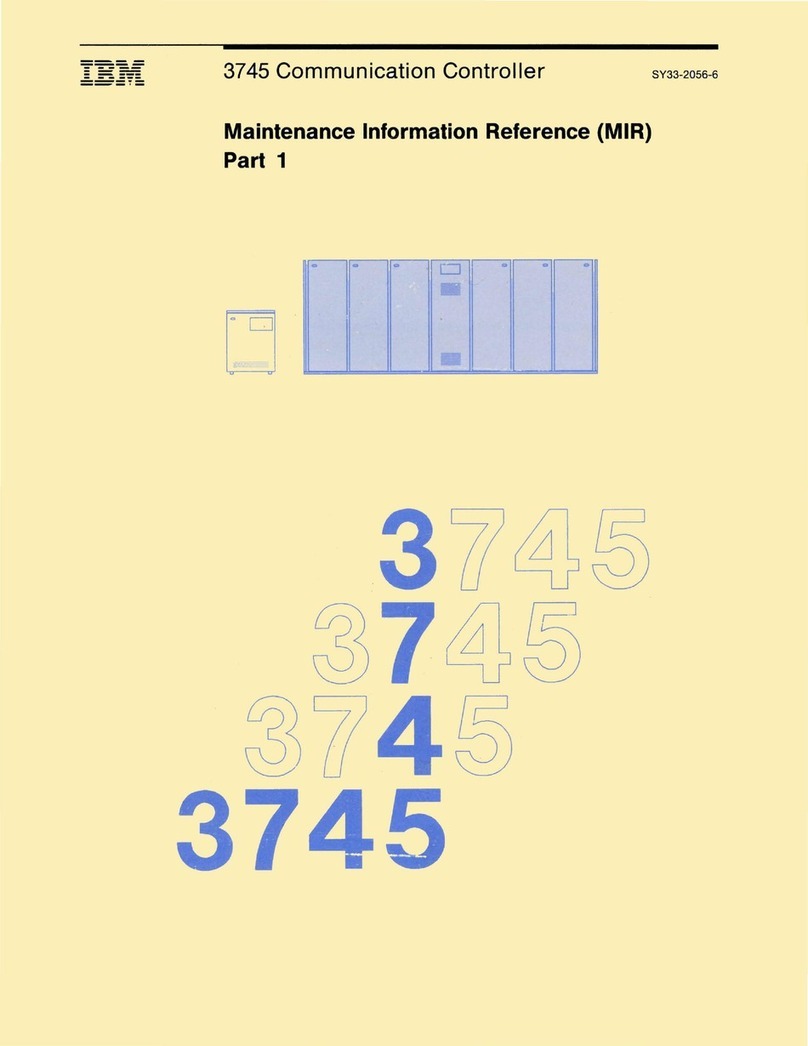
IBM 3745-130 User manual

----
----
- -
---
---
--
---
- - -
---
3745 Communication Controller SY33-2067-3
-----
--_
.-
Installation Guide
'"
D

----
----
--
---
---
--
---
------
-----
---'-
IBM
3745
Communication Controller
Models
130, 150,
and
170
Installation Guide
SY33-2067
-3

Note!
------------------------------------------------------------------~
Before
using
this
information
and
the
product
it
supports,
be
sure
to
read
the
general
information
under
"Notices"
on page vii.
Fourth Edition (August 1991)
The
information
contained in
this
manual
is
subject
to
change
from
time
to
time. Any such changes
will
be
reported
in subsequent revisions.
Changes
have been
made
throughout
this
edition, and
this
manual
shoul·d be read
in
its entirety.
Order
publications
through
your
IBM
representative
or
the
IBM
branch
office serving
your
locality.
Publications
are
not stocked at the
addresses
given below.
A form
for
readers'
comments
appears
at
the
back
of
this
publication.
If
the
form has been
removed,
address
your
comments
to:
International
Business Machines
Corporation
Department
6R1
LG
180 Kost Road
Mechanicsburg
PA
17055-0180
U.S.A.
or
IBM France
Centre
d'Etudes et Recherches
Service
0762 BP
79
06610 La Gaude
France
When you send information to IBM. you
grant
IBM a
non-exclusive
right
to
use
or
distribute
the
infor-
mation
in any
way
it believes
appropriate
without
incurring
any
obligation
to
you.
© Copyright International Business Machines Corporation 1989, 1991. All rights reserved.
Note
to
U.S. Government Users -
Documentation
related
to
restricted
rights
-Use, duplication
or
dis-
closure
is
subject
to
restrictions set forth in GSA ADP Schedule Contract
with
IBM Corp.

Contents
Chapter
1.
Installation
Procedures
Preparing
to
Install
the
3745
...
3745
Component
Locations (Front)
3745
Component
Locations (Rear)
3745 Installation
.........
.
Setting LlC5/LlC6
Modems
Up
..
Cabling the Line
Adapters
to
the
Multiplexer
Cards (Optional)
Chapter
2.
Connection
to
Main
Power
......
.
Measuring
the
Customer's
Primary
Power
..
.
3745
Connection
to
Customer's
Primary
Power
Powering On
the
3745
.......
.
Chapter
3.
Setup
and
Test
Procedures
Checkout Procedure
........
.
Chapter
4. 3745
Removal
or
Relocation
Mainline
Power
Disconnection
Interface Cable Disconnection
Preparing
Machine
for
Shipment
Appendix
A.
Channel
Adapter
Information
Form
Appendix
B.
CA
Option
Settings
....
.
I/O
Error
Alert
.........
.
...
.
Two-Processor
Switch
Mode
(TPS/TCS)
Channel
8urst
Length
......
.
Channel
Priority
.............
.
Native Subchannel (NSC)
Address
Emulation Subchannel (ESC)
Address
Range
Data
Streaming
..........
.
Data
Streaming
Speed
......
.
High-Speed Data
Transfer
(HSDT)
8yte
Multiplexer
Channel
Appendix
C. CDF
Fields
Explanation
(for
Scanners
and
TRA)
Line
Adapter
Type
........
.
Common
Fields
for
Line
Adapter
LA TSS
..
LA TRSS .
LA HPTSS
LA
ESS
..
TSS Port .
TRSS Port
HPTSS Port
ESS
Port
..
Appendix
D. 3745
Installation
Hands-On
Scenario
3745
Models
130, 150, and 170
Customer
Documentation
3745
Models
130, 150, and 170 Service
Documentation
© Copyright IBM Corp. 1989,
1991
1-1
1-1
1-5
1-6
1-7
1-10
1-14
2-1
2-1
2-2
2-3
3-1
3-3
4-1
4-1
4-1
4-1
A-1
8-1
8-1
8-1
8-1
8-2
8-2
8-2
8-2
8-3
8-3
8-3
C-1
C-1
C-1
C-1
C-2
C-2
C-2
C-2
C-2
C-3
C-3
0-1
X-1
X-2
iii

List of Abbreviations
Index
........
.
iv
3745 Models
130, 150,
and
170
Installation Guide
X-3
X-5

Figures
1-1.
1-2.
1-3.
1-4.
1-5.
1-6.
1-7.
1-8.
1-9.
1-10.
1-11.
1-12.
1-13.
1-14.
1-15.
1-16.
1-17.
1-18.
2-1.
2-2.
3-1.
3-2.
3-3.
3-4.
3-5.
3-6.
3-7.
Plan
View
of
the
3745
..............
.
3745
Component
Locations (Front -
All
Models)
3745
Component
Locations
(Rear
-
Model
170)
Caster
Lock
Screw
Control Panel (Rear)
............
.
UEPO Switch
(Rear
View)
.........
.
Front Ground Plate
Assembly
PIN 03F4617
Cable-Retaining
Bar
............
.
Rear
Ground
Plate
Assembly
PIN 03F4815
Rear
Ground
Plate
Assembly
PIN 03F4846
L1B2
Board
..........
.
L1B2
Shipping
Retain
Bracket
Safety Grid (PIN 03F4747)
Safety Grid
Installation
...
.
SMUX
Cards
.........
.
Transmit
Level
Switch
Setting
DMUX Card
.........
.
Spare
MUX Cable Routing (Front)
Primary
Power
Box
(Front View)
Primary
Power
Box
(Rear
View)
Control Panel Layout
Console
Tailgate
........
.
Channel Interface
........
.
Channel
Distribution
on
Tailgate
TRA, HSS, and ELA
tailgate
....
TRA and HSS
connector
locations
TRA and ELA
connector
locations
1-4
1-5
1-6
1-7
1-7
1-8
1-8
1-9
1-~
1-9
1-10
1-10
1-11
1-11
1-12
1-13
1-14
1-15
2-2
2-3
3-2
3-4
3-9
3-10
3-17
3-17
3-18
Contents V

vi 3745 Models 130, 150, and
170
Installation Guide

Notices
References
in
this
publication
to
IBM products,
programs
or
services
do
not
imply
that
IBM
intends
to
make
these
available
in all
countries
in
which
IBM
operates.
Any
reference
to
an IBM product,
program,
or
service
is
not
intended
to
state
or
imply
that
only
IBM's
product,
program,
or
service
may
be used.
Any
functionally
equivalent
product, program,
or
service
that
does
not
infringe
any
of
IBM's
intellectual
property
rights
may
be used instead
of
the
IBM
product,
program,
or
service. Evaluation and
verification
of
operation
in con-
junction
with
other
products, except those
expressly
designated
by IBM, is
the
user's
responsibility.
IBM
may
have
patents
or
pending
patent
applications
covering
subject
matter
in
this
document.
The
furnishing
of
this
document
does
not
give
you
any
license
to
these
patents. You can send license inquiries, in
writing,
to
the
IBM
Director
of
Commercial
Relations, IBM Corporation, Purchase,
NY
10577, U.S.A.
Electronic Emission Notices
Federal Communications Commission (FCC) Statement
Note: This
equipment
has been tested and found
to
comply
with
the
limits
for
a
Class A
digital
device,
pursuant
to
Part
15
of
the
FCC Rules.
These
limits
are
designed
to
provide
reasonable
protection
against
harmful
interference
when
the
equipment
is
operated
in a
commercial
environment.
This
equipment
gen-
erates,
uses and can radiate
radio
frequency
energy
and,
if
not
installed
and
used in
accordance
with
the
instruction
manual,
may
cause
harmful
interfer-
ence
to
radio
communications.
Operation
of
thts
equipment
in a
residential
area
is
likely
to
cause
harmful
interference, in
which
case
the
user
will
be
required
to
correct
the
interference
at his
own
expense.
Properly
shielded
and
grounded
cables and
connectors
must
be used in
order
to
meet
FCC
emission
limits. IBM is not
responsible
for
any
radio
or
television
interference
caused
by using
other
than
recommended
cables
and
connectors
or
by
unauthorized
changes
or
modifications
to
this
equipment.
Unauthorized
changes
or
modifications
could void
the
user's
authority
to
operate
the
equip-
ment.
This
device
complies
with Part
15
of
the
FCC Rules.
Operation
is
subject
to
the
following
two
conditions:
(1)
this
device
may
not
cause
harmful
interference,
and (2)
this
device
must
accept
any
interference
received,
including
interfer-
ence
that
may
cause
undesired
operation.
For Canada, Canadian Department
of
Communication Statement, GX27-3883,
applies.
© COPYright IBM Corp. 1989,
1991
vii

Trademarks and Service Marks
The
following
terms,
denoted
by
an
asterisk
(*),
used
in
this
publication,
are
trademarks
or
service
marks
of
IBM
Corporation
in
the
United
States
or
other
countries:
NCP
Personal
System/2
PS/2
NetView
System/370
RETAIN
3090
The
following
terms,
denoted
by
a
double
asterisk
(**),
used
in
this
publication,
are
trademarks
of
other
companies:
Ethernet
Xerox
Inc.
viii 3745 Models
130,
150,
and
170
Installation Guide

Product Safety Information
General Safety
Safety Notices
This product meets IBM safety standards.
For
more
information, see the
IBM
Telecommunication
Products
Safety Hand-
book, GA33-0125.
See Safety Notices located at
the
beginning
of
the
Maintenance
Information
Pro-
cedures manual, SY33-2054.
Service Inspection Procedures
The Service Inspection Procedures help
service
personnel
check
whether
the
3745
conforms
to
IBM safety criteria. They
have
to
be used each
time
the
3745
safety is suspected. The Service Inspection
Procedures
section
is located
at
the
beginning
of
the 3745 Maintenance
Information
Procedures
(MIP)
manual,
SY33-2070.
The
3745
areas and functions checked
through
service
inspection
procedures
are:
1.
External covers
2.
Safety labels
3.
Safety covers and
shields
4.
Grounding
5.
Circuit
breaker
and
protector
rating
5.
Input
power
voltage
7.
Power-ON
indicator
8.
Emergency
power
OFF.
©
Copynght
IBM Corp. 1989,
1991
ix

X 3745 Models
130,
150, and
170
Installation Guide

About This Book
Who Should Use This Book
The IBM personnel using
this
manual
should be:
• Trained
to
service
the
3745
Models
130, 150,
or
170.
•
Familiar
with the
3745
service
documentation.
•
Familiar
with the
configuration
of
the
host system.
How To Use This Book
This manual provides step-by-step
procedures
for
installing
the
IBM 3745
Models
130, 150,
or
170. Many steps depend
on
previously completed
instructions before
continuing
the
procedure.
To
ensure
the
most
efficient
installation:
• Read the
instructions
carefully
before
attempting
to
do
them.
• Complete each step
before
going
to
the
next one.
• Go on
sequentially
through
chapters.
How This Book
Is
Organized
Chapter 1
Chapter 2
Chapter 3
Chapter 4
Appendix A
Appendix B
Appendix C
Introduces
the
CE
to
the
3745, shows
the
component
locations,
and
presents
the
hardware
installation
procedures
to
be
per-
formed
prior
to
connection
to
the
customer's
power
source.
Presents
the
procedures
to
connect
the
3745
to
the
customer's
power
source
and
to
complete
the
power-up
procedure.
Presents a
checkout
and
test
procedure
that
the
CE
must
perform
before
the
customer's
system
integration.
Presents
relocating/removing
procedures.
Provides a channel
adapter
information
form.
Gives
information
about
CA
option
settings.
Is a 3745
installation
Hands-On
Scenario
(HaS).
A Customer and Service Documentation Bibliographies, a List of Abbreviations,
and an Index are provided
at
the
end
of
this
manual.
© Copynght IBM Corp. 1989,
1991
xi

Where to Find More Information
For a
complete
list
of
the
3745
customer
and
service
information manuals,
see
the
bibliography
in
the
3745
Models
130,
150,
and
170
Maintenance
Information
Procedures
(MIP), SY33-2070.
A 3745
Models
130, 150,
and
170
Service Documentation
Bibliography
is
pro-
vided at
the
end
of
this
manual.
In
this
Installation
Guide, references are made
to
the following publications:
IBM
3745 Wiring Diagrams, (YZ Pages)
IBM
3745
Maintenance
Information Procedures, SY33-2070
IBM
3745
Service
Functions, SY33-2069
IBM
3745 External Cable References, SY33-2075
IBM
3745
Preparing
for Connection, GA33-0140
IBM
3745 Connection
and
Integration Guide, SA33-0141
IBM
3745
Advanced
Operations Guide, SA33-0097
IBM
3745 120-Volt Connection RPQ
7L
1184, Installation
and
Maintenance
Information, SY33-2078
IBM
3745 Channel
Adapter
Online
Tests, D99-3745A
IBM
3745 Console Setup Guide, SA33-0158
IBM
3720
and
3745 Remote
Loading
and
Activation
Guide,
SA33-0161.
IBM
3745
Problem
Determination Guide, SA33-0096.
Service Personnel Definitions
See
the
3745
Models
130,
150,
and
170
Maintenance
Information
Procedures
(MIP), SY33-2070.
xii 3745 Models
130,
150,
and
170
Installation Guide

Summary of Changes
This
revised
edition
gives
information
about:
1.
The
CE
procedure
to
install
the
external
cables.
2.
The Ethernet*" feature.
© Copynght IBM Corp. 1989,
1991
xiii

xiv
3745 Models
130,
150, and
170
Installation Guide

Chapter
1.
Installation Procedures
Preparing
to
Install
the
3745
(Place a check
mark
next
to each
completed
step.)
Step
1.
__
Check
all
items
listed on
the
shipping
group
bill
of
material
(B/M).
Determine
that
all parts have been received.
Step
2.
__
Make
sure
that
all
the
cables
specified on the cable
brder
form
have been received. Report any difference
to
the IBM
sales
represen-
tative
and
to
the
CE
branch office.
Step
3.
__
Refer
to
the
3745
bibliography
in
the
IBM
3745
Maintenance
Infor-
mation
Procedures (MIP), SY33-2070. Ensure that all
the
customer
and
service
manuals
supplied
with
the
3745 have been received and
updated with TNLs
(if
any) before
beginning
instaHation.
Step
4.
__
Familiarize
yourself
with
the
installation
procedures
in
this
manual. You
must
also
be
familiar
with
the
MIP, used
for
trouble-
shooting, and
the
IBM
3745
Service
Functions, SY33-2069.
Step
5.
Make
sure
that
the
installation
area
is in
accordance
with
Figure
1-1
on page 1-4.
If
not,
inform
the
customer.
Step
6.
If
the
374S
is
channel-attached:
a.
__
Obtain
the
channel
interface
cable
"fromlto"
information
from
the
IBM
installation
planning
representative
or
customer.
b.
__
Prepare and pull
the
TAG and BUS interface
cables
and
EPO
cable(s) from the host(s)
to
the
3745
rear
location.
Either
of
the
channel
interface
cable
groups
PIN 5353920 (grey)
or
PIN 5460185
(blue) can
be
used.
c.
Obtain
information
from the
customer,
or
from
the
IBM
system
engineer,
about
each
channel
adapter
interface
to
install.
That
information
will
be
necessary
later
to
update
the
CA
CDF
(step
12
on page 3-8).
d.
__
In
Appendix
A at
the
end
of
this
manual, fill in
the
Channel
Adapter
Information
Forms
with
information
provided by
the
cus-
tomer
or
IBM system
engineer.
See
also
Appendix
B
for
details
about
CA options.
Step
7.
__
On Page YZ 839, fill
the
'cable
numbered'
column
according
to
either
the
HONE
configuration
sheet
if
available,
or
the
configuration
actually
wanted
by
the
customer
(see
"Cabling
the
Line
Adapters
to
the
Multiplexer
Cards
(Optional)"
on page 1-14).
Step
8.
__
If
LlCSs
are
installed,
obtain
from
the
customer
the
completed
LlCS
configuration
sheets. The
configuration
sheets
are
part
of
the
IBM
3745
Preparing
for
Connection, GA33-0140. That
information
will
be
necessary
later
when
checking
the
LlC5
"Service-Rep-Only"
options
(step 18b on page 3-12).
Step
9.
__
If
the
3745
is
in
remote
loading/activation
(RLA) mode,
refer
to
the
3720/3745 Remote
Loading/Activation
Guide, SA33-0161.
© Copyright I
BM
Corp. 1989,
1991
•
If
the
RLA
link
is
exclusive
and
through
X.25,
switched
X.21,
or
Token-Ring: Be
aware
that
the
installation
cannot be
completed
until
the
load
module
diskette
generated
at
the
local 3745 is
1-1

Step
10.
loaded
in
the
remote
3745 (see
the
warning
box
at
step
31
on
page 3-21). No
link
IPL
port
is
required,
continue
with
step
11.
•
If
the
RlA
link
is
through
SOLe
or
nonswitched
X.21, a
link
IPL
port
is
required
and
must
be defined.
Continue
with
step
10.
If
the
3745
is
not
channel-attached:
• ChecR
that
the
customer
can
support
at
least
one
operational
link
IPL port, and
get
the
IPL
port
line
address. (You
will
need it
in
step 17a on page 3-11.)
•
Ask
the
customer
to
make
ready
the
link
IPL
port
characteristics,
using
the
"Link
IPL Ports (LKP)"
Chapter
of
the
IBM
3745
Advanced Operations Guide, SA33-0097. (Those
parameters
will
be needed in step
31
a on page 3-21.)
Step
11.
__
Ask
the
customer
to
prepare
the
consoles.
• The
customer
will
find
console
instructions
in
the
console
doc-
umentation. The
console
setup
for
the
3745 is
explained
in
the
IBM
3745 Console Setup Guide, SA33-0158.
• The
customer
should
provide
a
small
table
or
desk, big enough
to
hold
the
local
console
and
the
modem
for
the
remote
support
facility (RSF).
Step
12.
__
RSF
requirements:
• The
customer
should be
aware
that
the
RSF
modem
will
not
func-
tion on a
digital
PBX line and
requires
an analog
phone
line.
•
In
countries
where
there
is
no
IBM
RSF
modem
provided
in
the
shipping package,
ask
the
customer
to
prepare
his
own
RSF
modem
if
any is available. (See step
22
on page 3-15
for
details.)
Step
13.
__
Update
the
UCW/IOCDS
at
the
host(s). UCW/IOCDS updating is
for
every
host connected via a
channel
to
the
3745.
For the
controller,
the
host system UCW/IOCDS
requirements
vary
according
to
the
type
of
control
program
and features. They
are
described in
the
appropriate
host I/O
Configuration
Program (IOCP)
User's Guide
and
Reference.
UCW/IOCDS
requirements
are
deter-
mined as follows:
• One UCW/IOCDS is
required
for
each
unique
NSC address.
• An
additional
UCW/IOCDS is
required
for
each
emulated
sub-
channel address. (For example, a
controller
running
PEP
with
two
emulation
subchannels
(ESC) needs
three
UCW/IOCDS.)
• All UCW/IOCDS
must
be
unshared
and unfolded.
Step
14.
__
Ensure
that
the
appropriate
OLTS
sections
are
present
for
diag-
nostic testing, and
that
the
latest
release
(14.2)
of
OL
TEP
or
OLTSEP is
provided.
For
details,
refer
to the IBM 3745 Channel
Adapter
Online
Tests, D99-3745A.
1-2 3745 Models
130, 150,
and
170
Installation Guide

Column
1
2-4
5-9
10-17
18-21
22-25
26-29
30-31
32-35
36-39
40-41
42
Update
the
OLTEP/OLTSEP
configuration
data set (CDS)
for
the
3745
according
to
the following
table
(one CDS is
required
for
each NSC
address):
CDS Information
Must
be blank
CDS
Must
be
blank
Nativ'e subchannel
unit
address
(in hex,
right-justified),
for
example:
0OOOO03A
Must
be
blank
Class
and
type
code, for 3745: 40A2
Must
be
blank
Flag
code
(otherwise
leave
blank):
Column
30 =
4:
Devices
shared
with
another
CPU
Column
31
=
4:
TPS
feature
is
present
Must
be
blank
Emulator
subchannel unit
address
(in hex)
of
lowest
IBM
2701, 2702,
or
2703
emulator
line
address
(for
example
00F1),
or
leave
blank
if
no
ESC.
Enter
the
number
of
contiguous
emulator
line
addresses
(in hex)
or
leave
blank
if
no
ESC.
/ (End
of
CDS)
Special Tools/Test Equipment
Installation
Time
• A
CE
tool
kit
• A
digital
CE
meter
(PIN 8469278, PIN 8309874,
or
equivalent)
• An
ESD
kit (PIN 6428316)
• A
cover
lock
key (PIN 1643894
or
6834390), shipped with
the
3745.
• The
estimated
hardware
installation
time
is 2.0 hours.
• The
average
time
for running
the
test
procedure
("Checkout
Procedure"
on
page 3-3) is 4.5 hours.
• The
installation
hands-on
scenario
(Appendix
C)
will
require
approximately
3
hours
of
SE/CE/Customer time.
• The
average
external
cable
installation
time
for
a
Model
130, 150
or
170
is 2
hours
(20 cables).
Chapter
1.
Installation
Procedures
1-3

Plan View
Doors on the front and
rear
of
a
3745
give access
to
the inside
of
the unit.
Keep a servicing area at least one
meter
wide at front and back.
8.75 m
or
29.5
in.
Rear
Door
2.15 m
or
84.5
in.
0.45 m
III
+
++
Front
Door
(17.7
in.
)
~
*** +
++
3745
FRONT
+ Swiveling
caster
with lock
at
the
rear
++
Non-swiveling
caster
at
the
front
***
Cable entry
and
exit
Figure 1-1.
PI
an View
of
the 3745
1
0.75 m
or
29.5
1
1
0.65
or
25.5
j
1
in.
1
9.16
m
(6.3
in.)
in.
0.75 m
or
29.5
in.
j
1-4 3745 Models 130,150, and 170 Installation Guide

3745 Component Locations (Front)
Figure 1-2. 3745
Component
Locations (Front -
All
Models)
01A MOSS
unit
018
Flexible diskette
drive
(FDO)
01C Control panel
010
Hard
disk
drive
(HOD)
01E
Fan
unit
2
01F Power
supply
1 (PS1)
01G Logic card board (CAs/LAs/CCU)
01H
Primary
power
box
and
power
supply
2 (PS2)
01K Fan
unit
1
Chapter
1.
Installation
Procedures 1-5
This manual suits for next models
3
Table of contents
Other IBM Controllers manuals

IBM
IBM ServeRAID Service manual

IBM
IBM 3745 Series Quick setup guide

IBM
IBM 3708 Service manual

IBM
IBM ServeRAID M1015 SAS/SATA User manual

IBM
IBM ServeRAID-4 Ultra160 Series Service manual

IBM
IBM 1L Setup guide

IBM
IBM MTM 2145-SV1 Manual

IBM
IBM ServeRAID M5025 User manual

IBM
IBM Nways 3746-900 Service manual

IBM
IBM Netfinity ServeRAID-3H User manual