Thermona PT59X User manual

PT59X
Room thermostat with the option to regulate domestic hot
water (DHW) and remote control by mobile telephone for
boilers with OpenTherm communication
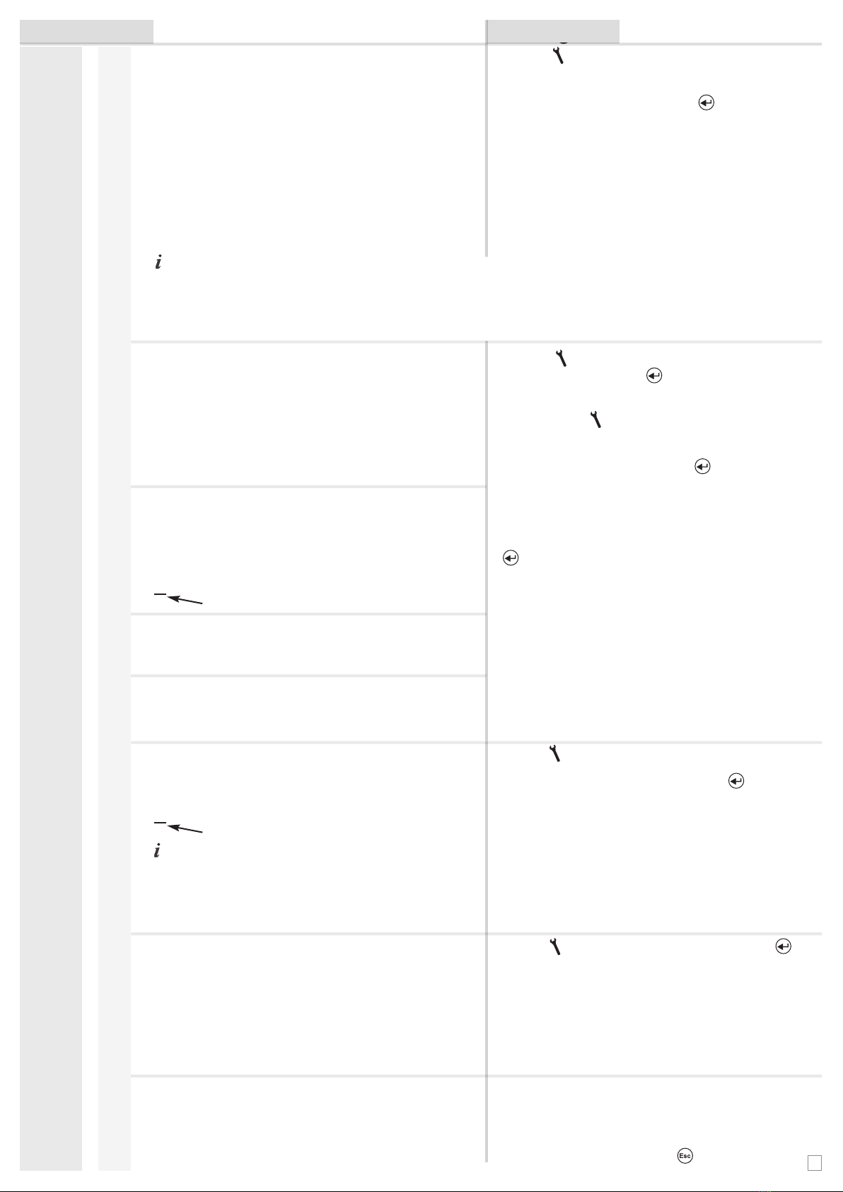
- opening the main menu
-ESC(escape)=return one step back
- browse through the main menu (view)
- browse in the “Parameters” mode
- in the “Setting program” browse between time intervals
- browse (view) information by pressing ” “
-ENTER= acknowledgement= typing changes
- quick change of the requested temp.
(short-term in the mode “Auto”,
permanent in the “Manual” mode)
- change in the adjusted value
- Press the button “LCD” to select the appearance of the introductory display of information on the display
01.01.13 21:45 Thuesday
AUTO prog:1 per.:1
IN:19.0°C DHW:50.0°C OT+
22.4°
C
Temp. DHW: 57°C OT+ Temp. DHW: 57°C OT+
actual
IN: 22.4°C
UT: 42.0°C
OUT: 8.0°C
required
IN: 19.0°C
CH: 0.0°C
DHW: 50.0°C
Actual temp. : 22.5°C
required IN : 19.0°C
required DHW : 50.0°C
outdoor: 8.0°C
- press “ “ for view following information ---------->>>>> by TURNING “ “ button next information
(about the heating system, the supply of hot service water, servicing, the outside temperature etc.)
- serves for fast copy of days in the “ Setting program” mode
- entrance/leaving into/from the service mode, press the button during about 5 s in the introductory display.
- Press the button to open the browse menu and the change the actual requested room temperature and the
automatic or manual mode
Turn the button “ “ to change the actual value of the requested temperature (in automatic mode up to the
further time section) or select another programme.
Turn the button “ “ to switch between the temperature and the programme
LCD COPY
1
2
3 4 5 6
7
Control elements Button function - PRESSING Button function - TURNING
1
2
3
4
5
6
7
01.01.13 21:45 Thuesday
AUTO prog:1 per.:1
01.01.13 21:45 Thuesday
AUTO prog:1 per.:1
Required CH= calculated central heating according
to he selected equitherm curve, according to the
weather) irrespective of min. and max, potential temper-
ature of CH, the data in brackets is the requested temp.
with respect to the adjusted min. and max. CH temper-
ature (see pages 6, 7 – constants No. 6 and 7)
Actual CH = actual temperature of heating water
Modulation = modulation output of the boiler in %
Flow= information about the flow of DHW in litres per
minute for boiler СХ and ТСХ
Required temp. DHW= required DHW temperature
Operating hours CH and DHW= reset by ”LCD”button
Temp. measured= statistics value, reset by ”LCD”button
Works boiler inspector= service telephone (see page 5)
Required temp. in AUTO/MANU mode= change by
“ “, short-term in “Auto”, permanent in “Manual” mode
Outdoor temp.= temperature on the outside temperature
sensor connected to the boiler
Required temp. in premature switching mode=
constant No. 3
- Display backlight (after pressing any button the display is automatically backlit for about 2 s.)
LCD
COPY
DESCRIPTION
UT
sign for heating on
1
On the last line is further information, for example, the outside temperature
A) B) C)

The thermostat is installed in a suitable place where it cannot be affected by the flow of hot air from the heater, solar radiation and other
heat sources. The installation height should be about 1.5 m above the ground. Install the thermostat into what is known as the reference
room (e.g. a bedroom).
The installation of PT59X must only be done by a
properly qualifi ed person!
Work procedure:
1. Remove from the device РТ59Хreal panel (Fig. No. 1).
2. Remove plastic piece in the middle of the rear cover with the size of the
hole for the supply of the communication link.
3. Fix the rear cover on the installation box or the wall (Fix No.2).
4. Put the communication link from the boiler through the created hole in
the rear panel and connect it to the terminal box according to the
diagram.
5. Connect the thermostat to the rear panel.
Note.: After connecting the leads to initialize the processor (LCD flickers), so
appropriate to start with programming at least 10 minutes after the connection.
OPERATION
Auto (set in production)
The thermostat works according to the previously set program.
Main menu
Manual
The thermostat keeps a constantly adjusted temperature.
Auto off
disconnection of the boiler up to the time for the change of
temperature stated by the program.
Manual off
Permanent disconnection of boiler.
Holiday (Auto)
Keeps a constant temperature up to the set day of return from
vacation, and is then transferred into AUTOMATIC MODE (the last
selected program before the vacation). It is not possible to set the
Summer mode (setting values, constant No. 4)!
Setting
Selection of user modes
Press the “ “ button, by turning ” “ select the Auto mode,
confirm by “ “ button. A quick change of the requested
temp. is performed by pressing the “ “ or “ “ button
(cannot be set when in the OFF mode or the
Summer mode).
Press the “ “, button, by turning” “ select the Manual mode,
confirm by “ “ button.
The quick change of the requested temperature is performed
similarly as when in automatic mode.
Press the “ “ button, by turning ” “ select the
Auto off mode, confirm by “ “ button.
(Mode “OFF in automatic “ is cancelled by selection of
another mode).
Press the “ “ button, by turning ” “ select the
Manual off mode, confirm by “ “ button.
(Mode “ OFF in manual“ is cancelled by selection of
another mode).
Press the “ “ button, by turning the ” “ select mode
Holiday (Auto), confirm by “ “ . Set the date and time of return
from vacation and the temperature which the thermostat must main-
tain during the vacation. Turn the “ “ button to change the value
and press ” “ button. After expiration of the set period of vaca-
tion, the thermostat returns to the automatic mode. The heating
of DHW is always disconnected.
(The set value always flashes, turn the “ “ to browse
between data, press ” “ button to return back to the
menu. In the case of early return from vacation, cancel the
mode “Holiday in AUTO“ so that you select another mode).
The following text is displayed:
“ Holiday to 1.1.09 15:00”
New informotion showed:
“ Requested temp. in holiday ”
the text ” Off “ is displayed
ASSEMBLY
LCD COPY
Fig No.1
Fig No.2
Instal. diagram:
PT59X
BOILER
*
OpenTherm – communication
link, length max.50 m,
without polarity
*for exact electric connection,
see the instructions for the
boiler used
2
Connection outside sensor (see page 6) (not included)
1, for measurement of temp. in other place than is thermostat placed
2, as a floor sensor
3, for DHW regulation
GST1
Transfer of data through RS232 – the
cable is part of delivery GST1, length 1.1 m
Connecting the MS2 (not included)
when error messages are normally closed
relay switches MS2, to which may be
connected to another light or acoustic
element.
MS2

Holiday (Manual)
Keep a constant temperature up to the day of return from the vacation,
then switch to the MANUAL mode (the last selected program before
departure). It is not possible to set the Summer mode (setting values,
constant No. 4!
Press the “ “ button to select Holiday (Manual), confirm
by “ “ button. Use the similar setting as in Auto mode. After
expiration of the set period of vacation, the thermostat returns to
the manual mode. DHW is always disconnected.
Main menu Setting
Programming and
setting parameters
Setting clock
setting the actual time and date.
Setting program (factory setting prog:1)
Setting programs for CH and DHW.
The thermostat can set 9 weekly programs for heaiting and 6
thermal changes per day. Programs No. 8 and 9 are designed
for automatic changes in even and odd weeks.
During selection of permanent CH temperature (4. Regulation
mode “3“ Permanent CH temperature) output temperature from
the boiler or the cascade is always set.
Press the “ “ button, by turning ” “ select the mode
Setting clock, confirm by “ “ button. Turn the “ “ to
change the values and confirm the selected values by pressing
” “ button (Symbols above the set parameter always
flash. Turn “ “ to browse between data, press the but
ton “ “ to return to menu).
Press the “ “, button and turn the” “ to select
Setting program mode, confirm by “ “. Turn the
“ “ to select the program and confirm by ” “
button. Select the requested day in the same manner.
First, select the time of the change and then the
requested room temperature. Proceed in such manner
up to the last terminal. If you know that the following day
will be the same, press the button “ COPY“. The
program is copied. The text “COPY“ flashes on the
right upper side
(the set data always flashes, turn the “ “ button
to browse between the data, press the” “ button to
go back one step back in programming).
When programming DHW, proceed in a similar manner, set
the time sections for the heating of DHW.
Program CH Program DHW*
*Control DHW: When connecting an external sensor (see diagram on page 2), No.17 constant setting to "for DHW" and
location of the sensor in the tank, there is regulation DHW according to set program (with a hysteresis of ± 5 ° C according
to location of the sensor in the tank).
Parameters
Setting the regulation parameters and the heating system.
2. Min. program. temper. (factory setting 5°C)
Temperature limit - it is not possible to set the room
temperature below this limit when programming.
Select within the range from 2 °C to 10°C (by 0.5°C).
3. Max. program. temper. (factory setting 39°C)
Temperature limit - it is not possible to set the room
temperature above this limit when programming.
Select within the range from 15 °C to 39°C (by 0.5°C).
4. Mode (factory setting 0)
Status of the mode in which the thermostat will work.
0 - Required temper.regulation, the thermo-
stat heats for requested temp. at the stated time.
1 - Premature switching (PS), during two day of opera
tion, the thermostat ascertains thermal constants
of the reference room and then switches the
heating with requested advance (for restriction of
advance, see constant No. 5 below).
2 - Summer mode, the thermostat does not heat,
only controls the heating of DHW.
3 - Permanent temp. CH, the thermostat keeps
temperature of heating water within the limits of the set
time and the constant 6 (MIN. TEMP. CH) and 7 (MAX.
TEMP. CH).
5. Start-up sooner max. (factory setting 2 hours)
When PS is activated! The thermostat may
activate the heating at the set number of hours in
advance.
Optional range 0.5 to 6.0 hours (by 0.5 hours).
Press the “ “ button, by turning the button ” “ select the
Parameters mode. Confirm by pressing the “ “.
Turn the “ “ button to browse through the constants.
Turn the “ “ button to set the minimum adjustable
temperature and confirm with ” “ button.
Constant No. 3 automatically appears.
Turn the “ “ button to set maximum adjustable
temperature and confirm with ” “ button.
Constant No. 4 automatically appears.
Turn the “ “ set the maximum time in hours to show
the time in advance it is possible to activate the heating
so that the temperature reaches the requested value by
the stated time. Confirm by ” “ button.
Constant No. 6 automatically appears.
Constants
1. Cesky (factory setting Cesky)
Selection of language.
Turn the “ “ to select and press the ” “ button.
Constant No. 2 automatically appears.
3
Select program
Program: > 1 < Monday
1. 6:00 22.0°C
2. 9:00 19.0°C
3. 14:00 22.0°C
4. 16:30 24.0°C
5. 21:30 19.0°C
6. 21:30 19.0°C
Select program
Program: > DHW < Monday
1. 0 - 24 45.0°C
2. 24 - 24 45.0°C
3. 24 - 24 45.0°C
The last program is reserved for the management of DHW. For
boilers with flow heating, it is possible to set 3 time sections with
various temperatures (from 35 °C to 60 °C ). For boilers with
tanks, the temperature of DHW is set on the boiler and on
PT59X ; setting the temperature only enables activation of the
boiler for heating the boiler.
Turn the “ “ button to select the required regulation
mode and confirm with ” “ button.
In the case of selection of the mode “ 0 ” the constant No. 5
is skipped and the constant No. 6 is immediately appeared.
In the case of selection of mode “1“ , constant No.5 auto-
matically appears (in the list of information , the text
“required temperature in premature switching“ appears).
In the case of selection of mode “2”, constant No. 5 is
skipped and constant No. 6 immediately appears (on the
introductory screen the text “Summer mode” appears).
In the case of selection of the mode “3“ the constant No. 5
is skipped and the constant No.6 is immediately appeared.
On the introductory screen the text “required IN“ and at this
mode the stated actual value of required-permanent
temperature of heating watter is appeared.

6. Min. temp. heating watter (factory setting 30°C)
States the lower limit of the requested temperature for
heating water calculated by the thermostat for when
the heating can start. This constant prevents
redundant activation of the boiler.
Optional range from 5.0 °C to 50.0°C (by 1.0°C).
7. Max. temp. heating watter (factory setting 70°C)
States the upper limit of the requested temperature of the heating
water calculated by the thermostat which the boiler must not
exceed. Difference between the minimum and ten maximum
temperature must be greater than 8°C.
Optional range from 13.0 °C to 85.0°C (by 1.0°C).
Turn the “ “ button to set the minumum temperature
of the heating water and confirm with the ” “ button.
Constant No. 7 automatically appears.
Turn the “ “ button to set the maximum temperature
of the heating water and confirm with the ” “ button.
Constant No. 8 automatically appears.
Programming and
setting parameters
Main menu Setting
4
Constants
8. Number heating curve (factory setting “Room control”)
Selection of the type of regulation.
Room control = PI regulation (according to the
inside temperature). The thermostat heats up
depending on the temperature in the reference room.
It is necessary to set constants 11 and 12!
1 - 60 = equithermal regulation, number 1 to 60
corresponds to the requested heating curve (see below)
It is recommended to select equithermal regulation for large buildings where it is not possible to select a reference room. The principle of
equithermal regulation is optimising the temperature of the water for the heating system depending on the outdoor temperature.
The mentioned equithermal curves express this dependence (for a requested room temperature of20°C), according to which it is possible to select the
requested temperature of the water in the heating system. The thermostat calculates the temperature of heating water according to the selected
equithermal curve which is consequently sent to the boiler. Then the boiler regulates the temperature of heating water to the requested value.
It is necessary to select the slope of the curve according to the heating system to prevent permanent over or under heating of the building.
The selection of the correct curve for the stated system is a long-term issue and it is necessary to test the system at various outdoor temperatures! It is
recommended to modify the indoor temperature in the rooms, e.g. regulation by thermostat heads. The water temperature in the heating system is
restricted by minimum and maximum limits which are set in constants No. 6 and 7! During this regulation, the outdoor sensor must always be
connected to the boiler!
Turn the “ “ button to select the type of regulation
and press the ” “ button to confirmation.
In the case of selection of equithermal regulation follow
the instructions under the graph with the heating
curves.
If selecting a requested room temperature of other than
20 °C, the thermostat calculates the automatic shift of the
curve according to the following equation where the
coefficient is 1:
shift = (requested temper. - 20) * coefficient
Note.: the most frequently used curve under our conditions
is 9-11 for low-temperature systems and 15-17 for traditional
heating systems.
After selection of the optimal heating curve and the
confirmation, there is a shift to constant No. 9.
In the case of option PI regulation constants No. 9, 10 are
skipped and constant No.11 is automatically displayed for
further setting of the Pl regulation.
9. Parallel displac. h.c.
0.5 to 10.0 =manual correction according to the
coefficient, used if the temperature is not
according to your requirements (by 0.5).
In the case of this regulation, the heating curve is automatically corrected depending on the outdoor temperature, as well as
the actual temperature in the reference room where the thermostat is located. This enables to achieve higher thermal comfort in
the heated area, optimal operation of the heating system and greater savings! During this regulation, the sensor must always be
connected to the boiler and constant No. 9 must be set to „AUTO”!
AUTO= automatic correction, according to the
indoor temperature measured in the reference
room. It is possible to use this option after the
correctly selected equithermal curve!
Example describes the option for equithermal curve No. 13
(pink) and the calculated correction with the coefficient 2.5
(for requested room temperatures of 24 °C and 16 °C). The
optimal setting of the system is achieved when the water tem-
perature of the heating system is regulated according to the
actual outdoor temperature.
In the case of setting the equithermal regulation, it is possible
to select manual correction of the shift of the curve or the
automatic correction according to the indoor temperature.
Turn the “ “ button to set the correction for the curve and
press the ” “ button to confirm.
In the case of manual correction set the shift coefficient
for the heating curve when at various requested tempera-
tures in the reference room, regulation of the heating water
will be reached according to the actual outdoor tempera-
ture (for the formula, see constant No. 8).
After setting and confirmation, there is the automatic
transfer to constant No. 10.
In the case of option automatic correction according
to the indoor temperature, constants No. 10, 11 and
13 must be set.
Omezení max. teploty
vody top. sys. (Konst. 7)
Omezení min. teploty
vody top. sys. (Konst. 6)
external sensor
temperature [°C]
required temperature of
heating system [°C]
external sensor
temperature [°C]
required temperature of
heating system [°C]
designation of curves

13. Reaction speed (factory setting 12)
Active only in the case of selection of equithermal regulation
with automatic correction according to the indoor
temperature! States how fast the requested temperatures
are achieved. Optional range 1 to 16 (by 1).
Turn the “ “ button to select the value and press ” “
button to confirm. Constant No. 14 automatically appears.
At the speed of reaction 1 the requested temperature is achieved
slightly, which prevents possibility of overusing, although the
requested temperature is achieved later. At the speed of reaction
16, in the case of the change of the requested temperature, there
is immediate heating up to the requested temperatures, but
overusing occurs.
Setting
Constants
Programming and
setting parameters
Main menu
5
11. Reg. period in minutes (factory setting 10 min.)
It is selected according to the thermal inertia of the
object. The optimal setting is 10 to 15 min.
Optional range 5 min to 20 min (by 1min).
12. Reg. period in °C (factory setting 2°C)
Only in the case of the option PI regulation (constant 8
= without equitherm). The “zone of proportionality“ from
when the thermostat starts to restrict the CH temp.
(when the PI regulation starts). Optional range
1.5°C to 3.0°C (by 0.1°C).
The principle of PI regulation is based on comparing the
actual temperature of the room with the requested tem-
perature. This regulation depends solely on the indoor
thermostat sensor. Selection of constants 11,12: when
setting the time section, it is necessary to ensure the thermal
inertia of the room. The optimal setting is 10-15 minutes.
If there are frequent thermal deviations in the room it is rec-
ommended to select a shorter time section. Zone of propor-
tionality states from which value the PI regulations will start.
14. Day of service (factory setting 1.1.2029)
Setting the date for servicing the boiler. Notification for the
user regarding the maintenance of the boiler.
Turn the “ “ to set regulation interval and press ” “
button. Constant No. 12 or No. 13 automatically appears (at
the equitherm with automatic balancing).
The length of the interval in minutes influences the oscilla-
tion of the system. The lower this value, then the higher the
risk of oscillations.
If selecting the PI regulation (constant No. 8), it is necessary
to set the further parameter.
Turn the “ “ zone of the proportionality of PI regulation
and press the ” “ button. There is the automatic
appearance of constant No. 14.
In the case of selecting the PI regulation parameters,
orientate according to the PI regulation and follow
instructions shown at the graph.
Turn the “ “ button to consequently set day, month and
year for the revision and confirm each setting by the ” “ .
To speed-up the setting, press the button “COPY“, which
displays the actual date. The revision is cancelled by the change
of the date of revision. After setting constant No. 17 automati-
cally appears (or 15 in service mode).
At the stated date, the text “ revision of the boiler
is required” is shown on the display.
15. Name of technical expert
Display of the name of the service technician. The name of
your service technician appears on the display. Active only
when in service mode.
16. Phone of technical expert
Display of the telephone number of the service technician.
The name of your service technician appears on the display.
Active only when in service mode!
Constants 15 and 16 can be set in service mode!
Opening service mode: twice press the ” “ button re-
turn to the introductory menu in the same manner and then
press the button „COPY“ for 5 s. Entrance into the service
mode is indicated by the text “SR“ in the right lower corner
of the display.
Press the “ “ button, select the “Parameters“ mode,
confirm by pressing the “ “. Turn the “ “ button select
the constant No. 15. Turn the “ “ button and set the tech-
nician name, each letter confirm by ” “.
Proceed in the same manner as when setting the telephone
number.
Termination of service mode (output from SR):
In the introductory menu, press the button „COPY“ for 5 s.
Do not make any changes and you are in the introductory dis-
play, there is automatic termination of the service mode within
4 minutes.
10. Building insulation
The speed of the change of temperature in the room during
frequent deviations of outdoor temperature depends on the
construction and insulation of the building. With this constant, it
is possible to take into consideration the speed of the change of
temperature according to the type of heated building (only in the
case of equithermal regulation.
badly = uninsulated building, responds quickly to a change in
the outdoor temperature
medium = insulated building, responds slowly to a change in
the outdoor temperature
well = well insulated building, responds slower to the
changes in the outdoor temperature
Turn the “ “ button to select the type of the building
according to the kind of insulation and press the ” “
button. There is the automatic appearance of constant
No. 14 (during manual correction) or No. 11 (during
automatic correction).
If stated, a new item appears in the information, for
examples SERVICE TECHNICIAN).
If stated, a new item appears in the information.
Example: Service technician
VASILEV
89876543210
Preset temperature
Proportional
band
Heating on at
100 % of the
working cycle
25. Version (reset of the factory setting)
Only for information regarding the firmware version of
the thermostat. Option to reset the factory setting
- reset.
Setting
Constants
Programming and
setting parameters
Main menu
6
17. Temper. 2nd sensor (factory setting “not used”)
Option to use the external room sensor (not the outdoor
temperature sensor).
Disconnect = external sensor is not connected, if connected,
it functions as an indoor sensor and regulation is according to
the temperature measured on the connected sensor.
For DHW = external sensor is placed in water tank and
regulate DHW (temper.program select for DHW see
page3).
15.0°C to 80.0°C = external sensor is used to restrict the
maximum temperature (e.g. heated floor, etc).
18. Use GSM (factory setting NO)
Option to use GST1 module for remote control of the
thermostat by mobile telephone.
NO = modul GST1 module is not connected
YES = modul GST1 is connected, the following
constants No. 20 and 21 must be set and the module
must be connected according to the respective manual!
19. Phone No. 1
Entering the telephone number in an international
format (79876543210), to which SMS are sent
back regarding the status of the thermostat.
79876543210
22. Pin
Setting the PIN code for the SIM card which is
inserted into the GST1 module.
* * * *
The version number of the firmware appears with the text
“COPY“. With the second pressing of the button „COPY“ (for
about 5 s) there is RESET OF THE FACTORY SETTING (on
the display above this button the text is displayed “reset“). To
return to the main menu use the “ “ button.
If the sensor is connected, the text will appear at the constant “ Sensor connected”. In the introductory LCD the value of
the temperature of the external sensor appears “ External sensor: XX.X°C.
If the sensor is not connected (or the sensor was disconnected) and constant No. 17 is set for the use of this sensor, the
notification “ External sensor error” appears. In information, a new item appears according to the use of the external sensor:
“ Regulation according to the 2nd sensor“/“ Temp.DHW sensor “/ “ Temp. 2nd sensor “.
Turn the “ “ in upward direction and set maximum temper-
ature measured by the external sensor (within the range 15 °C
to 80 °C), at which there is the disconnection of the boiler.
Setting is confirmed by pressing the “ “.
If the temperature measured by the external sensor reaches
the set value, there is the disconnection of UT and
on the display, the text “Disconnected-external sensor
appears“.
After setting, constant No. 18 appears.
Turn the “ “ button to set the option for using the module
GST1and press the button “ ” to confirm. There is the
automatic appearance constant No. 19 (if the module is not
used, constants 19, 20, 21, 22 is automatically skipped).
Turn the button “ “ to gradually set the numbers which
correspond to the telephone number for sending SMS
messages sent from the thermostat. Each number entered
ust be acknowledged by the button “ “. After setting the
last number, constant No.20 automatically appears
1st numeral
The telephone number is entered in the international format
(without “+“ or “00“ at the beginning). In the case that the
telephone number has 10 or 11 digits, an empty place is set on
the last position after entering the last number. Press the button
“ “ to switch to the next constant. In the case that you do not
want to enter the next telephone number, constant No. 20
“Phone No. 2” and No.21 “Phone No. 3” are left empty. When
setting constants No. 20, 21 the procedure is the same!
1st numeral
Individual characters of the PIN are not visible due to the
high level of security against misuse of the SIM card.
Turn the “ “ button to gradually enter the PIN code for the
card, to be inserted into the GST1 module. Each time the
number is entered it must be confirmed by “ “. After enter-
ing the last number PIN code, connect the conductor into the
GST1 module and connect the module into the socket. As
soon as the orange diode lights up, press the button “COPY”
(on the display above this button the following text is displayed
“1st attempt of 3”). Then, there is the testing of the correct
connection of module GST1 and verification of the PIN code.
If the PIN is incorrectly entered, the following text appears “In-
correct PIN“ and “2nd attempt of 3”. In the case of further
incorrect entering of the PIN, the following text appears “ Last
attempt”.
.
23. Legionella function (factory setting NO)
Ensures the control of the TUV tank for the minimum
temperature of 60°C, which kills all potential Legionella
bacteria.
NO = the function is not active
YES = the function is active, the value in the bracket is the
number of days, which remain to the automatic heating (always
by 5 days, if the temperature of the TUV does not exceed 60°C)
Turn the “ “ button to set the option and press the ” “
button to confirm. Constant No. 25 automatically appears.
Conditions for the correct function:
There must be information about the temperature of the DHW
from the boiler or the 2nd sensor must be in the function for
„HSW“!
The automatic heating always takes place at midnight.
20. Phone No. 2
Entering the telephone number in the international
format (79988776543) - not obligatory.
21. Phone No. 3
Entering the telephone number in the international
format (79988776543) - not obligatory.
When setting telephone numbers 2 and 3, the function is as follows:
1, SMS “ Info” will be sent from tel. numbers 2nd or 3rd, answer will be
sent to tel. number 2nd or 3rd;
2, SMS “Temp xx” will be sent from tel. numbers 2nd or 3rd, answer will
be sent to tel. number 1st;
3, If an error status is reported, an SMS is sent to tel. no. 1, 2 and 3;
4, If an SMS is sent from other tel. number, the reply is always sent only
to tel. number 1st.
5, SMS “Call” will be sent, the call is only on tel. number 1
!If the PIN is incorrectly entered three times, disconnect the module
and restart the thermostat. Remove the SIM card and insert it into the
telephone and activate the SIM card by entering the PIN. Then enter
the PIN again!

7
REMOTE CONTROL BY MOBILE TELEPHONE
FORMAT OF SENT MESSAGES
Info
Off
Temp xx
Call
information on the status of the heating system
disconnection of the heating system (in the AUTO mode - short-term, in the MANU mode - per-
manent), use to cancel the function to use the message Temp xx
change in the requested temperature (only integers can be entered and these must be within
the range of permitted minimum and maximum temperatures – constants No. 2 and 3)
back calling
xx = value of temperature in °C (always a 2-digit number, e.g. 15)
Attention: To send and receive back messages, any type of mobile telephone can be used! If the telephone
has the option to set the size (format) of the font, always use MEDIUM size (option for three font sizes) or
LARGE size (option for two font sizes).
!
Require: xx.x
Act: xx.x
On
Sig: x
Requested temperature (entered by the user)
Actual room temperature
Activated heating system (On)
states the value of the signal in the place of the location of the module where x
are values within the range 0 to 5:
0..cannot be determined or no signal is detected
1..the worst signal level
5..the best signal level
FORMAT FOR BACK MESSAGES FROM PТ59X
Off Deactivated heating system (Off)
AUTO The thermostat is in automatic mode
MANU The thermostat is in manual mode
Noakcept! Signals an error (incorrectly entered SMS, etc.)
xx.x = temperature in °C
Note: In the case of exceeding the min./max. temperature in the room (set constants 2 and 3) a
"WARNING " SMS is automatically sent in the Info form.
Specify the conditions for sending messages with your operator. We recommend using the services of
the mobile operator with the best connection.
BACK MESSAGES ARE SENT WITHIN 3 MINUTES!
DÁLKOVÉ OVLÁDÁNÍ MOBILNÍM TELEFONEM
pomocí modulu GST1
HOLI the thermostat is in vacation mode, keeps the constant temperature up to the stated date
Sens 2: xx.x Absolute temperature of the external sensor, if connected (see pages 2,6)
Out: xx.x Actual temperature of the outdoor sensor which is connected to the boiler
CH Indicates that heating is to CH
DHW Indicates that the heating is to DHW
E xxx Error message where xxx is the indication of error 001 to 255 (see page 8)

Power supply Through the OT communication link from the boiler
Communication link double link
polarita without polarity
length up to 50 m
Type of communication Bi-directional OpenTherm
Hysteresis DHW ±5°C
Range of adjustable temperatures 3 to 39°C
Range of adjustable CH temp. 5 to 85°C
Range of adjustable DHW temp. 35 to 65°C
Precision of measurement ±0,5°C
Protection IP20
Relative humidity < 85% RH
Working temperature 0°C to +40°C
TECHNICAL PARAMETERS
CERTIFICATE OF GUARANTEE
(guarantee period for the product amounts to 2 years)
product No.: date of sale:
stamp of shop:
examined by:
In case of guarantee or post-guarantee
service, send the thermostat to
the manufacturer’s address.
v souladu s RoHS
LEAD FREE
ERROR MESSAGES
Warranty rules: If a defect occurs in the product during the warranty period caused by a manufacturing defect or
a defect to the material, it will be removed free of charge. To apply the warranty, the purchaser must submit a
valid warranty certificate.
The warranty period is stated:
a. on the package of the product
b. in the manual for the product
The warranty does not apply to defects caused by:
1. unprofessional use (in variance with the User
Manual)
2. poor handling
3. penetration of other substances into the product
4. natural disasters
5. mechanical damage caused by the user
6. non-functioning of equipment caused by error
installation
The warranty certificate must contain
1. stamp, signature and address of the seller
2. day, month and year of the sale
3. exact indication of the product (model) and
the serial number of the boiler to which the prod-
uct applies
The warranty looses validity
1. if the warranty certificate is not correctly or
only partially completed
2. in the vase of self made changes to the war-
ranty certificate
3. in the case of not keeping to the intended
manner of use and maintenance of the product
4. intervention by unauthorized persons into the
product
5. unprofessional repair of the product
The OpenTherm protocol enables to send important error messages from the boiler into the thermostat.
The thermostat displays these messages on the last line of the display:
-E xxx , where xxx can be from 001 to 255. This type of error can be changed according to the model of the boiler (see
technical sheet) or according to the form of the connection of thermostat PT59X to the driving boiler in the cascade; therefore,
a service technician may need to be called. These are errors, e.g. bad exhausting of burnt gases, error in the outdoor
temperature sensor, etc. In the case of a cascade connection, there may be an interruption to the connection between individual
boilers in the cascade.
- Error in measurement of UT temperature = the inside sensor is damaged, contact a service technician.
- Error OPT - UT temperature = no information received from the boiler for the actual UT temperature.
Note: error xxx is displayed, the first line of the display starts to flash (date and time) to highlight the error status!
In the case of disconnection or interruption of a communication link between the thermostat and the boiler, the text ”Connect
the link”is displayed (during the first connection, the thermostat must be connected with the boiler through the link for about
30 minutes).
The advantage of this thermostat is an extremely long period for running the backup of the data and time module
(i.e. it is not necessary to set them again) – for more than 10 days from the date of disconnection from the source!
If the breakdown of the communication link is extremely long, it is necessary to set the date and the time, although the con-
stants and programs remain kept in the thermostat!
In this case, on the last line of the display, there is the notification „Set the date and the time“.
www.thermona.cz
Pb
f.w. - PT59X - V11.11Т
This manual suits for next models
1
Table of contents
Popular Thermostat manuals by other brands

Gemtech
Gemtech GT5020 Operation manual

Honeywell
Honeywell RTH7400 series installation guide

Robertshaw
Robertshaw 9801i2 Specifications

Venstar
Venstar T1070 Owner's manual and installation instructions

White Rodgers
White Rodgers 1F87-0261 Installation and operating instructions

PSG
PSG NPK-4120U-1 Installation and operating instructions


